PERFORMANCE ANALYSIS OF
TMS320C6713 AND 6745 DSPs USING
TFBBGAR FFT ALGORITHM
R. Priyakanth1 Mahesh Babu Katta2Assistant Professor, Department of Electronics & Communication Engineering, BVRIT Hyderabad College of Engineering for Women, Hyderabad, Telangana, India
[email protected], [email protected]
Tejaswini Kunam3, Chidipothu Venkata Kalyani4, Daggula Bhavitha5, Gadhiraju Sravani6 Department of Electronics & Communication Engineering,
BVRIT Hyderabad College of Engineering for Women, Hyderabad, Telangana, India [email protected], [email protected], [email protected],
[email protected] Abstract
Digital Signal Processors bring real-time signal processing, computing performance, and power efficiency to assorted applications ranging from wide variety of sensors to complex servers. Due to wide range of applications in different research areas many manufacturers are developing more dominant DSP processors challenging greater computational performance. As systems become more complex and processor preferences grew up, good estimates of processor’s performance can be done by measuring CPU clock cycles and application execution time required, permitting a designer to judge the relative suitability of each processor for the application. This work is to evaluate the performance of Texas Instruments make TMS320C6713 and TMS320C6745 DSP processors using conventional FFT and Twiddle Factor Based Butterfly Grouping and Reduction Method of FFT by comparing CPU clock cycles required and application execution times for a specific input. This work evaluates the performance of the specified DSP processors and the performance of multiple FFT approaches.
Keywords: FFT; TMS320C67xx; CPU clock cycles; Execution time. 1. Introduction
In the last three decades, more attention has been paid towards processing signals in their digital format. Several customized hardware products for digital signal processing are now available in the market. They are becoming more efficient, consistent, flexible, and user friendly [13]. Based on the availability of numerous DSP algorithms, the Market of DSP processors has been growing rapidly. A variety of new DSP processors based on different architectures have been introduced to the market in the last two decades to meet the need for a wide range of applications. As a result, performance measurement of DSP processors became a significant issue for both the manufacturers and the users. Feedback is more important for the DSP manufactures to improve their design and customers must compare a variety of DSP processors and select the appropriate one that meets their necessities in a cost-efficient way [14].
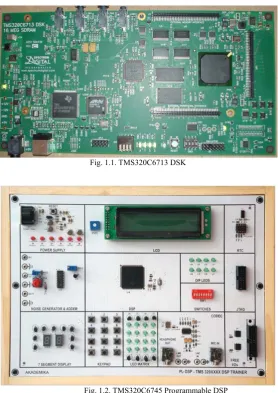
The TMS320C6713 DSP Starter Kit (DSK) is an economical standalone development platform that enables users to evaluate and build up applications for the TI C67xx DSP family. The DSK also serves as a hardware reference design for the TMS320C6713 DSP [15]. Its high-performance CPU and rich peripheral set are developed for multichannel audio applications. Some of them include broadcast and recording mixing, home and large venue audio decoders, and multi-zone audio distribution [16].
The TMS320C6745 device is a new generation [8], low-power digital signal processor based on a TMS320C674x DSP core. It consumes appreciably lower power than other members of the TMS320C6000 platform of DSPs. The TMS320C6745 device supports Original-Equipment Manufacturers (OEMs) and Original-Design Manufacturers (ODMs) to swiftly bring devices featuring high processing performance into the market [17]. These DSKs are designed to work with TI’s Code Composer Studio development environment. Code Composer studio communicates with the board through the on-board JTAG emulator [15]. TMS320C6713 DSK and TMS320C6745 Programmable DSP used for performance evaluation are shown in Figure 1.1 and 1.2. The C/C++ compiler available with IDE tool translates the source program into machine language object code that the TMS320C6000 can execute. Source code must be compiled, assembled, and linked to create an executable object file [10]. The TI C64x DSPLIB is an optimized DSP Function Library for C programmers using TMS320C64x devices. This includes commonly used DSP routines [11].
output. When the DFT is implemented as an efficient algorithm called Fast Fourier Transform (FFT). The most popular FFT algorithms are the radix 2 and radix 4, in either decimation in time or decimation in frequency signal flow graph form [2]. The importance for FFT has been derived from its increased applications in wide range of research fields like Astronomy, Medicine, Speech Processing, Signal and Image processing, etc.
Fig. 1.1. TMS320C6713 DSK
Fig. 1.2. TMS320C6745 Programmable DSP
Experiments based on FFT are conducted on the above mentioned popular DSP processors. Besides their popularity, the reason we select these DSP processors is because of their support for highly accurate applications. By compiling and running the FFT algorithms which are a subset of C benchmark programs [14] [18], we perform both dynamic and static measurements and the performance metrics are recorded to analyse the experimental results and evaluate the performance of the DSP processors. The results obtained for different inputs are verified using MATLAB [6] for further real-time implementation on DSP hardware.
2. FFT Algorithms
The importance for FFT has been derived from its increased applications in wide range of research fields like Astronomy, Medicine, Speech Processing, Signal and Image processing, etc. For viewing the spectral content of a real-time signal or sequence, the standard system analysis tool is the Fourier transform. The Fourier transform of a sequence, i.e Discrete Time Fourier transform (DTFT) is not suitable for real-time implementation [1]. Taking a sequence as input, DTFT outputs a continuous function of frequency. A nearby comparative to the DTFT is the Discrete Fourier Transform (DFT). The DFT gives finite length sequence as output taking a finite length sequence as input. Implementing DFT in an efficient algorithm is called the Fast Fourier Transform (FFT). FFT makes itself suitable to real-time implementation. Radix-2 and Radix-4 are the most prevalent FFT algorithms, in either Decimation in Time (DIT) or Decimation in Frequency (DIF) signal flow graph arrangement. FFT achieves to decrease the complexity of computing the DFT from O(N2), which ascends if one
2.1. ConventionalRadix-2 DIT and DIFFFT
The DFT of a discrete sequence x(n) is directly computed using equation (1) with twiddle factor defined in equation (2).
, 0,1,2, … . 1 1
2
Decomposition of DFT computation into successively smaller DFT computations is required to attain the dramatic rise in efficiency to which we have mentioned. Both the symmetry and periodicity of the complex exponential are exploited in this process. Decimation-in-Time algorithms [3] involve decomposition of the input sequence x(n), into successively smaller sub-sequences with even and odd indices, whereas Decimation-in Frequency algorithms involve decomposition of X(k).
The basic single butterfly computation in any stage of DITFFT is shown in Figure 2.1 based on which the complete butterfly structure for Radix-2 DITFFT for N=8 is shown in Figure 2.2.
Fig. 2.1. Basic butterfly computation in DITFFT [9]
Fig. 2.2. Radix-2 Butterfly structure – DITFFT (N=8)
The butterflies are calculated according to the index order of the stages and groups by subdividing the radix-2 DIT and DIF FFT structures. From top to bottom, the butterflies are computed within the same group. The basic single butterfly computation based on which X(k) is calculated using DIFFFT is shown in Figure 2.3. The Radix-2 DIFFFT structure can be said as a transpose of DITFFT and is shown in Figure 2.4.
Fig. 2.4. Radix-2 Butterfly structure – DIFFFT (N=8)
2.2. Twiddle Factor Based Butterfly Grouping Method (TFBBGM)
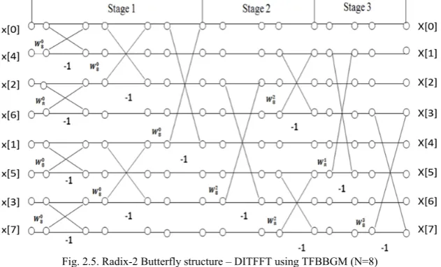
The TFBBGM [1] groups the butterflies in radix-2 FFT structure according to the twiddle factor. Thus, the number of redundant memory references due to twiddle factor in conventional radix-2 DITFFT algorithm can be minized when each twiddle factor is loaded once in the computation order. The modified butterfly structure for radix-2 DITFFT using TFBBGM is shown in Figure 2.5.
Fig. 2.5. Radix-2 Butterfly structure – DITFFT using TFBBGM (N=8)
By using the new stages as depicted in Figure 2.5, the TFBBGM method loads each twiddle factor only once in the computation. From the new structure, it is true that totally N-1 butterflies with twiddle factor = 1 will be computed without multiplication which in turn helps to reduce the number of clock.
2.3. Twiddle Factor Based Butterfly Grouping and Reduction Method (TFBBGAR)
Combining the grouping mentioned in the section 2.2 with the process of reducing the number of twiddle factors, TFBBGAR method is evolved. This method reduces the number of twiddle factors to be referenced by implementing the complex properties of the twiddle factor [12].
For example, in the butterfly structure, can be replaced by by using the conjugate property of the complex number, the derivation procedure is shown in equation 3.
. . 3
The similar concept can be applied to . Hence, only and are needed in the computation of 8 points radix-2 DIT and DIF FFT.
; ,
/ . / . / ; ,
/
. / / ; ,
/
. / . / ; ,
(4)
3. FFT Implementation using TFBBGAR method
The number of CPU clock cycles are minimized by implementing TFBBGAR method [12], as this algorithm reduces the number of memory references [5] due to twiddle factors. However, in some cases number of clock cycles are increased as they increase the code complexity to some extent. These methods are executed with iterative and recursive coding.
The memory references due to twiddle factor are reduced by half in each stage of computation by implementing
the TFBBGAR algorithm. The number of memory references due to twiddle factors is reduced to (log2N-2) × N/4 as the butterflies in last two stages are computed without twiddle factors. The number of
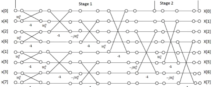
memory references due to twiddle factor in TFBBGM [1] are reduced by grouping the butterflies with identical twiddle factor and complete multiplication is not needed for the butterflies with twiddle factor , so N/2-1 is the number of memory references due to twiddle factor. The number of memory references due to twiddle factor in the new radix-2 N-points DIFFFT code will be reduced to N/4-1 after applying butterfly grouping and reduction methods together. Figure 3.1 shows the computation diagram of an 8-point radix-2 DIF-FFT with TFBBGAR method. Since the butterflies computed in the last step do not need twiddle factor since = 1, only one twiddle factor is required.
Fig. 3.1. Radix-2 DIFFFT structure with TFBBGAR Method for N=8
Butterfly grouping and reduction method is also applied to radix-2 DITFFT. The number of memory references due to twiddle factor will be greatly reduced same as that of radix-2 DIFFFT. However, because to the difference of DIF and DIT FFT, the input of radix-2 DIT FFT should be in bit-reversed order before TFBBGAR method is applied to radix-2 DITFFT. Figure 3.2 shows the computation diagram of an 8-point radix-2 DITFFT with TFBBGAR method[12]. From the modified butterfly structure, it is seen that only 4 twiddle factors are used during computation. Since = 1, twiddle factor will not be loaded in Stage 1. Hence, during the computation only one twiddle factor is loaded.
4. USB Communication with Target DSP
The Communication between the target DSP and the IDE tool used for programming is done using USB.
4.1 JTAG Emulator
The C6000 family of high-performance DSPs is targeted at high-end data concentrated applications. Such applications tend to have large code sizes and require high bandwidth on JTAG communications. For this reason, the most important feature for an emulator for these devices tends to be speed.
Fig. 4.1. XDS100V2 JTAG Emulator
The JTAG emulator shown in Figure 4.1 is USB Bus powered. It supports USB 2.0 (480mbps) and is compatible with +1.8V or +3.3V JTAG interfaces. It also supports targets with 14-pin JTAG header. It provides users with entry level JTAG debug capabilities for specific TI processors.
4.2 Code Composer Studio V 5.0
Code Composer Studio (CCS) is the DSP industry's first fully Integrated Development Environment (IDE) with DSP-specific functionality. With this IDE one can edit, build, debug, profile and manage projects from a single combined environment. Additional unique features comprise graphical signal analysis, injection/extraction of data signals via file I/O, multi-processor debugging, automated testing and customization via a C-interpretive scripting language and much more. CCS v 5.0 has a complete scripting environment allowing for the automation of repetitive tasks such as testing and performance benchmarking. The scripting console in this version of CCS allows the user to type commands or to execute scripts within the IDE.
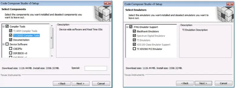
The CCS communicates with the DSK via a USB connection to a PC. The support for different families of DSP and Emulator is obtained for CCS during its installation as shown in the Figure 4.2 In addition to facilitating all programming aspects of the C67xx DSP, the CCS can also read signals stored on the DSP’s memory, or the SDRAM, and plot them in the time or frequency domains.
Fig. 4.2. Code Composer Studio v 5 setup window selecting compiler tools and JTAG Emulator support
5. Profile Clock Setup in Code Composer Studio
Certain instructions require additional CPU cycles to complete the execution. The implementation of this algorithm can be compared with the conventional FFT using CPU cycle count which is required for the execution of the program.
Fig. 5.1. CPU clock cycle count indicated in taskbar of CCS
The profile clock displays the direct CPU cycle count. Therefore its value must be multiplied by 1/CLK to convert it to seconds. TMS320C6713 DSK target runs at 225 MHz and TMS320C6745 at 375MHz. For example, if the target is running at 375MHz and the Profile clock cycle count for a routine is 217,759 as shown in Figure 5.1, then the execution time [7] by the routine would be: 217759 * (1/375,000,000) = 0.5806906 milliseconds
The clock setup can be done only in runtime and it can be reset manually or automatically. This selection is done as exposed in Figure 5.2.
Fig. 5.2. CPU clock cycle count reset option in CCS
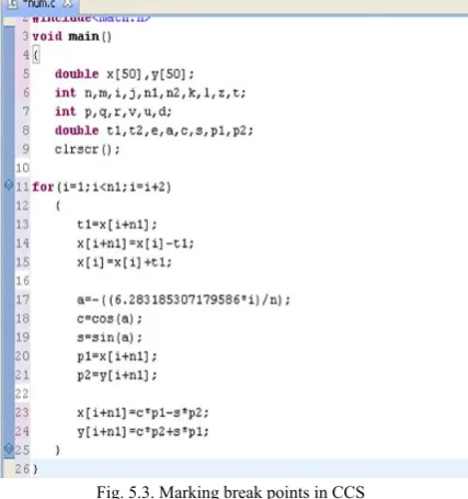
The CPU clock cycle count can be measured using Profile clock and can be measured between any two instructions within the code by setting the breakpoints on left pane of the editor in the form of blue dots as indicated in Figure 5.3.
Fig. 5.3. Marking break points in CCS
6. Results and Performance Evaluation of DSPs
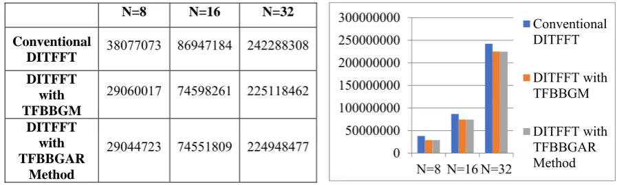
Fig. 6.1. Comparison of CPU Clock cycle count (y-axis) for sequence length N=8,16,32 on TMS320C6713 in CCS
Fig. 6.2. Comparison of Time Elapsed in seconds (y-axis) for sequence length N=8,16,32 on TMS320C6713 in CCS
It has been observed from the Figure 6.1 and 6.2 that TFBBGAR method on TMS320C6713 requires less number of CPU clock cycles and hence execution time when compared to conventional DITFFT and TFBBGM methods. The same is the case with TMS320C6745 as shown in Figure 6.3 and 6.4 for the experimental lengths taken as N=8, 16, 32.
Fig. 6.3. Comparison of CPU Clock cycle count (y-axis) for sequence length N=8,16,32 on TMS320C6745 in CCS
Fig. 6.4. Comparison of Time Elapsed in seconds (y-axis) for sequence length N=8,16,32 on TMS320C6745 in CCS
0 50000000 100000000 150000000 200000000 250000000 300000000
N=8 N=16 N=32
Conventional DITFFT DITFFT with TFBBGM DITFFT with TFBBGAR Method 0 0.2 0.4 0.6 0.8 1 1.2
N=8 N=16 N=32
Conventional DITFFT DITFFT with TFBBGM DITFFT with TFBBGAR Method 0 500,000 1,000,000 1,500,000 2,000,000 N=8 N=16N=32 Conventional DITFFT DITFFT with TFBBGM DITFFT with TFBBGAR Method 0 0.001 0.002 0.003 0.004 0.005 0.006
N=8 N=16 N=32
Conventional DITFFT DITFFT with TFBBGM DITFFT with TFBBGAR Method
N=8 N=16 N=32
Conventional
DITFFT 38077073 86947184 242288308
DITFFT with TFBBGM
29060017 74598261 225118462
DITFFT with TFBBGAR
Method
29044723 74551809 224948477
N=8 N=16 N=32
Conventional
DITFFT 0.1692314 0.3864319 1.0768369 DITFFT
with TFBBGM
0.1291556 0.3315478 1.0005264
DITFFT with TFBBGAR
Method
0.1290876 0.3313413 0.9997710
N=8 N=16 N=32
Conventional
DITFFT 5,73,463 9,97,108 18,67,083 DITFFT
with TFBBGM
5,49,335 9,90,241 13,57,013
DITFFT with TFBBGAR
Method
5,48,670 9,88,749 13,00,133
N=8 N=16 N=32
Conventional
DITFFT 0.001529 0.002658 0.004978 DITFFT
with TFBBGM
0.001464 0.00264 0.003618
DITFFT with TFBBGAR
Method
It is obvious that as the length of sequence increases, number of CPU clock cycles increase in turn increasing the time elapsed. This has been observed as true for TMS320C6713 as well as TMS320C6745. The performance evaluation parameters drastically decrease in the case of TMS302C6745 compared to 6713 DSK.
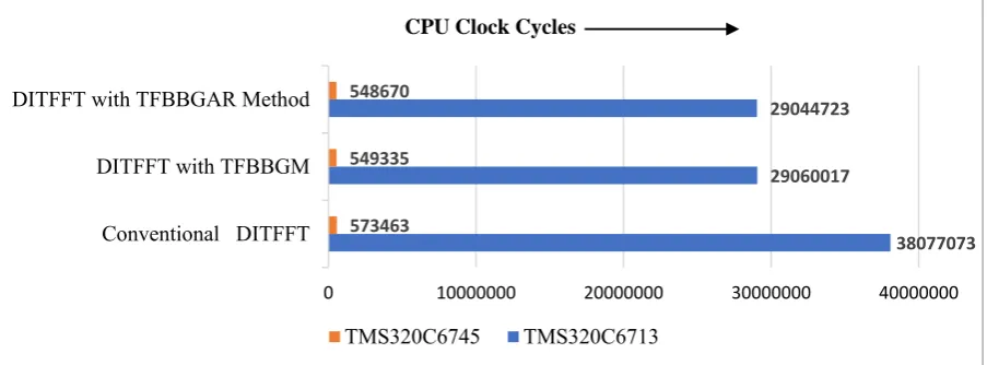
Fig. 6.5. Comparison of CPU Clock cycle count (x-axis) for sequence length N=8 in CCS
Fig. 6.6. Comparison of CPU Clock cycle count (x-axis) for sequence length N=16 in CCS
Fig. 6.7. Comparison of CPU Clock cycle count (x-axis) for sequence length N=32 in CCS
38077073 29060017
29044723
573463 549335 548670
0 10000000 20000000 30000000 40000000
Conventional DITFFT DITFFT with TFBBGM DITFFT with TFBBGAR Method
CPU Clock Cycles
TMS320C6745 TMS320C6713
86947184 74598261 74551809
997108 990241 988749
0 20000000 40000000 60000000 80000000 100000000
Conventional DITFFT DITFFT with TFBBGM DITFFT with TFBBGAR Method
CPU Clock Cycles
TMS320C6745 TMS320C6713
242288308 225118462 224948477
1867083 1357013 1300133
0 50000000 100000000 150000000 200000000 250000000 300000000 Conventional DITFFT
DITFFT with TFBBGM DITFFT with TFBBGAR Method
CPU Clock Cycles
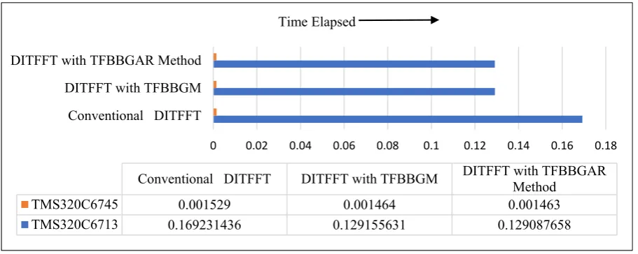
Fig. 6.8. Comparison of Time Elapsed (x-axis) for sequence length N=8 in CCS
Fig. 6.9. Comparison of Time Elapsed (x-axis) for sequence length N=16 in CCS
Fig. 6.10. Comparison of Time Elapsed (x-axis) for sequence length N=32 in CCS
0 0.02 0.04 0.06 0.08 0.1 0.12 0.14 0.16 0.18
Conventional DITFFT DITFFT with TFBBGM DITFFT with TFBBGAR Method
Conventional DITFFT DITFFT with TFBBGM DITFFT with TFBBGARMethod
TMS320C6745 0.001529 0.001464 0.001463
TMS320C6713 0.169231436 0.129155631 0.129087658
Time Elapsed
0 0.05 0.1 0.15 0.2 0.25 0.3 0.35 0.4 0.45
Conventional DITFFT DITFFT with TFBBGM DITFFT with TFBBGAR Method
Conventional DITFFT DITFFT with TFBBGM DITFFT with TFBBGARMethod
TMS320C6745 0.002658 0.00264 0.002636
TMS320C6713 0.386431929 0.331547827 0.331341373
Time Elapsed
0 0.2 0.4 0.6 0.8 1 1.2
Conventional DITFFT DITFFT with TFBBGM DITFFT with TFBBGAR Method
Conventional DITFFT DITFFT with TFBBGM DITFFT with TFBBGARMethod
TMS320C6745 0.004978 0.003618 0.003467
TMS320C6713 1.076836924 1.000526498 0.999771009
Performance evaluation between TMS320C6713 and TMS320C6745 DSPs is done by implementing various FFT algorithms. The Comparison for CPU clock cycles and time elapsed for both the DSPs are recorded and shown in the form of a bar graph. It has been observed from Figures 6.5, 6.6, 6.7 6.8, 6.9 and 6.10 that Clock cycle count and time elapsed are far less for TMS320C6745 when compared to TMS320C6713. Therefore, based on CPU clock cycle count and execution time, it can be said that among the DSPs chosen, TMS320C6745 is more suitable for real-time data analysis applications than TMS320C6713. The comparison graphs are shown for different lengths of N=8, 16, 32.
7. Conclusion and Future Scope
Even though Discrete Fourier Transform is a widely used digital signal processing technique it is not suitable for real-time signal analysis because of its main draw-back of more number of complex operations. To evaluate the DFT in a fast manner the concept of FFT has been introduced. Various FFT software algorithms are implemented to evaluate the performance of two different processors TMS320C6713 and TMS320C6745 and are presented in this paper. TFBBGAR method is an efficient implementation for computing FFT which plays an important role for carrying on many processes related to real-time applications as it reduces the number of CPU clock-cycles by reducing the redundant computations. This method is implemented to reduce the number of memory references there by, reducing the load for CPU and time elapsed in computing the FFT computations in various applications. Along with TFBBGAR method different code techniques such as iterative, recursive with additional expansion were explored. In this paper six FFT codes on the above mentioned two different DSP processors are implemented. And we observed that recursive programs are not necessarily slower than iterative programs for commonly used FFT. The results obtained not only indicate the best performance of TMS320C6745 than 6713 DSK in terms of execution speed, they also indicate the increase in FFT code execution speed using TFBBGAR method compared to conventional FFT.
This FFT algorithm can also be implemented to evaluate diversified DSPs of different families including multiprocessor DSP systems designated by C8x family.
8. References
[1] Xiangyang Liu, Xiaoyu Song, Yuke Wang, “Performance evaluation on FFT software implementation”, Proceedings of the
International MultiConference of Engineers and Computer Scientists 2009 Vol II IMECS 2009, ISBN:978-988-17012-7-5,March 18 - 20, 2009, Hong Kong.
[2] Sanjit K Mitra,“Digital Signal Processing, A Computer Based Aapproach”4th edition,McGrawhill edition, 2010.
[3] John G.Proakis, Dimitris K Manolakis, “Digital Signal Processing”, 4th Edition, Pearson Education, 2007.
[4] Emmanuel C.Ifeachor, Barrie W.Jervis, “Digital Signal Processing A Practical Approach”, 2nd Edition, Pearson Education, 2009.
[5] Y.Jiang, Y.Tang, Y.Wang, “Twiddle-factor-based FFT algorithm with reduced memory access”, Proc. IDPDS, PP.653-660, 2002. [6] Thad B Welch, Cameron H G Wright, Michael G Morrow, “Real-time Digital Signal Processing from MATLAB to C with
TMS320C6X DSP”,3rd edition, CRC Press, Taylor & Francis Group, 2017.
[7] Edmund Lai, “Practical Digital Signal Processing for Engineers and Technicians”, Newnes- An imprint of Elsevier, 2003. [8] TMS320C674x DSP, CPU and Instruction set, Reference Guide, Texas Instruments, Literature Number:SPRUFE8B, July 2010. [9] A.V.Oppenheim, Ronald W.Schafer, John R.Buck, Discrete-Time Signal Processing”,2ndEdition,Pearson-Prentice Hall, 2007.
[10] TMS320C6000, Optimizing Compiler User’s Guide, Texas Instruments, Literature Number: SPRU187I, April 2001. [11] Texas Instrument, “TMS320C64x DSP Library Programmer’s Reference (Rev.B)”, Literature Number: SPRU565A, Oct 2003. [12] Yuke Wang, Xiangyang Liu, “ Study of DSP algorithm implementation techniques and memory access reduction forDSP algorithm
implementation on Digital Signal Processor ”, Doctoral Dissertation, University of Texas at Dallas Richardson, TX, USA, 2010. [13] Spectrum Digital: http://c6000.spectrumdigital.com/dsk6713/revc/files/6713_dsk_techref.pdf
[14] Texas Instruments Application Report, June 2003: http://www.ti.com/lit/an/spra921/spra921.pdf
[15] TMS320C6745, TMS320C6747 Fixed- and Floating-Point Digital Signal Processor (Rev.F), Technical Data Sheet, SPRS377F – September2008 – revised June 2014 : http://www.ti.com/lit/ds/symlink/tms320c6745.pdf
![Fig. 2.1. Basic butterfly computation in DITFFT [9]](https://thumb-us.123doks.com/thumbv2/123dok_us/9669916.1494905/3.595.209.392.641.705/fig-basic-butterfly-computation-ditfft.webp)