Lincoln
University
Digital
Thesis
Copyright
Statement
The
digital
copy
of
this
thesis
is
protected
by
the
Copyright
Act
1994
(New
Zealand).
This
thesis
may
be
consulted
by
you,
provided
you
comply
with
the
provisions
of
the
Act
and
the
following
conditions
of
use:
you
will
use
the
copy
only
for
the
purposes
of
research
or
private
study
you
will
recognise
the
author's
right
to
be
identified
as
the
author
of
the
thesis
and
due
acknowledgement
will
be
made
to
the
author
where
appropriate
you
will
obtain
the
author's
permission
before
publishing
any
material
from
the
thesis.
The Physics of High-Bulk Wool Batting
A thesis
submitted in partial fullment
of the requirements for the Degree of
Doctor of Philosophy
in Applied Physics
at
Lincoln University
by
J. A. H. Grigg
iii
Abstract of a thesis submitted in partial fullment of the
requirements for the Degree of Ph.D.
The Physics of High-Bulk Wool Batting
by J. A. H. Grigg
Knoppy web is a product developed by FibreTech New Zealand Ltd, consisting of small spherical clusters of wool and PLA bres suspended in a non-woven wool/PLA brous batt. It oers improved resilience against compression over regular wool batts, as well as better drape and washability. Knoppy web is targeted to compete with down clusters in bedding and apparel products.
As part of an ongoing commercialisation process, FibreTech New Zealand Ltd desired insight into the production process, optimised knoppy web specications, and a physical understanding of knoppy web's resilience against compression. In this thesis we met these objectives, and tested several hypotheses about the benets of both knops and PLA in non-woven brous batting.
We examined the process for producing knoppy web, extracted the relevant physics from each step, and linked theoretical insights to the available control strategies for various production parameters. We then examined the available literature on compression of spheres and random brous assemblies. Building upon these, we developed the rst mathematical model describing the compression mechanics of a knoppy web.
In the model, a knoppy web is represented as a uniform array of knops embedded in a brous web. Each knop is treated as a hollow spherical membrane, to which a series of assumptions are applied such that the resulting sphere captures the core physical intuition of knop compression. The web is treated as a random brous assembly using van Wyk's equations. The model was developed using the energy method, and implemented using a variety of numerical techniques and computational packages.
A series of experiments were conducted to examine key parts of the knoppy web production process. It was observed that knops can provide signicantly better compressional properties than both down clusters and goose feathers, and that they can be packaged at high strain for extended periods while retaining their desirable properties (after recovery via steaming). Additionally, an investigation of the parameter space for knoppy web specications showed that there is signicant tunability available in the properties of knoppy web.
The model was compared to compression curve data taken during the investigation of the specication parameter space. Although its predictive powers are limited, the model was able to provide satisfactory rst-order ts to the experimental data.
Finally, the various theoretical and experimental results were used to develop optimum knoppy web specications for use in overbody, underbody and apparel products. These specications have been subsequently used by FibreTech New Zealand Ltd in the ongoing development of end-user products.
Acknowledgements
I would like to thank my supervisors, Prof Don Kulasiri, Dr Garth Carnaby and Prof Sandhya Samaras-inghe, for all your support and guidance. This work was a veritable maze through a medley of academia and industry, and I would have been hard-pressed to nd a more perfectly-suited group of guides.
I would also like to thank Mr Peter Sheldon and FibreTech New Zealand Ltd, both for the warm and accommodating industry environment, and for developing the commercial problem space in which this thesis resides. Special thanks go to Mr Harrie Stevens, Dr Dal Jung and Dr John McKinnon, from whom I have learned much about the inner workings of textile production.
I would like to acknowledge past and present members of the Centre for Advanced Computational Solutions research group, whom I have enjoyed working alongside. My thanks also go to the members of the stas of Lincoln University and AgResearch Ltd who have supported my research, in particular Mr Ian Fowler and Dr Surinder Tandon.
Finally, I would like to thank Fiona, and my family and friends, for supporting me in my endeavours and being understanding in my absences.
Conict of interest statement: FibreTech New Zealand Ltd was the nominated industry partner for this project, and some of the research was carried out on their premises; they had no inuence over the nal content of this thesis. The work reported within was funded in entirety by the Ministry for Business and Innovation (through a TechNZ Capability Grant), and the Wool Research Organisation of New Zealand (through Wool Industry Research Limited). Dr Carnaby has carried out research and consultancy work for FibreTech New Zealand Ltd over a number of years.
Abstract iii
Acknowledgements vii
Contents viii
List of Figures xiii
List of Tables xvii
List of Terms xix
1 Introduction 1
1.1 The wool bre . . . 1
1.2 Knops and knoppy web . . . 3
1.3 Technical issues . . . 5
1.4 Hypotheses . . . 7
1.5 Thesis layout . . . 8
2 Physics of Processing 9 2.1 Introduction . . . 9
2.2 High level overview . . . 9
2.3 Carding . . . 11
2.3.1 Markov chains and the power of the doer . . . 13
2.3.2 Withdrawal force for a bre . . . 15
2.3.2.1 The eect of PLA on bre migration . . . 16
2.3.3 Fibre breakage . . . 18
2.4 Cutting . . . 18
2.4.1 Transforming a bre length distribution . . . 20
2.4.2 The eect of hooked bres in a sliver . . . 24
2.5 Blending . . . 25
2.5.1 Carding . . . 25
2.5.2 Opening . . . 26
2.5.3 Pre-melling . . . 30
2.5.4 Cutting . . . 30
2.5.5 Number ratio of dierent bre types . . . 32
2.6 Knopping . . . 32
2.7 Airlaying . . . 33
2.7.1 Target vs. actual weights . . . 36
2.8 Bonding . . . 36
2.9 Strategy and issues . . . 37
CONTENTS ix
2.10 Summary . . . 39
3 Evaluation of literature 41 3.1 Introduction . . . 41
3.2 Micromechanical models of knops . . . 41
3.2.1 Hollow spherical spheres . . . 42
3.2.2 Solid spherical particles . . . 42
3.2.3 Discussion . . . 42
3.3 Micromechanical models of random bre assemblies . . . 43
3.3.1 The van Wyk model . . . 44
3.3.1.1 Deformation of the bending element . . . 44
3.3.1.2 Counting the number of contact points . . . 47
3.3.1.3 Modelling the continuum strain . . . 48
3.3.1.4 The van Wyk equation . . . 48
3.3.1.5 Assumptions and issues . . . 49
3.3.2 Improvements on the van Wyk model . . . 49
3.3.2.1 The orientation density distribution function . . . 49
3.3.2.2 Randomly-oriented bending elements . . . 50
3.3.2.3 Slippage . . . 52
3.3.2.4 Steric hindrance . . . 53
3.3.2.5 Accuracy of the van Wyk constant . . . 55
3.3.3 Discussion . . . 55
3.3.4 van Wyk energy method . . . 57
3.4 Summary . . . 57
4 Knoppy Web Model 59 4.1 Introduction . . . 59
4.2 Simple sphere model . . . 59
4.2.1 Mapping between the uncompressed and compressed spheres . . . 61
4.2.2 Inner region . . . 63
4.2.3 Outer region . . . 67
4.2.3.1 Membrane energy from hoop strain . . . 69
4.2.3.2 Bending energy along the meridian . . . 70
4.2.4 Total energy . . . 71
4.2.5 Analysis . . . 72
4.2.5.1 Total energy . . . 72
4.2.5.2 Energy components . . . 73
4.2.5.3 Eect of parameters . . . 76
4.3 Knoppy web unit cell . . . 76
4.3.1 Basic unit cell . . . 80
4.3.1.1 Web volumes . . . 82
4.3.1.2 Total energy . . . 82
4.3.1.3 Analysis . . . 83
4.3.2 Modied unit cell . . . 93
4.3.2.1 Web volumes . . . 93
4.3.2.2 Total energy . . . 95
4.3.2.3 Analysis . . . 95
4.3.3 Discussion . . . 105
4.4 Summary . . . 106
5 Experimental validation of knoppy web 109 5.1 Introduction . . . 109
5.2 Resilience after compression of various loose lls . . . 109
5.2.1 Method . . . 109
5.2.2 Results . . . 112
5.3 Long-term compression of knops . . . 112
5.3.1 Method . . . 113
5.3.1.1 Preparation . . . 113
5.3.1.2 Compression . . . 116
5.3.1.3 Recovery . . . 116
5.3.1.4 Force-displacement curves . . . 119
5.3.2 Results . . . 119
5.3.2.1 Compression . . . 119
5.3.2.2 Recovery . . . 121
5.3.2.3 Steaming . . . 121
5.3.2.4 Force-displacement curves . . . 125
5.3.3 Discussion . . . 125
5.4 Variations of the knoppy web blend . . . 129
5.4.1 Overview of Lots . . . 129
5.4.2 Methods . . . 131
5.4.2.1 Manufacture of Lots . . . 131
5.4.2.2 Bonding . . . 132
5.4.2.3 SEM . . . 132
5.4.2.4 Thermal resistance . . . 132
5.4.2.5 Stiness . . . 133
5.4.2.6 Wash tests . . . 135
5.4.2.7 Force-displacement curves . . . 135
5.4.3 Results . . . 136
5.4.3.1 Qualitative assessment . . . 136
5.4.3.2 Indicative shrinkage during bonding . . . 136
5.4.3.3 SEM . . . 138
5.4.3.4 Thermal resistance . . . 144
5.4.3.5 Stiness . . . 144
5.4.3.6 Wash tests . . . 146
5.4.3.7 Force-displacement curves . . . 149
5.4.4 Discussion . . . 151
5.5 Model comparison . . . 154
5.5.1 Modelling knoppy web parameters from production variables . . . 154
5.5.1.1 Knop size . . . 155
5.5.1.2 Knop stiness . . . 156
5.5.1.3 Ratio of knops to web . . . 157
5.5.1.4 Ratio of wool to PLA . . . 159
5.5.2 Determining knop sizes . . . 159
5.5.2.1 Results . . . 161
5.5.3 Data preparation . . . 161
5.5.4 Knop model tting . . . 161
CONTENTS xi
5.5.5 Handling the brous behaviour of knops at high strain . . . 163
5.5.5.1 Results . . . 163
5.5.6 Knoppy web model tting . . . 163
5.5.6.1 Fitting the van Wyk model . . . 166
5.5.6.2 Results . . . 166
5.6 Product development . . . 173
5.6.1 Development of specications . . . 173
5.6.1.1 Overbody . . . 173
5.6.1.2 Underbody . . . 174
5.6.1.3 Apparel . . . 175
5.6.2 Optimum knoppy web specications . . . 175
5.6.3 Methods . . . 176
5.6.3.1 Knoppy web production . . . 176
5.6.3.2 Sample products . . . 176
5.6.3.3 Stiness . . . 176
5.6.3.4 Force-displacement curves . . . 181
5.6.3.5 Consumer trial of duvets . . . 181
5.6.4 Results . . . 181
5.6.4.1 Stiness . . . 181
5.6.4.2 Force-displacement curves . . . 183
5.6.4.3 Consumer trial of duvets . . . 186
5.6.5 Discussion . . . 186
6 Conclusions and future work 189 6.1 Summary . . . 189
6.2 Validity of the hypotheses . . . 189
6.3 Avenues for future research . . . 190
6.3.1 Further development of the models . . . 190
6.3.2 Development of a knop model from a brous basis . . . 191
6.3.3 Model of a partially-bonded brous assembly . . . 192
6.3.4 The eect of wool blends on knops . . . 192
6.3.5 Theory of washing . . . 192
References 193 A The Lee Carnaby model 201 A.1 Overview . . . 201
A.2 Model description . . . 201
A.3 Analysis . . . 206
A.3.1 Verication of the re-implementation . . . 206
A.3.2 Issues . . . 212
B Code listings 219 B.1 SimpleSphere.ipynb . . . 219
B.2 SimpleSphereParams.py . . . 226
B.3 BasicKnoppyWebUnitCell.ipynb . . . 228
B.4 BasicKnoppyWebUnitCellThickness.ipynb . . . 237
B.5 ModifiedKnoppyWebUnitCell.ipynb . . . 246
B.6 ModifiedKnoppyWebUnitCellThickness.ipynb . . . 255
B.8 FibrousSimpleSphereFit.ipynb . . . 269
B.9 ModifiedKnoppyWebUnitCellFit.ipynb . . . 273
B.10 vanWykUnitCellFit.ipynb . . . 281
B.11 Lee1992.ipynb . . . 284
B.12 Supporting les . . . 290
equations/ . . . 290
basic_kw.py . . . 290
factory_params.py . . . 291
lee1992web.py . . . 291
modified_kw.py . . . 292
simple_sphere.py . . . 292
vanwyk.py . . . 294
plot.py . . . 294
List of Figures
1.1 The structure of a merino wool bre. . . 2
1.2 A pile of knops . . . 4
1.3 A sample of knoppy web . . . 4
1.4 Thermal bonding of bicomponent bres. . . 6
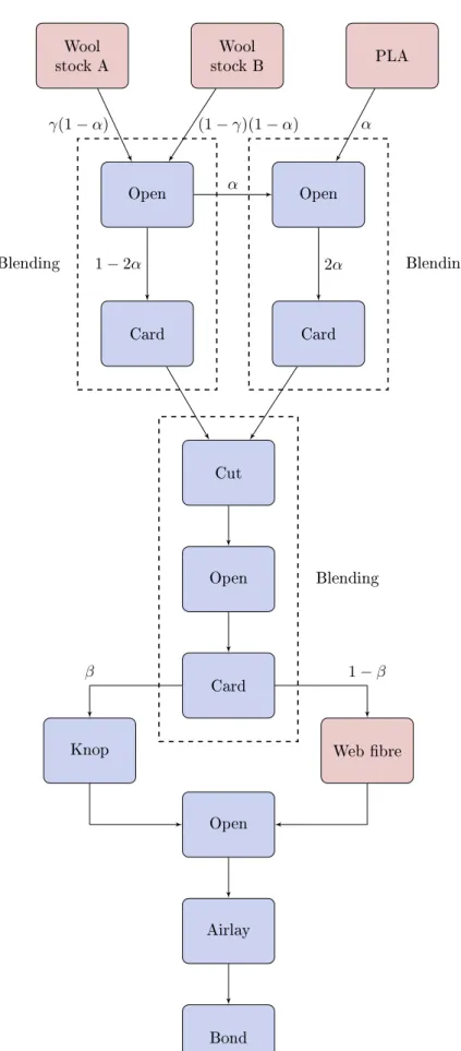
2.1 Outline of the general production process for knoppy web. . . 10
2.2 Schematic diagram of a carding machine with two workers. Example teeth are shown to illustrate their relative orientations. . . 14
2.3 Flow of bres at a carding point. . . 14
2.4 Markov chains with and without absorbing states . . . 14
2.5 States to be considered in the progress of the bre through the card, with 1 swift and 4 carding points (I to IV). (The workers and the strippers are not shown in the gure) [30] . 17 2.6 Constructing the bre withdrawal force from capstan forces. . . 17
2.7 Schematic illustration of a bre being removed from a tuft. The unshaded line indicates the shortest trajectory for the bre's withdrawal when constrained by neighbouring bres represented here by dots [34]. . . 17
2.8 Uncarded bre in contact with a carding element . . . 19
2.9 Geometry for calculating length fractions of cut bres [47] . . . 22
2.10 Comparison of distributions for a sound crossbred wool of medium length (barbe = 100 mm) [47]. . . 22
2.11 Probability densities resulting from the curring of slivers [44] . . . 23
2.12 Geometry for calculating length fractions of cut hooked bres . . . 27
2.13 The average displacement of a bre in a sliver as a function of the collecting power of the workers (pw) and the doer (pd). (ωi0= 10 s −1,ω t= 200 s−1,ωd= 10 s−1,rd= 0.4 m.) . . 27
2.14 The feedsheet of the opener. . . 28
2.15 The spinner that distributes the opened bres through the silo. . . 28
2.16 Schematic showing how the feed conveyor belt on the opener can be used to blend bres at small scales. . . 29
2.17 Drawframe passages with eight-sliver feed and a draft of eight. Example of blending by doubling and drafting: drawframe blending [28]. . . 31
2.18 A DOA airlay machine producing knoppy web. . . 34
2.19 Close-up of the outlet of the DOA airlay. . . 34
2.20 Schematic view of the DOA airlaying system [56]. . . 35
3.1 A van Wyk pile of rods. . . 46
3.2 The van Wyk bending element. . . 46
3.3 Contact of breB of orientation(θ0, φ0) withAof (θ, φ)and sweepings of the former on both sides of the latter, keeping the contact point and direction of the former unchanged [58]. 51 3.4 Direction of bre, and deformation of a bre element [70]. . . 51
3.5 Diagram of a slipping contact point [14]. . . 54
3.6 The forbidden length. . . 54
3.7 The evolution of strain energy within a van Wyk random bre assembly. . . 58
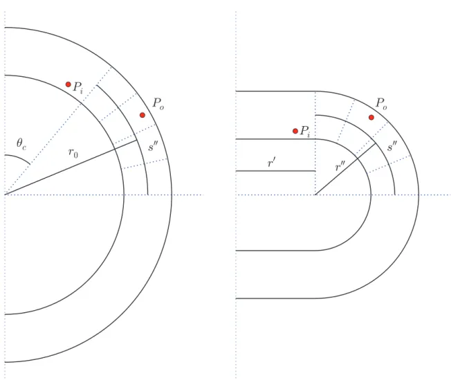
4.1 Schematics before and after compression for a knop of radius r0and shell thickness2h. . . 62
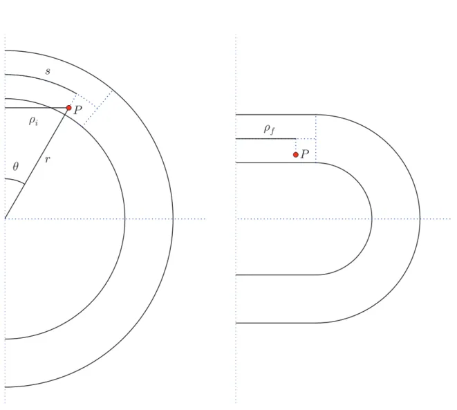
4.2 General mapping of points between the uncompressed sphere and the compressed sphere. 62 4.3 Mapping a point P between the uncompressed sphere and the inner region of the com-pressed sphere. . . 65
4.4 Mapping a point P between the uncompressed sphere and the outer edge region of the compressed sphere. . . 68
4.5 Surface and contour plots of UT. The lower blue line on the contour plot is r0 =c, and the upper blue line is r0= π2c. . . 74
4.6 Strain energy of a sphere under compression. . . 74
4.7 Surface and contour plots ofUMF. The blue line isr 0 =π 2c. . . 74
4.8 Surface and contour plots ofUMS. The lower blue line on the contour plot isr 0 =c, and the upper blue line is r0=r0sin (θc). . . 75
4.9 Surface and contour plots ofUB. . . 75
4.10 Energy components of a sphere under compression, plotted on (a) normal and (b) log-linear scales. Blue is 2UMF, green isUMS and red isUB. . . 75
4.11 Minimised sphere energy for a range ofr0. . . 77
4.12 Minimised sphere energy for a range ofh. . . 78
4.13 Minimised sphere energy for a range ofµk. . . 79
4.14 Compression of the basic knoppy web unit cell . . . 81
4.15 Basic knoppy web model . . . 85
4.16 Strain energy within the sphere, minimised alongr0. . . 85
4.17 Strain energy within the web, minimised alongr0. . . 86
4.18 Minimised basic unit cell energy for a range ofK. . . 86
4.19 Basic unit cell energy surfaces for a range ofK, minimised alongr0. . . . 87
4.20 Minimised basic unit cell energy for a range ofρw. . . 88
4.21 Basic unit cell energy surfaces for a range ofρw, minimised alongr0. . . 90
4.22 Minimised basic unit cell energy for a range oft0. . . 91
4.23 Basic unit cell energy surfaces for a range oft0, minimised along r0. . . 92
4.24 Compression of the modied knoppy web unit cell . . . 94
4.25 Modied knoppy web model . . . 96
4.26 Strain energy within the sphere, minimised alongr0. . . 96
4.27 Strain energy within the web, minimised alongr0. . . 98
4.28 Minimised modied unit cell energy for a range ofK. . . 98
4.29 Modied unit cell energy surfaces for a range ofK, minimised alongr0. . . 99
4.30 Minimised modied unit cell energy for a range ofρw. . . 100
4.31 Modied unit cell energy surfaces for a range ofρw, minimised along r0. . . 101
4.32 Minimised modied unit cell energy for a range oft0. . . 103
4.33 Modied unit cell energy surfaces for a range oft0, minimised alongr0. . . 104
4.34 Strain gradients within the web component during compression . . . 107
5.1 The various lls pre- (top) and post-compression (bottom). From left: down, goose feather, micro-knops,27µmwool knops, underbody knops. . . 111
5.2 The hexagonal assembly of cans, and the components for the pistons. . . 114
5.3 The fully-assembled can-and-piston compression aparatus. . . 114
5.4 Loosely lling a can with knops. . . 115
List of Figures xv
5.6 Can 1 lled with200 gof knops. . . 117
5.7 The compression assembly just after the weights were applied. . . 117
5.8 The compression assembly just before the weights were removed. . . 118
5.9 Knops from cans 3 and 4 being steamed for 30 seconds. . . 118
5.10 Apparatus and procedure for measuring the force-displacement curves of knops. . . 120
5.11 The evolution of piston heights over the duration of compression. . . 122
5.12 The evolution of piston heights as the compression weights were removed. . . 122
5.13 Knops after removal of the weight and pistons. . . 123
5.14 Side view of the unbonded knops from can 1 after removal of the weight and piston. . . . 123
5.15 Side view of the bonded knops from can 2 after removal of the weight and piston. . . 124
5.16 Knops from cans 1 and 2 just over an hour after they had been emptied into bags. . . 124
5.17 Force-displacement curves for the unsteamed knops. . . 126
5.18 Force-displacement curves for the unbonded knops. The pre-compression data is from leftover uncompressed knops. . . 127
5.19 Force-displacement curves for the bonded knops. The pre-compression data is from leftover uncompressed knops. . . 128
5.20 Production process for the knoppy web lots. . . 130
5.21 A Shirley Stiness Tester designed for testing webs . . . 134
5.22 Measuring with the Shirley stiness tester . . . 134
5.23 The compression apparatus for measuring force-displacement curves of knoppy web . . . . 137
5.24 Samples of Lot 6 (top) and Lot 2 (bottom), showing how the knops have been removed by the extra carding step. . . 137
5.25 SEM image of Lot 2 web . . . 139
5.26 SEM image of Lot 4 knop . . . 140
5.27 SEM image of Lot 4 web . . . 141
5.28 SEM image of Lot 1 web . . . 142
5.29 SEM image of Lot 3 knop . . . 143
5.30 Eect on the bending modulusqof (a) the knop:web ratio and (b) the PLA:wool ratio in the web. . . 145
5.31 Wash test on untreated wool . . . 147
5.32 Wash test on shrink-resist-treated wool . . . 147
5.33 Wash test on polyester . . . 147
5.34 Wash test on Lot 3 . . . 148
5.35 Wash test on Lot 5 . . . 148
5.36 Wash tests on other Lots . . . 148
5.37 Eect on force-displacement curves of varying the knop:web ratio. . . 150
5.38 Eect on force-displacement curves of varying the wool:PLA ratio. . . 152
5.39 Eect on force-displacement curves of additional carding. . . 153
5.40 The eect of web:knop ratio and t0 onρw. . . 158
5.41 A1 g sample of knops spread out on a surface for counting. . . 160
5.42 A group of six knops. . . 160
5.43 Fits of the knop model to data, shown on linear (left) and log (right) plots. Blue line is data, dotted line is t with the initial values of the parameters, red line is best t. . . 162
5.44 Fits of the brous knop model to data, shown on linear (left) and log (right) plots. Blue line is data, dotted line is intial t, red line is best t. . . 164
5.46 Fits of the modied knoppy web model and van Wyk model to data for Lot 1, shown on linear (left) and log (right) plots. Blue dots are the data points, dotted line is intial t,
red line is best t. . . 167
5.47 Fits of the modied knoppy web model and van Wyk model to data for Lot 2, shown on linear (left) and log (right) plots. Blue dots are the data points, dotted line is intial t, red line is best t. . . 168
5.48 Fits of the modied knoppy web model and van Wyk model to data for Lot 3, shown on linear (left) and log (right) plots. Blue dots are the data points, dotted line is intial t, red line is best t. . . 169
5.49 Fits of the modied knoppy web model and van Wyk model to data for Lot 4, shown on linear (left) and log (right) plots. Blue dots are the data points, dotted line is intial t, red line is best t. . . 170
5.50 Fits of the modied knoppy web model and van Wyk model to data for Lot 5, shown on linear (left) and log (right) plots. Blue dots are the data points, dotted line is intial t, red line is best t. . . 171
5.51 Fits of the modied knoppy web model and van Wyk model to data for Lot 6, shown on linear (left) and log (right) plots. Blue dots are the data points, dotted line is intial t, red line is best t. . . 172
5.52 Production process for overbody knoppy web. . . 177
5.53 Production process for underbody knoppy web. . . 178
5.54 Production process design for apparel knoppy web. . . 179
5.55 One of the baby mattresses produced from the underbody knoppy web. . . 180
5.56 The baby mattress contains three layers of underbody knoppy web sandwiched within a standard shell. . . 180
5.57 One of the single duvets produced from the overbody knoppy web. The duvet has been cut open to show the layers of knoppy web and fabric. . . 182
5.58 One of the quilted jackets produced from the apparel knoppy web. . . 182
5.59 Force-displacement curves for the unbonded overbody and underbody knops. . . 184
5.60 Force-displacement curves for overbody and underbody samples. . . 185
A.1 Congurations of a bre segment before (OA1i) and after (OA2i)z-directional compres-sion, and their projected chordsOB1i andOB2i on the xyplane [71]. . . 202
A.2 Contour plot of θc. . . 204
A.3 Recreation of Lee Carnaby Figure 2. . . 207
A.4 Recreation of Lee Carnaby Figure 4. . . 208
A.5 Recreation of Lee Carnaby Figure 5. . . 209
A.6 Recreation of Lee Carnaby Figure 6. . . 210
A.7 Surface and contour plots corresponding to the Lee Carnaby gures. . . 211
A.8 Energy vs. Compressional strain . . . 213
A.9 Energy vs. strain plot, and surface and contour plots, formax(a) =−0.1. . . 214
A.10 Energy vs. strain plot, and surface and contour plots, formax(a) =−0.1andmax(νa) = 3. 215
A.11 Energy vs. strain plot, and surface and contour plots, formax(a) =−1 andmax(νa) = 3. 216
A.12 Energy vs. strain plot, and surface and contour plots, formax(a) =−1 andmax(νa) = 3. 217
List of Tables
2.1 Properties for some of the bre types used in knoppy web production. . . 33
2.2 Number ratios for dierent bre type blends. . . 33
4.1 Sphere model parameters . . . 72
4.2 Parameters for the basic knoppy web model . . . 83
5.1 Pre- and post-compression bulks. The micro-knop bulks are calculated with a sample weight of 57.4 ginstead of56.7 g. . . 112
5.2 Measured bulks of the knops prior to compression . . . 113
5.3 Test compression of can 1. . . 116
5.4 Measured pre- and post-steam bulks of the unbonded (1, 3, 5) and bonded (2, 4, 6) knops. The percentage values for pre- and post-steam bulks are percentages of the measured bulks of leftover knops that had not been subjected to long-term compression (unbonded: 34 cm3g−1, bonded: 38 cm3g−1). The steam regain percentages are increases over the corresponding pre-steam bulks. . . 121
5.5 Overview of the various Lot variations, and the total wool fraction for each Lot. . . 131
5.6 Indicative shrinkage by area during bonding. . . 138
5.7 Inherent thermal resistance, warmth to mass and warmth to thickness ratios of Lots [95]. (µ= mean,σ= standard deviation,cv = coecient of variation) . . . 145
5.8 Stiness properties of the various Lots across the airlay . . . 145
5.9 Comparison of stiness properties . . . 145
5.10 Wash test results. * = the Lots were wash tested after 22 months in storage. . . 149
5.11 Wash test comparisons . . . 151
5.12 Calculated knop diameters . . . 161
5.13 Initial values and ranges of the tted parameters for the knop model . . . 161
5.14 Fitted values for the parameters of the knop model . . . 162
5.15 Initial values and ranges of the tted parameters for the brous knop model . . . 164
5.16 Fitted values for the parameters of the brous knop model . . . 164
5.17 Values of the constants for the modied knoppy web model . . . 167
5.18 Initial values and ranges of the tted parameters for the modied knoppy web model . . . 167
5.19 Initial values and ranges of the tted parameters for the van Wyk model . . . 167
5.20 Fitted values for the parameters of the modied knoppy web model . . . 168
5.21 Fitted values for the parameters of the van Wyk energy model . . . 168
5.22 Optimum specications for knoppy web blends. . . 175
5.23 Stiness properties of the various Lots across the airlay . . . 182
5.24 Weights and thicknesses used in calculation of gs. 5.60b and 5.60c. . . 183
5.25 Average rating change of the performance areas, and participant consensus [107]. The three consensus values represent the number of participants that rated the area higher (+), about the same (∼) or lower (-) after using the knoppy web duvet. . . 187
List of Terms
barbe The mean length of the bres of a sliver, calculated from the proportions by mass of the bres in the sliver.
batt A three-dimensional non-woven assembly of bres used for lining or insulating items.
hauteur The mean length of the bres of a sliver, calculated from the proportions by linear density of the bres in the sliver.
knop A small spherical cluster of bres.
knoppy web A batt containing some percentage of knops.
linear density The mean mass per unit length of bre or sliver.
sliver A long, untwisted ropelike bundle of bres with a roughly uniform thickness.
Chapter 1
Introduction
1.1 The wool bre
Wool is a textile bre with a history of use going back to antiquity [1]. It is naturally-grown, easily harvested, and can be produced sustainably. Once harvested it can be processed into a variety of forms, most notably into woollen and worsted yarns that are subsequently used in the production of fabrics and clothing. It is very much a niche bre in today's global textile industry, making up about 1.3% of total bre usage in 2014but this still amounts to around 1.2 million tons [2]. Aside from the above factors (and its abundance both within New Zealand and overseas), its continuing popularity can be attributed to the physical characteristics of the bre, which give rise to several useful properties:
• Felting: Wool bres have a two-component structure consisting of a central cortex with scaly
cuticlar cells surrounding it (g. 1.1). The scaly structure increases the friction between adjacent wool bres, and creates a ratcheting eect where bres will migrate in one direction through an assembly. This gives wool its felting ability, where the bres become irreversibly entangled and form mats of fabric.
• Insulation: The core itself has a further bilateral aspect responsible for its naturally-occurring
crimp [3, 4]. The presence of the crimp creates space between adjacent bres, trapping air within the overall structure. This makes wool particularly ecient at insulating.
• Hygroscopicity: Wool bres can absorb up to 30% of their weight in water without feeling damp [5].
Wool bedding products will therefore absorb moisture as the humidity of the surrounding air rises (such as from perspiration during sleep), and are perceived to be signicantly drier by users than cotton or polyester [6].
• Elasticity: Wool bres have remarkable elasticity when wetindividual bres can stretch up to 30%
and then return to their original length [7]. Dry wool is viscoelastic (length recovery is incomplete), and at room temperature shows stress-relaxation and creep [8]; however this can be reversed by immersion in water [7], or raising the temperature above the glass transition temperature [9].
• Fire-resistance: Compared to other commonly-used textile bres, wool is the most ame-resistant
because it has naturally high nitrogen and water content. It therefore has a very high ignition temperature and requires high levels of oxygen to sustain combustion [10]. Wool is also self-extinguishing, because it forms an insulating surface char as it burns that protects it from further oxidation [11, 12].
These properties make wool an ideal bre for everything from suits and hats to jerseys and carpets, depending on the particular bre diameter. However, these properties also pose several challenges for some types of products. In particular, the high felting ability and bending stiness create signicant issues when attempting to use wool in batting or other non-woven products.
1.2. KNOPS AND KNOPPY WEB 3
A wool batt or non-woven textile can be likened to a pile of logs, where the majority of bres are aligned perpendicular to the normal of the batt. When compression is applied perpendicular to the plane of the batt, energy is reversibly stored as bending strain in the wool bresbut there is also signicant bre-bre slippage [13, 14]. This slippage is essentially irreversible, due to bre locking by friction (between bres) and the aforementioned stress-relaxation of wool bres [15]. Over time, this leads to a considerable loss of bulk and compaction of the product. A common example is a wool underlay on a bed, which becomes atter and more uncomfortable the longer it is used. The physics underlying this situation has been extensively studied previously (see e.g. the mechanics of attening of carpets [16]).
Meanwhile, the bending strain stored within the wool bres enables the batt to support its own weight. This prevents the batt from eectively draping. Using the above example of a wool underlay, in addition to becoming hardened with use, the underlay tends to stick out the sides of the bed instead of hanging down.
Finally, wool products have a reputation for being impossible to wash safely in a washing machine. This is another side-eect of the high felting ability of wool. The repeated harsh working of wool products in a washing machine has a similar eect to the uniaxial compression considered above, but omnidirec-tionally. The eect is that the wool products felt and shrink under washing. Chemical treatments are available that can provide a shrink-resistant coating for the wool [1719]. For non-woven batts, however, this makes the situation worsethe washing machine destroys the integrity of the product (see g. 5.32 in section 5.4.3.6 for an example).
Down-lled products set the benchmark for performance in underbody and overbody uses. Down clusters are eective at insulating [20], have exceptional loft [20, 21], and can be washed (gently) without drastically aecting the integrity of the product [22]. Any manufacturer of wool-lled product who wants to compete in these sectors needs to be able to replicate the performance of down-lled products.
1.2 Knops and knoppy web
In the early 1980s, an alternative method and technology for processing wool bres was developed at the Wool Research Organization of New Zealand (WRONZ). The resulting product consists of small clusters of entangled wool bres called knops, and they present several key advantages over traditional brous masses:
• As outlined in the previous section, a brous mass is prone to attening after compression; repeated
compression cycling results in bulk loss. Knops have been qualitatively observed to be very resilient to compression; it is hypothesised that the reason for this is that knops are more elastic and experience a higher ratio of stored elastic energy to work against friction. Knops have a much lower percentage of bres aligned perpendicular to the direction of compression than a brous mass; therefore, more of the compressive strain is translated into bending strain of the constituent bres.
• Knops are small clusters of bre, usually less than 1cm in diameter, and are therefore not aected
by the long-range bending strength of a wool batta handful of knops has no concept of drape. A transversely isotropic product lled with these knops (or, for instance, a duvet) would therefore have little to no resistance to bending.
FibreTech New Zealand Ltd is a New Zealand company based in Woolston, Christchurch. It was established in 1985 by Mr. Peter Sheldon, specically to take the inital knop technology from WRONZ to the point where it could be leveraged commercially. Over the last several decades it has developed and rened the knop manufacturing process, and it is now possible to create knops to a wide variety of specications (e.g. size, softness, presence of a tail).
Figure 1.2: A pile of knops
1.3. TECHNICAL ISSUES 5
ratio of around 80:20 by weight, so for an equivalent total product weight there is much less web bre than a regular wool batt. The overall mechanical properties of knoppy web have been qualitatively observed by FibreTech New Zealand Ltd to be generally superior to a plain wool batt, specically in regards to resilience under compression.
Thermal bonding of non-woven fabrics has been widely used in industry as a means of adding cohesion and stability to products for several decades [23]. This is a process where a binding bre, powder or web is blended into the bre supply of the product, and then the end product is heated up above the melting point of the surface of the bonding bre. The binder polymer subsequently melts and sticks the surrounding bres together. For wool-based products (such as insulation batts) a bicomponent polyester bre is generally used for melt bonding [24]. This creates a scaold of polyester bonded to polyester brethe wool itself does not bond to the polyester.
FibreTech New Zealand Ltd has used thermal bonding to innovate further upon the base idea of a knoppy web: they blend a bicomponent polylactic acid (PLA) bre into the wool supply. Unlike other oil-based synthetic binder polymers, PLA is a biodegradable [25] thermoplastic derived from renewable resources [26], and is completely recyclable [27]. The bicomponent PLA bre that FibreTech New Zealand Ltd uses has a central PLA core with a melting temperature of around 160◦C, surrounded by a PLA
sheath with a melting temperature of around130◦C(g. 1.4a). Thus any PLA bres that are in contact
in the product (g. 1.4b) can be thermally bonded together when heated up to above 130◦C. At this
temperature, the outer sheath of the PLA bres melts but the integrity of the inner core remains (g. 1.4c); this allows PLA-PLA bonds to form between adjacent bres. Once cooled, the bres are joined with a rigid bond (g. 1.4d), creating a three-dimensional substructure within both the knoppy web and the knops themselves.
FibreTech New Zealand Ltd is able to manufacture knops containing a percentage of PLA bre, and by blending PLA into the web they can create a wool/PLA knoppy web product. FibreTech New Zealand Ltd uses a wool:PLA ratio of around 85:15 by weight for most products, but because the PLA bres are generally ner, the number ratio is signicantly closer to equality (this is discussed in more depth in section 2.5.5). When suciently blended, this means that a signicant fraction of wool bres will be separated from neighbouring wool bres by PLA bres.
In-house qualitative testing has indicated that the presence of PLA improves the performance of the end product, both under compression and in washing. It is hypothesised that the reason for this is multi-faceted:
• The PLA improves resilience against compression. The ner PLA bres build up less internal
energy when bent. But the three-dimensional bonded substructure within the knoppy web inhibits relaxation of this energy through bre slippage, which would occur more readily in the case of unbonded bres.
• The PLA forces separation of the wool bres and restricts bre migration, reducing its felting ability.
This is examined in section 2.3.2, and a mechanism is proposed in section 2.3.2.1.
1.3 Technical issues
The knoppy web products that FibreTech New Zealand Ltd have developed are in the process of being perfected. Prior to the start of this thesis, there were several open issues that required resolution in order for an eective commercial product to be developed and marketed.
(a) (b) (c) (d)
1.4. HYPOTHESES 7
are also not optimised for processing the ner PLA bre. An understanding was required of how the blending eciency aects the performance of the knoppy web.
Secondly, the knoppy web product needed to be optimised for dierent uses. As mentioned in the previous section, FibreTech New Zealand Ltd has developed the ability to customise knops to a variety of specications. Similar work needed to be done for the knoppy web product, as dierent uses have dierent requirements. The three key categories for knoppy web products are underbody, overbody and apparel. Underbody products need to withstand the repeated cycling of applied weight during normal usage (such as people sleeping); compression resistance and bulk retention are perceived to be the important properties. For overbody usage, bulk retention of the knoppy web under its own weight is key for warmth, and drape is important for comfort over the body. Bulk retention matters in apparel as well (again, for warmth), but much more important in the minds of consumers is softness of feel; no one wants a lumpy jacket.
Finally, an understanding of how the knoppy web works on a fundamental level was required. All prior understanding within the company had been gleaned from qualitative observations of trials. Each trial has a not insignicant cost, and FibreTech New Zealand Ltd only has a single production line. Hence, a piecewise iterative approach has underpinned the development of the knoppy web product thus far. Such an approach has been adequate for the early development stage, where there are too many variables to even quantify, let alone study. The knowledge/IP that the company has built up around the feel and handle of the knoppy web product has been important to current progress. However at this point in the product development process a more quantiable approach to the creation and analysis of the knoppy web product was required, to better determine the key factors in both manufacturing dierent styles of product, and reliably manufacturing the same style of product. At the same time, a theoretical analysis of knoppy web would provide greater understanding of the various mechanisms operating within the knoppy webfrom the eect of the knops on the overall product, to the bonded PLA substructure, to the eect that the PLA bres have on the separation of the wool bres and the felting ability. Such understanding is of particular importance when considering the requirement for usage optimisation outlined above. In addition, there are some markets where a solid scientic grounding for a product is highly benecial for marketing it to the end consumer, Japan being the notable example.
1.4 Hypotheses
The problem space that this PhD resides within was outlined in the previous section. From this problem space, and the existing work that had been done by FibreTech New Zealand Ltd, several hypotheses could be posed with regard to the benets that the wool/PLA knoppy web product might provide over the industry standard wool batt:
Hypothesis 1. A knoppy web has higher bulk retention than an equivalent weight of plain wool batt, due to less bre slippage and more compression energy being stored in the knops.
Hypothesis 2. A knoppy web has better drape than an equivalent weight of plain wool batt, due to the lower quantity of bres aligned within the plane of the batt.
Hypothesis 3. A product containing a non-zero percentage of bonded PLA bre has higher bulk retention than a product containing zero PLA bre, due to the stiness created by the bonded PLA substructure and the restriction on slippage of non-bonded bres.
These hypotheses form the base upon which this PhD is built. Validating (or invalidating) these hypotheses will provide a major contribution to the ongoing commercial development process that Fi-breTech New Zealand Ltd is undertaking, and by extension will benet the NZ wool industry inasmuch as the behaviour of these wool/PLA knop-based products will be better understood.
1.5 Thesis layout
The remainder of the thesis is presented as follows:
Chapter 2 examines the process of creating knoppy web as a whole, elucidates the physics which underlies the various processing steps, and explains the origins of the various properties.
Chapter 3 reviews the background literature necessary to understand the behaviour of the knoppy web, focusing on the physics of compression of spheres and random brous assemblies.
Chapter 4 presents the rst proposed model of the compression mechanics of a knoppy web. The model is based on a simplied model of the compression mechanics of an individual knop (motivated by observations made in chapter 3).
Chapter 5 presents the experimental work conducted throughout the product development process, ts the knoppy web model to experimental compression curves, and develops optimum knoppy web specications for several product categories.
Chapter 2
Physics of Processing
2.1 Introduction
Chapter 1 outlined the practical need for understanding the properties of knoppy web. An important part of this is understanding the process by which the knoppy web is created, and the variables that are available for tuning its properties. Knoppy web is envisaged as a versatile product, but that versatility is literally baked into the knoppy web at production time. Improvements in the factory's ability to reliably control product properties will directly translate into commercial success.
In this chapter, we outline the production process that has been developed for creating knoppy web. Each processing stage is then examined in turn, and the relevant physics is extracted and discussed. The theoretical insights are then linked back to the available control strategies.
Key original contributions in this chapter:
• A proposed mechanism for reduced bre migration in knoppy web (section 2.3.2.1).
• A previously unstated measure of the macroscale blending power of carding (section 2.5.1).
• An analysis of the number ratio of dierent bre types (section 2.5.5).
2.2 High level overview
Over the years that knoppy web has been developed, various processes have been identied for creating dierent products. Most of the intellectual property is in the recipe used; while there are some operational dierences, the majority of the process is well-established and generalised.
All knoppy web recipes require wool and PLA. Most recipes require at least two types of wool. Some recipes also use dierent types of PLA for the knops and web. There are three key quantities in the recipe:
1. The ratio of wool to PLA by weight in the knops.
2. The ratio of wool to PLA by weight in the web.
3. The ratio of knops to web by weight in the knoppy web.
Some recipes use dierent wool:PLA ratios in the knops and web. This usually coincides with a bulk stock of knops being produced, that is then used later in the production of several dierent knoppy web products. Other recipes use the same wool:PLA ratio for the knops and web; this is better for smaller production runs, because the bre blend can be created once and then split between knopping and web bre.
Wool
stock A stock BWool PLA
Open Open
Card Card
Cut
Open
Card
Knop Web bre
Open
Airlay
Bond
γ(1−α) (1−γ)(1−α) α
α
1−2α 2α
β 1−β
Blending Blending
Blending
2.3. CARDING 11
Figure 2.1 presents an example outline of a process for producing knoppy web using two wool com-ponents and a PLA component, with the same wool/PLA blend in the knops and web. αis the fraction of PLA by weight in the knoppy web,β is the fraction of knops by weight in the knoppy web, andγ is the ratios by weight of the two wool components. The process has the following steps:
1. The various wool components are weighed out and opened together to form the base wool stock.
2. The PLA fractionαis weighed out, and opened together with an equal weight of wool stock.
3. The 50:50 PLA:wool blend is then carded as one single lot, as is the remaining wool stock.
4. The two carded slivers are cut together.
5. The cut sliver blend is opened and carded to form a nal bre blend.
6. A fraction1−β of the bre blend is weighed out and put aside to form the web component.
7. The remainingβ bre blend is knopped.
8. The knops are opened together with the set-aside bre to form the knoppy web blend.
9. The blend is sent to the airlay machine to form the knoppy web product.
10. The knoppy web is bonded.
There are several distinct elements to the production process: carding, cutting, blending, knopping, airlaying and bonding. Each of these steps will now be considered in turn.
2.3 Carding
Carding is a fundamental step in the processing of raw wool into usable products. Wool naturally clumps together during its growth into staples, trapping dirt and resulting in a non-uniform distribution of bres. In order for wool to be a useful product component, it must be opened up to allow the bres to mix and dirt to fall out, then condensed into a form from which it can be eciently processed. Carding machines are the technological legacy of centuries of rening this process.
Figure 2.2 is a representative diagram of a carding machine, showing the various operating elements. The basic principle behind it (along with several similar wool processing devices [28]) is one of expansion and contraction:
• Fibre staple is fed into a slow-moving pair of rollers (the nippers,N), creating a controlled stream.
• Fibres from the nippers are picked up by a fast-moving drum (the swift), covered in small teeth
pointing in the direction of rotation. The dierence in speed between the nippers and the swift drastically decreases the density of the stream, forming a thin lm of bres on the surface of the swift.
• The bre is then collected by a slow-moving drum (the doer), which transports it to the exit of
the carding machine where it is collected as a long bundle (a sliver).
• Between the nippers and the doer are a series of smaller slow-moving drums (the workers) that
The teeth on the workers and doer point away from the direction of rotation, so that at the point where the swift and worker/doer meet (the carding point), the teeth pull on bres in opposite directions. This provides the force necessary to extract bres out of tufts, and also enables the swift to comb the bres on the workers and doer to provide a degree of straightening.
A crucial aspect of carding is its ability to separate and mix bres. This is important both to ensure that the resulting sliver is homogeneous, and to aid with blending bres from various sources; bulk wool bre can contain non-trivial variations in properties caused by both the growth environment and earlier processing stages. The separating and mixing comes from the action of the workers and doer. The workers remove bres from the swift and deposit them at an earlier point, which provides bre mixing within a nearby region of the web; meanwhile the doer collects only some of the bres from the swift, leaving the remainder to cycle past the workers again and mix with additional incoming bres from the feed sheet.
The eect of the workers and doer on the carding of wool was examined in a seminal paper by Martindale [29]. Figure 2.3 shows the paths that bres can take around a carding point. Martindale dened the collecting power of a worker as the fraction of bre reaching a carding point (the point of contact between the worker and swift) that is picked up by the worker, and also pointed out that the collecting power is equivalent to the probability that a bre approaching the worker would be picked up. The collecting power of the doer is dened similarly. Collecting power increases noticeably as worker speed increases, and is also aected by the position of the worker and the closeness of the worker to the swift [29]. The increase in collecting power with worker speed is attributed to the fact that more clean worker teeth are presented to the swift in a given interval, decreasing the chance of the worker teeth becoming clogged [29]. However, the increased removal rate of bres from the carding point also decreases their exposure to the combing eect of the swift, lowering the chance of lifted bres being re-captured.
The collecting power of a worker can be roughly determined by measuring the amount of bremi on
the worker (after stopping the card mid-production1). The collecting power of the worker is then
(2.1) pi=
νφ
i
miωi
+ 1
−1
where ν is the production feed rate, φi is the angle over which the collected bre was spread on the
worker, and ωi is the speed of the worker. This method is simplistic in that it ignores the bres that
escape the doer and cycle round again to the worker; thus it becomes less accurate as the collecting power of the doer decreases and more bre is left on the swift.
One of the factors that inuences a choice of bre blend is the particular cards available. The teeth on the card are obviously not easily altered, and the size of the teeth is generally considered an invariant per card. There are therefore limits on the diameters of bre that a card can eectively process:
• If the bres are too ne, tufts will not be eectively split apart, and the product will contain clumps.
The card will also lose more bres out the bottom.
• If the bres are too coarse, the teeth will be less eective at collecting the bres.
Most factories dealing with multiple bre diameters will have several cards to use at the appropriate times. However, when dealing with bre blends containing multiple bre diameters that are signicantly dierent (as can be the case for some knoppy web blends), a compromise must usually be decided on and accounted for; processing a blend on a dierent card could produce dierent results.
2.3. CARDING 13
2.3.1 Markov chains and the power of the doer
Carding is an inherently random processit is intractable to predict the exact form of the bres within a carded sliver, or their exact trajectory. Fortunately, stochastic mathematics (in particular, stochastic process theory) can be used to elucidate useful generalised information about the carding process. One branch of stochastic mathematics in particular is directly applicable to carding, due to the nature of the machinery: Markov process theory.
A Markov process is dened as a memoryless stochastic process. Stochastic means that the future state of the process cannot be explicitly determined, but instead can be predicted based on a set of well-dened probabilities; memoryless implies that these probabilities only depend on the current state, and not on how the system arrived at this state. Thus Markov processes are a special class of processes whose behaviour can be completely and precisely specied given any initial or intermediate state.
A Markov chain simplies the picture further, by restricting the system to a nite number of well-dened states. Figure 2.4(a) shows an example of a system with four states, and a set of possible transi-tions from one state to another. A Markov chain describes the probabilities of the system transitioning between these dierent states.
If a particular state has no outbound transitions (g. 2.4(b)), it is said to be an absorbing Markov state. For a system that contains absorbing Markov states, the probability that the system will transition into one of these states approaches 1 as time progresses.
Carding can be eectively modelled as a Markovian process. Monfort [30] showed that the card can be represented as a Markov chain, by considering that the carding points act as transitions between states. If we assume that a bre arriving at a carding point will be lifted or not at random, then the path the bre takes (being lifted by the worker or staying on the swift) clearly depends only on that bre arriving at the worker2. This is exactly the condition required of a Markovian process.
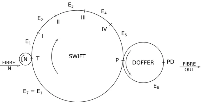
Figure 2.5 shows a schematic for a carding machine with four workers. similar to g. 2.2, but now labelled with various states E1 to E7. A bre will enter the swift at point T, after which it progresses around through the various carding points I to IV. At each point, the collecting power of the worker determines whether the bre is lifted by the worker or continues on. If the worker does lift the bre, it will deposit it ahead of its carding point. Therefore, each carding point can be represented by two transitions:
• A transition from the current state to the next state.
• A transition from the current state to itself.
For example, a bre in state E1 will reach carding point I and transition either to E1 (with probability equal to the carding power p1) or to E2 (with probability1−p1).
When a bre in state E5 reaches the doer (point P), it can transition either to E6 (on the doer) or E7. This is dierent to the carding points, because the doer never returns the bre to the swift. Thus, the doer state E6 can appropriately be labelled as an absorbing Markov state. The state E7 returns the bre to carding point I (the point T never removes bre, so there is no interaction); therefore it is equivalent to state E1.
The primary metric for the power of a card is the amount of time that bres spend inside it; bres will undergo more carding and blending the longer that they stay in the card. For the Markov chain shown in g. 2.5, the mean total number of states that a bre will transition through before exiting the card at point P is [30]
(2.2) t= 1
pd 1 + 4 X 1 1 qi ! ,
2.3. CARDING 15
where pi = 1−qi is the collecting power of carding pointi, and pd is the collecting power of the doer.
From this, it can be determined that the mean time a bre spends inside the card (from entering at point T to exiting at point P) is
(2.3) θ= 1
pd
(pdα+qd)
1 ωt + 4 X 1 pi
qiωi0 !
,
whereqd= 1−pd,αis the fraction of a turn of the swift corresponding to the arc from point T to point
P, ωt is the angular velocity of the swift, and ti = 1/ωi0 is the time it takes for a bre to travel from
carding point iaround the worker, stripper and swift before returning to carding pointi.
It is clear that that the blending power of a card is heavily inuenced by the doerthe mean time a bre spends inside the card is proportional to 1
pd. Increasing the collecting power of the workers does increaseω, but decreasingpd gives the workers more bites at the cherry.
2.3.2 Withdrawal force for a bre
The previous section showed how carding can be treated at an aggregate stochastic level, and how the behaviour of the card depends on the collecting power of the workers and the doer. On a micromechanical level, carding involves separating clumps of wool by pulling individual bres out of them with the hooks on the surface of the workers. The collecting power of the workers and doer is in part related to the probability that a bre will be hooked by the worker, but there is another factor that contributesthe strength of the bres and clumps.
The withdrawal force of a bre is the force that must be applied to a bre in order to remove it by its end from a clump of wool. The magnitude of this force depends on the number of bre-to-bre contacts along the trapped end of the bre, and the friction force at each contact point. Studies of the withdrawal force by Grosberg and Smith [31, 32] have shown that it is proportional to the pressure applied to the assembly, but that even at zero applied pressure there is an intrinsic withdrawal forceFW0caused by the inherent entanglement of the bres. Grosberg [31] gives the equation for the withdrawal force FW per
unit length of a single bre from an untwisted sliver as
(2.4) FW =µ0P+FW0,
where P is the external pressure exerted on the sliver, andFW0 is the value ofFW atP = 0. µ0 = 2µdφ
is a proportionality factor (with dimension length), in whichµis the coecient of friction,dis the mean bre diameter, andφis the packing fraction in the sliver.
Equation (2.4) assumes that the friction force at each contact point is the same. In reality this is not the case. A contact point forms when the bre wraps around a neighbouring bre. The angle about which the bre wraps around the contact point denes the friction force, by way of the capstan equation [33],
(2.5) Tload=Tholdeµφ,
whereTload is the applied tension to the bre,Tholdis the resulting force exerted on the other side of the
contact point,µis the coecient of friction between the bres, andφis the total angle swept out by all turns of the bre.
Figure 2.6 shows how eq. (2.5) can be applied to a bre. Tload at the contact point closest to the
pulled end of the bre is the withdrawal force FW, andThold at that point is equal toTload at the next
point. This continues along the bre until the second-to-last contact point, where Thold is equal to the
static friction force between the bre and the nal contact point (which it only contacts tangentially). If a bre has ncontact points, then the withdrawal force will be
(2.6) FW =Fn
n−1
Y
where Fn is the static friction force between the bre and the nth (nal) contact point, and φi is the
total angle swept out by all turns of the bre at theith contact point. Fn will depend on the bending
strain within the bre around contact pointn−1, as well as the distance betweenn−1 andn.
Another point that is not obvious from eq. (2.4) is that the withdrawal force depends on which end of the bre is being pulled. As mentioned in section 1.1, the high felting ability of wool comes from the ability of wool bres to ratchet through a brous assembly in the direction of the root. The ratcheting mechanism arises from anisotropy in the frictional force of the bre surface. The cuticular cells on a wool bre have a tooth-like shape, which causes the coecient of friction in the direction away from the root to be lower. In its natural environment where the bre is immobile, this acts as a self-cleaning mechanism; dirt particles will migrate out of a sheep's eece because less energy is required to overcome static friction. In wool products however, the bres themselves are mobile, and will move in the direction of their root for the same reason.
Finally, eq. (2.4) also assumes that no additional contact points are made as the bre is withdrawn; this is unlikely to be true in practice, at least for products in their initial unfelted state. Recently, Lee et al. [34] developed a model for describing the forces acting on a single bre as it is withdrawn from a tangled bre assembly. They dened the eective length of the bre as the length over which the friction forces act, and explained that this will rst increase and then decrease as the bre is withdrawn. Figure 2.7 shows a schematic representation of a bre being withdrawn from a xed tuft structure. As the bre begins to move, its trajectory converges on the shortest trajectory and the bre comes into active contact with neighbouring bres. It is these bres that dominate the withdrawal force, and their number increases as the slack in the bre is taken up. Once the entire bre is following the shortest trajectory, continued withdrawal decreases the eective length as the total length of bre remaining in the tuft decreases.
2.3.2.1 The eect of PLA on bre migration
Fibre migration occurs when bres incur transient tension due to movement or agitation of the assembly. This is functionally equivalent to applying a force to the end of a bre (or bre segment). If this transient force exceeds the withdrawal force for the bre (or bre segment), the bre will migrate. In section 1.2, it was hypothesised that one of the reasons for the observed performance benets of including PLA bres in knoppy web was that they reduce bre migration. We now use eq. (2.6) to propose a mechanism by which this could occur.
In a pure wool batt, the contact points are not xed in place and can be easily deected. The tension in the bre creates a lateral force on the contact points, from which the frictional force arises; however, this will also push the contacting bres sideways. This has the eect of straightening the bre's path, reducingφi at each deected contact point, which in turn decreases the capstan force at those points.
In a bonded knoppy web, the PLA substructure has two eects:
• It xes the position of the PLA bres. This inhibits their deection, meaning that a larger lateral
force is required to deect the PLA bres.
• It limits the potential range of deection of wool bres. In a well-blended brous assembly, the
wool bres will be eectively interwoven throughout the bonded PLA substructure. Deected wool bres would therefore be expected to quickly come into contact with nearby PLA bres.
Thus, the path of wool bres under tension will undergo far less straightening in the presence of the PLA; this lessens the reduction ofφi and the capstan force at each contact point. By eq. (2.6), the
2.3. CARDING 17
N
DOFFER
FIBRE
IN FIBREOUT
PD
SWIFT
P
I
II
III
IV
E
1E
7= E
1E
2E
3E
4E
5E
6T
Figure 2.5: States to be considered in the progress of the bre through the card, with 1 swift and 4 carding points (I to IV). (The workers and the strippers are not shown in the gure) [30]
Fw
F5
φ
1
φ
2
φ
3
φ
4
Figure 2.6: Constructing the bre withdrawal force from capstan forces.
We believe that the work of Lee et al. [34] is a rich area for new physics, because the bre migration observed with progressive washing could potentially be described as an aggregate of bre withdrawal processes. The mechanism described above could form the basis of a theory describing the micromechanics of washing brous assemblies. A similar idea could also be applied to the presence of knops in the knoppy web; their geometric constricting eect on their constituent bres could similarly increase the bre withdrawal force. Development of these ideas would be an ideal excellent potential basis for future work.
2.3.3 Fibre breakage
In section 2.3 we mentioned that the collecting power of a worker has a clear dependence on the worker speed. Increasing the worker speed therefore is an eective way to increase the level of carding and mixing. But it causes other problems, foremost of which is an increase in bre breakage.
Carnaby and Wood [36, 37] examined the physical conguration required to cause a bre break, and developed a transformation between the intial and nal length distributions based on the work of Meyer et al. [38]. Figure 2.8a shows the geometry: a carding element (such as a tooth on the swift) gripping a bre withing a clump. The fast-moving carding element (relative to the clump) applies a force to the bre. This force must be strong enough to overcome the withdrawal force for the short tail of the bre in order to card it. However, if the required withdrawal force is larger than the breaking load, the bre breaks.
Carnaby and Wood only considered breakages at the tooth, because this is where the majority of breaks occur [36]. However, in tender wool this is not necessarily the casecertain regions of the bre may be weaker than others. Carnaby and Burling-Claridge [35, 39] accounted for this by replacing the length-only distribution with a joint length-area distribution, representing the variable bre strength as a non-uniform cross-sectional area. Geometrically, the situation is unchanged (g. 2.8a), but the bre now breaks if the tension at any point along the bre (g. 2.8b) exceeds the local bre strength.
Breakages during carding (or at other stages in processing) will shift the length distribution of the bre stock towards shorter lengths. Several authors have examined the eect of carding bre breakages on bre length distributions, and section 2.4.1 covers this in more detail.
2.4 Cutting
As convenient as it would be for wool bre to be available in standard lengths, this is a luxury reserved for synthetic bres. Between natural growth and variations in shearing, as well as bre breakage during processing, bulk wool bre has a length distribution which will vary from batch to batch. Reliably determining this distribution is trivial in a laboratory setting [40]; the current standard measurement instrument is the Almeter, which uses a capacitance method to determine length distributions [41]. Expensive dedicated testing equipment is not however a justiable expense for most companies, and is impractical in most factory environments. A number of indices have been proposed over the years for characterising bre length distributions via simple and cheap tests (e.g. [42]), but these only provide indications of relative dierences. As it is, most commercial production lines do not have the time or resources to be able to test every batch of bales they receive.
Even when the characteristic length of a wool batch is suitable for a product, the bre length distri-bution can sometimes span several centimetres [43]. Wider distridistri-butions will have non-trivial fractions of longer and/or shorter bres, which can have a noticeable eect on the form and quality of the product. This is especially true for the knopping process; as outlined in section 2.6, the presence of longer bres can cause knops to be less well-formed, which is detrimental to the properties of knoppy web.
2.4. CUTTING 19
(a) Uncarded bre in a clump, in contact with a carding element [35].
(b) Fibre forces and tensions when in contact with the carding ele-ment [35].
![Figure 2.10: Comparison of distributions for a sound crossbred wool of medium length (barbe = 100 mm) [47].](https://thumb-us.123doks.com/thumbv2/123dok_us/9613126.1489607/43.892.87.761.567.1052/figure-comparison-distributions-sound-crossbred-medium-length-barbe.webp)
![Figure 2.17: Drawframe passages with eight-sliver feed and a draft of eight. Example of blending by doubling and drafting: drawframe blending [28].](https://thumb-us.123doks.com/thumbv2/123dok_us/9613126.1489607/52.892.299.636.463.741/drawframe-passages-example-blending-doubling-drafting-drawframe-blending.webp)