An Image Processing Based Method For Vehicle
Speed Estimation
Subhash Chand Agrawal, Rajesh Kumar Tripathi
Abstract— Vehicle flow estimation is an important part of traffic management system. It plays an important role in tracking systems, automatic video surveillance and also to avoid collision. This paper proposes a method to estimate the speed of vehicles on the highways and city areas. The proposed method can be effectively implemented to control the over speed vehicles and to found guilty in leading to traffic accidents. Each vehicle in the video recorded by the camera is identified. A bounding box is created on the identified vehicle and its centroid coordinates are marked. The analysis of speed is done using mathematical formulae which are embedded in the software. The existing research in this field has certain limitations. The first limitation is consumption of a lot of memory to store videos in the hard drive. The second limitation is inaccuracy of the system in unpleasant weather conditions such fog, haze, rain, and heavy winds, etc. Some systems failed to crate proper bounding box as it is necessary for accurate analysis of the motion of the vehicle and its speed. Another disadvantage is that shadow produced by vehicles on the different lanes of the road creates a fuss and the system detects the shadow too as a different object and creates a bounding box over it. There are other hardware based methods such as radar gun also. Cosine errors occurred when the direction of the vehicle and the radar gun doesn’t match. The objective of the proposed work is to develop a system which can provide the alternative to the radar based systems which can detect multiple vehicles at the same time. We have evaluated the proposed method on various traffic videos and found that the proposed method accurately detect the speed of a vehicle and outperforms many state-of-the-art approaches.
Index Terms— Speed estimation, Magnetic Sensor, Gaussian Mixture model, Background Subtraction, Multiple Vehicle detection, Vehicle counting
—————————— ——————————
1
I
NTRODUCTIONAn effective and consistent traffic surveillance system should be developed to control and manage the present scenario in the fast growing era of growth and development. It is an urgent need of hour to develop a traffic control and management system. This system can be utilized to enforce the law of vehicle’s speed in various states of India. Vehicle flow estimation is an important part of some traffic management system. The traffic flow shows the traffic state in a fixed time interval and helps to cope and control the other things. It is especially used when there is a traffic jam and speed of the vehicle creates havoc. Intelligent System for surveillance of vehicular traffic offers a context for the extraction of significant information of traffic statistics. An accurate and effective tracking system is the heart of such a system based on vision-based intelligence. Many works and efforts have been made in vehicle detection and speed estimation using image processing approach. A speed detection camera system (SDCS) is one of these systems that can replace traditional radar based systems and provides the efficient method to detect and track the objects. The magnetic sensors determine the speed of a vehicle on the basis of magnetic radiation. Their tracking technique did not use cameras and make a probable prediction of its motion. The spread of use of radar systems is affected negatively with the high cost and less accuracy of outputs. This motivated us to develop an alternative technique which may offer both accuracy and inexpensive solution.
2
R
ELATEDW
ORKMethod of speed estimation is categorized into two classes: Active methods (Radar and Lidar based methods) and passive methods (Image Processing based methods). The radar based systems use Doppler shift phenomenon. Several types of errors
may encounter during speed estimation which makes this method, a less accurate. When the direction of the radar gun is not on the direct path of the incoming vehicle, cosine error may occur.Shading (radar wave reflection from two different vehicles with distinctive heights), and radio interference errors are there. The cost of equipment is also one of the important reasons. Furthermore, RADAR sensors can track only one vehicle at a time. Second types are methods uses image processing and camera to measure the speed; they do not use any special hardware. Now we will discuss the some important research works of both types, done till date in the field of speed estimation
Ki and Baik [1] proposed a method based on double loop detector for measurement of vehicle speed. However, loop based method incurs error due to spacing between double loops, scanning time, irregular trajectories of vehicles and presence of multiple vehicles. For minimizing these errors in calculation of speed, author provided error filtering algorithm. Wei et al.[2] presented a vehicle detection method based on magnetic effect using iterative wavelet algorithm. It uses wireless magneto-resistive sensor based vehicle detection. They estimated the speed of a vehicle using clock synchronization method that minimizes the error. Mei and Li et al.[3] proposed a method for measuring speed of a railway vehicle. They used simplified inverse model to extract motion features by two sensors mounted on a bogie. The cross-correlation calculates the time delay in predicted motion between two wheel sets. This technique replaces the conventional wheel based estimation to overcome various difficulties incurred in wheel slip/slide conditions.Ibrahim et al.[4] presented a method to find the speed of a vehicle from single camera. This method consists of four phases. In the first phase, adaptive background subtraction algorithm is used to detect moving objects with three frame differencing. The second phase is consists of segmentation, labeling, etc. The third phases measures the speed of a vehicle based on number of frames passed by the vehicle in a particular scene. The fourth phase captures the picture of the vehicles that violates the speed limit. However, this method does not provide comparison with any of the existing method. Taghvaeeyan and Rajamani[5] developed a magnetic sensor based method for vehicle classification, counting and speed estimation. This uses wireless anisotropic
Subhash Chand Agrawal is currently pursuing PhD in computer science and Engineering from GLA University, Mathura, India. Email:
INTERNATIONAL JOURNAL OF SCIENTIFIC & TECHNOLOGY RESEARCH VOLUME 9, ISSUE 04, APRIL 2020 ISSN 2277-8616
1242 IJSTR©2020
magnetic devices which are placed next to the roadway and estimates traffic in adjacent lanes. Longitudinally spaced sensors are used to measure the speed based on cross-correlation. Vehicle classification is done through magnetic length and vertical magnetic height of the vehicle.KV et al.[6] proposed a method to estimate the speed without camera calibration. They segment the vehicle using frame subtraction and masking technique. Then, speed is calculated using timestamps of frames and segmented object.
Yang and Lei [7] also developed a method for vehicle classification and speed estimation using anisotropic magneto-resistive sensor. This method can be utilized in large cities where low speed congested traffic is there. Fixed threshold state machine algorithm is used to detect vehicle in a single lane. Sensor computes five features: direction of vehicle in which it is travelling, vehicle signals, average energy, energy, ratio of positive and negative energy in x axis and ratio of positive and negative energy in y axis. Thus detected vehicle is classified as motorcycle, car, bus, etc. based on classification tree module.
Chanawangsa et al.[8] presented a surveillance system using calibrated stereo cameras. Vehicle detection and tracking is performed in 2D space, and then depth and appearance features are incorporated into a tracking module suing 2D-3D approach. 3D coordinates of a detected vehicle help to estimate the speed of a vehicle. Momin et al.[9] proposed a method for detection a vehicle based on Haar classifier and Adaboost. Searching of vehicle is done through color, speed, direction and date and time. Zhu and Yu [10] proposed a method to deal with noise disturbances for on-street parking system. For this, they utilized cross-correlation technique in wireless magnetic sensor network. The speed of a vehicle is calculated using cross correlation between signals of two sensors, placed along the road at certain spacing. They achieved accuracy of 92%. Lovizon et al. [11] presented a method for speed measurement in urban roadways. They utilized an optimized motion detector and text detector which locate the license plate regions in the image. Features of license plate regions are calculated and tracked in consecutive frames of the video. Speed is measured by mapping vehicle trajectories into real world measures. The proposed system achieved precision and recall of 0.93 and 0.87 respectively.Wei et al.[12] presented a method for speed estimation based on tri-axial anisotropic magnetoresistive sensors and wireless sensor network. It consists of one master node and two sensor nodes placed along the road sides. These nodes measures the magnetic field disturbances caused by passing of a vehicle. The speed is calculated using maximum values and cross correlation of parts extracted from two sensor signals with accuracy of 97.92% with dynamic threshold. Gerat et al.[13] presented a method based on Gaussian mixture models, DBSCAN, Kalman filters and optical flow. The method is tested on different vehicles, driving positions etc. In paper [14], Avadi et al., estimated the speed based on movement pattern vector. They generated probability density function mathematical model of a vehicle’s speed. Their method is computational efficient method with error rate of 1.77%. Now a day, the methods used such as giant magnetoresistance (GMR) sensors suffers from many disadvantages. Such systems can detect only one vehicle at a time. Moreover, cosine error occurred when the direction of the vehicle and the radar gun doesn’t match. In this paper, we proposed an image processing based method to estimate the speed of a vehicle which can detect multiple objects in a single frame of the video. The
proposed method uses optical flow to find the changes in the intensity values across the frames. These apparent velocity components are then subjected to image processing techniques to obtain centroid of a vehicle. Afterward, the image coordinates of the centroid are mapped to world space. Using this information the velocity of the vehicle is estimated. The objectives of this paper are as follows:
1) To design an image processing based method using camera for speed measurement that can be utilized as speed trap system for the purpose of speed law enforcement and easy control over the traffic in overcrowded cities.
2) Data has to be taken at the straight roads only. 3) Detect multiple objects in a lane.
The remaining part of this work is structured as follows. Section 3 discusses the proposed methodology and the steps involved in detection of a vehicle and estimating its speed. The experimental results are discussed in section 4. Section 5 presents conclusions and future work.
3 P
ROPOSEDM
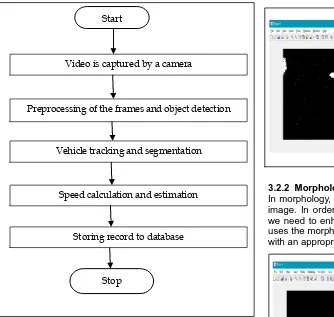
ETHODOLOGYAn overview of the proposed methodology is shown in figure 1. It consists of various phases: preprocessing, vehicle detection and tracking and speed estimation and storing record to database. In the first phases, captured video is preprocessed for further processing. In the second phases, moving vehicles are extracted from background subtraction and other techniques. The third phase estimates the speed of detected vehicles and finally estimated speed along with their timestamps are stored in the database for future reference.
3.1 Preprocessing
The preprocessing includes the following three sub-modules:
3.1.1 Capturing of Video Stream
The video will be captured by camera fixed at a pole on the road, which to be analyzed by the system. The video frames will be taken into consideration when the speed is calculated within stipulated time frame.
3.1. 2 Converting AVI file to RGB Intensity
The frames are extracted from the captured video and then each frame is converted to RGB image. Later, each frame has to be converted to gray scale image to speed up the processing.
3.1.3 RGB to Binary Image Conversion
INTERNATIONAL JOURNAL OF SCIENTIFIC & TECHNOLOGY RESEARCH VOLUME 9, ISSUE 04, APRIL 2020 ISSN 2277-8616
Fig. 1. Flowchart of process flow in the system
3.2 Vehicle Detection and Tracking This module includes following sub-modules:
3.2.1 Background Subtraction
Reference frame is a frame that does not consists of moving objects and is used to remove the background of the image as shown in figure 2. Background subtraction can be carried out by XOR operation or by Gaussian mixture model according to video resolution. In the proposed method Gaussian mixture model (GMM) is used. In GMM, cluster of moving pixel is formed that help to find moving objects in the video frames. We apply GMM on each frame of the video to get moving objects [15], [16]. In GMM, each pixel is represented by mixture of Gaussians. At any time t, a particular pixel is represented as follows:
Where coordinates (x0, y0) represent a pixel in pth frame. Probability distribution function is modeled by N Gaussian models and calculated as follows:
Where Xt is the pixel observed at time t, is the weight associated with pth Gaussian model with mean and standard deviation . is the Gaussian probability density function and calculated as follows:
The first C Gaussian distributions which exceed the threshold T are considered for background subtraction as follows:
Fig.2: Object Detection using background subtraction
3.2.2 Morphological Operations
In morphology, the image is processed based on shape of an image. In order to remove gaps generated along the edges, we need to enhance these moving edges. This enhancement uses the morphological operators such as dilation and erosion with an appropriate structural element as shown in figure 3.
Fig. 3. Results after applying morphological opening operations
3.2.3 Bounding Box Creation
After Gaussian mixture model, we find the cluster of the moving pixels. Afterwards, we surround that moving cluster into bounding box for each moving vehicle in each frame as shown in figure 4. Later on, we generate the centroid for every bounding box detected. Centroid will help us to reference each vehicle
Fig. 4. Bounding Box Creation over detected object Start
Stop
Video is captured by a camera
Preprocessing of the frames and object detection
Vehicle tracking and segmentation
Speed calculation and estimation
Storing record to database
, , ,
1
( ) ( | , )
N
t p t t p t p t
p
P X
X
,
p t
,
p t
,
arg min ( )
c
c p t
C
T1, 2, 3,... t { ( 0, 0, ) :1 }
X X X X I x y p p t (1)
(2)
(3)
(4)
,
p t
INTERNATIONAL JOURNAL OF SCIENTIFIC & TECHNOLOGY RESEARCH VOLUME 9, ISSUE 04, APRIL 2020 ISSN 2277-8616
1244 IJSTR©2020
3.2.4 Distance Normalization
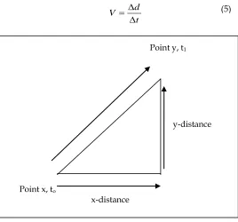
The general motion vector function is used to analyze the distance of moving vehicle from Point x to Point y as shown in figure 5. The average motion velocity V, of a moving object through a displacement (Δd) during a time interval (Δt) is described by the following formula:
Fig.5. Distance Approximation
If a moving vehicle travels from point x to point y at a distance of 100 meters in 5 seconds, the motion velocity is calculated as following.
t0 = 0 second; t1 = 5 seconds Δt = t1-t0 =(5-0) seconds= 5 second Δd = 100 meters
then, V = (Δd) / (Δt) = 100 / 5 = 20 meter/second 3.2.5 Centroid Calculation
The following formula is used to calculate centroid of each detected blob, given top left coordinates (x1, y1) and bottom right coordinates (x2, y2). Centroid calculation for detected vehicles is shown in figure 6.
1 2
( ) / 2
center
x x x
1 2
( ) / 2
center
y y y
Fig. 6. Centroid Calculation
3.2.6 Labeling Identified Objects
The identified objects in region of interest are labeled with a vehicle number tag. This provides each vehicle, a unique identification number. Later on, the label on each object is used as an identity to store recorded speed in the database.
3.3 Speed Calculation
In the proposed method, first we have to identify each vehicle in the video and then find their corresponding distance covered in consecutive frames. The proposed method tracks each vehicle and traces their centroid in upcoming frames to get the distance travelled by that vehicle. When vehicles arrive into the region of interest, in the video, their corresponding bounding boxes are created and then centroid of the each bounding box is generated. For every new vehicle arrival, we store its centroid value to the track. In addition, we update its centroid value in upcoming frames, and keep on updating its tracked value of centroid until that vehicle passes out by the video. We track all vehicles in a video simultaneously. Moreover, we store their centroid values into the track structure that we have created. The speed of each identified vehicle is calculated as:
tan /
Observed Dis ce Speed
framecount fps
Here, we use the following two cases: 1. If (Current.centroid == Initial Position )
We start the frame count for that vehicle and initialize the corresponding structure variable to hold the frame count. 2. If (Current.centroid == Final Position)
We store the final frame count in the respective variable and calculate the total frame traversed by that vehicle in order to reach from initial position to final position.
Total frames = Final_Frame_count – Initial_Frame_count Total distance = distance measured between two poles
tan ( )
_ /
Dis ce Speed i
total frames fps
Where Speed(i) denotes the speed of ith vehicle. fps is frame per second. Total_frames are the number of frames traversed over the distance.The speed is calculated in the number of pixel travelled per second unit, and then we change it into the km/hr unit by taking the actual distance measure of the area covered by the camera view. The pixel distance is later normalized to actual distance by calculating a normalization factor to map the actual distance in the pixel coordinates. The accuracy of detection of vehicle in the video frame depends upon the Gaussian mixture model parameters for training the frames for the background.
3.4 Storing Record to Database
All the vehicles captured in the video are numbered and their corresponding speed along with the vehicle number is stored in the database for the future reference. The generated log of the system can be saved at any instance of time. The time stamp is also attached with each saved record in the database. Figure 7 shows the running instance of log record of speed estimated over a scene point(shown in red and blue lines).
d V
t
y-distance
Point x, to
x-distance
Point y, t1
(5)
(6)
(7)
Fig. 7. Running instance of a vehicle
4 E
XPERIMENTALR
ESULTSThe area where system has to be installed needs to be first analyzed and the physical distance between initial entering position (the first frame where the camera detects the
vehicle
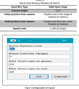
) and final exiting position (the last frame of detection) needs to be calculated and stored in the system’s database. The proposed system requires configuring of inputs such as camera height, initial position form camera, final position from camera and speed limit. These input values along with their valid range are illustrated in table 1 and its implementation in shown in figure 8. We have implemented the proposed method in MATLAB 2016a.TABLE 1
VALID AND INVALID RANGE OF INPUT
Fig.8. Configuration of Inputs
We captured the four video sequences of real traffic of resolution 640*360 with 30fps. The real distance of the highway that is covered by the view of camera is nearly 15 meter and the distance over which the car is tracked is 4
meter. In video, we have some vehicles travelling with different speed as illustrated in table 2.
TABLE 2
SPEED ESTIMATION ERROR
Video Sequence
Real Speed (Km/h)
Calculated Speed (Km/h)
Percentage error (%)
1 62 59.46 2.54
2 85 81.5 3.5
3 25 21.92 3.08
4 50 47.5 2.5
Mean % Error
2.91
The accuracy of detection of a vehicle in the video depends upon the Gaussian mixture model parameters such as number of frames for training the background. In the proposed approach, we have taken the starting 50 frames of the videos for training of background. Depending upon the no. of training frames the vehicle detection varies according to it
Fig. 9. Calculated Speed for Detected Vehicles
In the above figure 9, the speed of the vehicles and the number of frames traversed by each vehicle are shown. The accuracy of the result depends on how fast your processing system is. For instance, the highest detected speed is about 80 km/h which is about 4 km/h less than the actual speed of the vehicle. We have also compared the performance of the proposed method with existing methods on recorded video sequence as illustrated in table 3. The proposed method has achieved lowest speed estimation error among all the methods
5
C
ONCLUSIONA speed detection camera system has been developed to measure the speed of vehicles on the highways. The proposed system is capable to identify target vehicles in the presence of partial occlusions and ambiguous poses, and the cluttered background. The proposed method is capable to detect multiple vehicles simultaneously by drawing the surrounding bounding box. Experimental results show that the proposed
Input Box Type Valid Input range
Camera height 5-15
Initial position from camera Positive and in the range of camera (in meters)
Final position from camera Positive and less than initial Position (in meters)
Speed Limit 1-100 (in kmps)
TABLE 3
SPEED ESTIMATION ERROR
Method Ibrahim et al.[4]
KV et al.[6]
Great et al.[13]
The Proposed
Method
Percentage
INTERNATIONAL JOURNAL OF SCIENTIFIC & TECHNOLOGY RESEARCH VOLUME 9, ISSUE 04, APRIL 2020 ISSN 2277-8616
1246 IJSTR©2020
model gives relatively good performance. The accuracy of counting vehicles is 94%, although the vehicle detection was 100% in the presence of partial occlusions. The proposed method has a limitation that it fails when two vehicles are merged together and system treat them as a single entity. The future work will focus to overcome this limitation and to estimate speed on real-time live video sequences.
REFERENCES
[1] Yong-Kul Ki, Member and Doo-Kwon Baik, "Model for Accurate Speed Measurement Using Double-Loop Detectors," IEEE Transactions on Vehicular Technology, vol.55, no. 4, pp. 1094-1101, 2006. (IEEE Transactions)
[2] ShangGuan Wei, Wang Jian, Cai Bai-gen and Yin Qin, "An Novel Vehicle Detection Method Based on Wireless Magneto-resistive Sensor," In proceedings of 2009 Third International Symposium on Intelligent Information Technology Application, pp. 484-487, 2009. (Conference proceedings)
[3] T. X. Mei and H. Li, "Measurement of Absolute Vehicle Speed With a Simplified Inverse Model," IEEE Transactions on Vehicular Technology, vol. 59, no. 3, pp. 1164-1171, 2010. (IEEE Transactions)
[4] Osman Ibrahim, Hazem ElGendy, and Ahmed M. ElShafee, "Speed Detection Camera System using Image Processing Techniques on Video Streams," International Journal of Computer and Electrical Engineering, Vol. 3, No. 6, December 2011.
[5] Saber Taghvaeeyan and Rajesh Rajamani, "Portable Roadside Sensors for Vehicle Counting, Classification, and Speed Measurement," IEEE Transactions on Intelligent Transportation Systems, vol. 15, no. 1, pp. 73-83, 2014. (IEEE Transactions)
[6] Kiran Kumar KV, Pallavi Chandrakant, Santosh Kumar, Kushal KJ, " Vehicle Speed Detection in Video frames using Corner detection," In proceedings of Fifth International Conference on Signals and Image Processing, pp. 253-257, 2014. (Conference proceedings) [7] Bo Yang and Yiqun Lei, "Vehicle Detection and Classification for Low-Speed Congested Traffic With Anisotropic Magnetoresistive Sensor," IEEE Sensors Journal, vol. 15, no. 2, pp. 1132-1138, 2015.( IEEE Sensors Journal)
[8] Panya Chanawangsa, Jingyan Wan, Changxu Wu, Chang Wen Chen, "A Novel 2D-3D Hybrid Approach to Vehicle Trajectory and Speed Estimation," In proceedings of IEEE 17th International Conference on Intelligent Transportation Systems (ITSC), pp. 1906-1907, 2014. (Conference proceedings)
[9] Bashirahamad. F. Momin, Tabssum. M. Mujawar, "Vehicle detection and Attribute based search of vehicles in video surveillance system," In proceedings of International Conference on Circuit, Power and Computing Technologies [ICCPCT], 2015. (Conference proceedings) [10]Hongmei Zhu and Fengqi Yu, "A Cross-Correlation
Technique for Vehicle Detections in Wireless Magnetic Sensor Network," IEEE Sensors Journal, vol. 16, no 11, pp. 4484-4494, 2016. (IEEE Sensors Journal)
[11]Diogo Carbonera Luvizon, Bogdan Tomoyuki Nassu, and Rodrigo Minetto, "A Video-Based System for Vehicle Speed Measurement in Urban Roadways," IEEE Transactions on Intelligent Transportation Systems, vol. 18, no. 6, 2017. (IEEE Transactions)
[12]Qifan Wei and Bo Yang, "Adaptable Vehicle Detection and Speed Estimation for Changeable Urban Traffic With Anisotropic Magnetoresistive Sensors," IEEE Sensors Journal, vol. 17, no. 7, pp. 2021-2028, 2017. (IEEE Sensors Journal)
[13]Jozef Gerat, Dominik Sopiak, Milos Oravec, Jarmila Pavlovi cova, "Vehicle Speed Detection from Camera Stream Using Image Processing Methods," In proceedings of International Symposium ELMAR, pp. 201-204, 2017. (Conference proceedings)
[14]Saleh Javadi , Mattias Dahl , and Mats I. Pettersson, "Vehicle speed measurement model for video-based systems," Computers and Electrical Engineering, vol. 76, no. 2019, pp. 238-248, 2019.
[15]Stauffer C, Grimson W. ”Adaptive background mixture models for real-time tracking,” in Proc IEEE Conf on Comp Vision and Pattern Recognition, 1999, 246-252. (Conference proceedings)