Scholarship@Western
Scholarship@Western
Electronic Thesis and Dissertation Repository
9-11-2014 12:00 AM
Structural Response Analyses of Piezoelectric Composites using
Structural Response Analyses of Piezoelectric Composites using
NURBS
NURBS
Vijairaj Raj
The University of Western Ontario Supervisor
Anand V. Singh
The University of Western Ontario
Graduate Program in Mechanical and Materials Engineering
A thesis submitted in partial fulfillment of the requirements for the degree in Doctor of Philosophy
© Vijairaj Raj 2014
Follow this and additional works at: https://ir.lib.uwo.ca/etd
Part of the Applied Mechanics Commons, Energy Systems Commons, and the Structures and Materials Commons
Recommended Citation Recommended Citation
Raj, Vijairaj, "Structural Response Analyses of Piezoelectric Composites using NURBS" (2014). Electronic Thesis and Dissertation Repository. 2456.
https://ir.lib.uwo.ca/etd/2456
This Dissertation/Thesis is brought to you for free and open access by Scholarship@Western. It has been accepted for inclusion in Electronic Thesis and Dissertation Repository by an authorized administrator of
STRUCTURAL RESPONSE ANALYSES OF PIEZOELECTRIC
COMPOSITES USING NURBS
by Vijairaj Raj
Graduate Program in Engineering Science Department of Mechanical and Materials Engineering
A thesis submitted in partial fulfillment of the requirements for the degree of
Doctor of Philosophy
The School of Graduate and Postdoctoral Studies The University of Western Ontario
London, Ontario, Canada
ii ABSTRACT
Variational method deduced on the basis of the minimum potential energy is an efficient method to find solutions for complex engineering problems. In structural mechanics, the total energy comprises strain energy, kinetic energy and the work done by external and internal loads. To obtain these, the displacement fields are required as a priori. This research is concerned with the development of a numerical method based on variational principles to analyze piezoelectric composite plates and solids. A Non-Uniform Rational B-Spline (NURBS) function is used for describing both the geometry and electromechanical displacement fields. Two dimensional plate models are formulated according to the first order shear deformable plate theory for mechanical displacement. The electric potential varies non-linearly through the thickness, this variation is modelled by a discrete layer-wise linear variation.
The matrix equations of motion are reported for piezoelectric sensors, actuators, and power harvesters. Normal mode summation technique is applied to study the frequency response of displacement, voltage and the power output. A full three dimensional model is also developed to study the dynamics of piezoelectric sandwich structures. Simulations are provided for thick plates using plate theory and three dimensional models to verify the applicability of those theories in their regime. Newmark’s direct integration technique and a fourth order Runge-Kutta method were used to study the transient vibration. The variational method developed in this thesis can be applied to other structural mechanics problems.
iii
CO-AUTHORSHIP
iv
I dedicate this thesis to my parents Vijayalakshmi and Raj, and my dearest brother
v
ACKNOWLEDGMENTS
vi
Real happiness is cheap enough, yet how dearly we pay for its counterfeit.
vii
NOMENCLATURE
, , Natural coordinates in a mapped space.
{ϕ} Voltage vector.
1
n Number of control points.
NURBS Non Uniform Rational B-Spline.
k Order of the NURBS curve.
c b
a, , Plate dimensions.
w
v
u
,
,
Displacement components in x, y, z directions respectively.z
y
x
,
,
Cartesian coordinates of a point.{σ} Stress tensor.
[C] Elasticity matrix, in constitutive equation.
{ε׳} Strain tensor.
[e] Piezoelectric coupling matrix.
{D} Dielectric displacement tensor.
[∈ ] Dielectric matrix.
{E’} Electric field.
U Strain energy.
T Kinetic energy.
viii [M] Mass matrix.
[Km] Mechanical stiffness matrix.
[Kme] Electromechanical coupling matrix.
[Ke] Dielectric matrix.
}
{Q Electrical charge density.
}
{ Displacement vector.
}
{F Mechanical load.
t
Time.]
[C Proportional damping matrix, in equation of motion.
)
(
,k
iN
ith blending function of order kinspace.i
p
ith control point.i
ix
TABLE OF CONTENTS
ABSTRACT ... ii
CO-AUTHORSHIP ... iii
DEDICATION ... iv
ACKNOWLEDGEMENTS ... v
NOMENCLATURE ... vii
TABLE OF CONTENTS ... ix
LIST OF TABLES ... xiii
LIST OF FIGURES ... xiv
CHAPTER 1 ... 1
1. Introduction to the Thesis……….1
1.1 General introduction ... 1
1.2 Modelling techniques ... 2
1.3 Finite element method ... 5
1.4 Power harvesting ... 6
1.5 Introduction to NURBS ... 7
1.5.1 NURBS curves ... 8
1.5.2 Differentiation ... 11
x
1.5.4 NURBS Surfaces and Solids ... 13
1.6 NURBS - Analysis tool ... 15
1.7 Research Objectives ... 16
1.8 Thesis Organization ... 17
References ... 18
2 CHAPTER ... 26
2 Bending and Vibration Analyses of Skewed Trapezoidal Laminated Piezoelectric Plates Using NURBS ... 26
2.1 Introduction ... 26
2.2 Theoretical development ... 29
2.2.1 NURBS Representation of a quadrilateral domain. ... 29
2.2.2 First Order Shear Deformable Piezoelectric Plates. ... 31
2.2.3 NURBS Representation of displacement and electrical potential fields... 32
2.3 Variational method ... 33
2.4 Numerical results and discussion ... 35
2.4.1 Rectangular piezoelectric plate in cylindrical bending. ... 35
2.4.2 Simply supported symmetric isotropic trapezoidal plates. ... 36
2.4.3 Cantilevered skewed sandwich trapezoidal plates. ... 38
2.4.4 Cantilevered skewed sandwich trapezoidal plates: transient vibration ... 43
xi
References ... 52
3 CHAPTER ... 55
3 A Plate Model for Piezoelectric Vibrational Energy Harvesters Using NURBS ... 56
3.1 Introduction ... 55
3.2 Geometrical representation in NURBS. ... 59
3.3 Displacement Fields and Equation of Motion. ... 63
3.4 Numerical Results. ... 66
3.4.1 Static analysis on circular unimorph actuator: ... 66
3.4.2 Free vibration of laminated circular and elliptic sandwich plates: ... 68
3.5 Vibration energy harvesting ... 71
3.5.1 Sandwich plate power harvesters ... 72
3.6 Conclusion ... 79
References ... 80
4 CHAPTER ... 84
4. A Three Dimensional Formulation and Analysis of Piezoelectric Composites using NURBS ... 85
4.1 Introduction ... 84
4.2 Constitutive equation ... 86
4.3 NURBS Definitions of Geometry and Displacement – Electrical Fields ... 87
4.4 Equations of motion ... 89
xii
4.5.1 Static analysis of a trapezoidal cantilevered sandwich plate ... 92
4.5.2 Free Vibration Analysis of Rectangular Cantilevered Sandwich Plates. ... 94
4.5.3 Free Vibration Analysis of Cantilevered Piezoelectric Prismatic Bar ... 98
4.5.4 Transient vibration of cantilevered plate. ... 100
4.6 Closing Remarks ... 104
References ... 105
5 CHAPTER ... 108
5. Conclusion and Future Works ... 109
5.1 Introduction ... 108
5.2 Major Contributions to the Field of Study and Experience Gained. ... 110
5.3 Future works ... 111
References ... 112
APPENDIX ... 113
xiii
LIST OF TABLES
xiv
LIST OF FIGURES
Fig. 1.1 Local modification in a NURBS curve ... 10
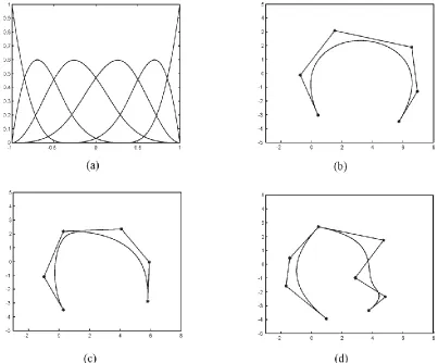
Fig. 1.2 NURBS curve and shape functions (a) Cubic NURBS basis functions for six control points (b) Parametric cubic curve for six control points, with uniform weights. (c) Parametric cubic curve for six control points, with non-uniform weights w = {113111} (d) Knot repetition, 0 C continuity at fourth control coefficient [-1 -1 -1 -1 -0.4 -0.4 -0.4 0.6 1 1 1 1]. ... 11
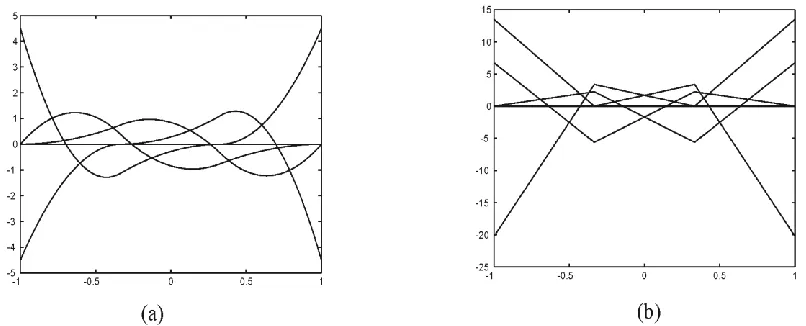
Fig. 1.3 Plot of the derivatives of blending functions: (a) First derivative (b) Second derivative ... 12
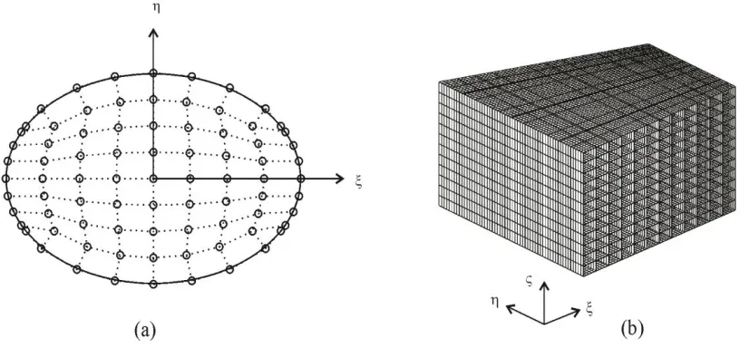
Fig. 1.4 A NURBS surface and solid (a) Two dimensional elliptic surface (b) three dimensional trapezoidal solid ... 14
Fig. 2.1 Quadrilateral plate. ... 29
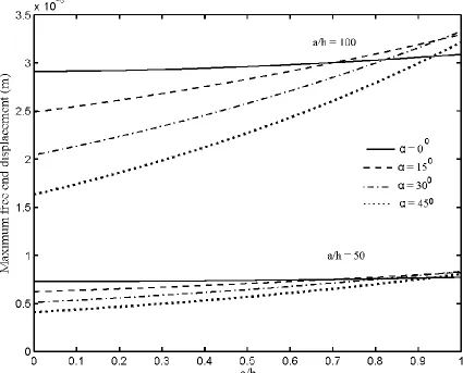
Fig. 2.2 Maximum free end displacement of a cantilevered sandwich plate, for an applied voltage of 100V and α= 0°,15°, 30° and 45°. ... 38
Fig. 2.3 Maximum free end transverse displacement of a sandwich plate, for a uniformly distributed load of 50kN/m2 and α= 0°, 15°, 30° and 45°. ... 39
Fig. 2.4 First five non-dimensional natural frequencies of a cantilever sandwich plate with various skew angles and aspect ratios. In (a) and (b) the variation of natural frequencies are shown for a/h = 50 and in(c) and (d) the natural frequencies are given for a/h = 100. ... 43
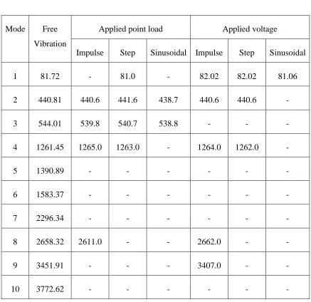
Fig. 2.5 Displacement history and FFT plots of cantilevered trapezoidal plate under various mechanical and electrical loads. (a) and (b) Half sine unit point load applied at the midpoint of the free end. (c) and (d) Unit point step load applied at the midpoint of the free end. (e) and (f) Impulse point load applied at the midpoint of the free end. (g) and (h) For an electrical step load of 50V. (i) and (j) Impulsive electrical load of 50V. ... 49
Fig. 3.1 Quadrilateral middle surface of an arbitrary shaped plate ... 60
Fig. 3.2 Cross section of piezoelectric sandwich plate. ... 68
xv
Fig. 3.4 Maximum displacement for an applied base acceleration of 3m/s2, (a) Straight
edge (b) curved edge ... 74
Fig. 3.5 Electrical output voltage as a function of non-dimensional frequency. (a) Straight edge (b) curved edge ... 75
Fig. 3.6 Electrical power output versus non-dimensional frequency (a) Rectangular plate (b) Curved edge ... 76
Fig. 3.7 Variation of power versus load resistance. ... 77
Fig. 3.8 Power versus proof mass ... 77
Fig. 4.1 Trapezoidal plate configuration. ... 92
Fig. 4.2 Variation of electric potential across the thickness ... 94
Fig. 4.3 First five mode shapes of cantilevered rectangular sandwich piezoelectric plate with a/h = 5 ... 97
Fig. 4.4 First six mode shapes of cantilevered prismatic piezoelectric bar ... 99
Fig. 4.5 Step response of cantilevered rectangular plate ... 101
Fig. 4.6 sinusoidal response of cantilevered rectangular plate ... 102
Fig. 4.7 Impulse response of cantilevered rectangular plate ... 102
1
CHAPTER
Introduction to the Thesis
1.1
General introduction
Piezoelectric structures play an important role in the field of sensors and actuators. The development of sensors and actuators mechanisms in itself is intrinsically prominent, as they are much imminent in quantifying a physical phenomenon. Piezoelectric materials, in particular found wide application as sensors in vibration control of structures. One of the reason being, the piezoelectric materials inherent ability to convert the small mechanical deformations in the scale of micrometer to a corresponding electrical output. In addition to that, piezoelectric materials have high hardness, a high linear relationship between input and output and their ability to be formed in to many different shapes.
mechanical action, it is called the “the direct piezoelectric effect”. Conversely if mechanical
strains are produced under an applied voltage, the effect is known as the “the converse effect”. Though the experimental studies quite effectively validated the piezoelectric effect
in crystals, the field of piezoelectricity remained more of a scientific accomplishment than finding a real world application. This scenario changed abruptly after world war one. Piezoelectric materials were used to transmit signals under water in devising resonators, actuators and transducers. The rest is history, one can find the proliferated application of piezoelectric materials in almost every field. Piezoelectric materials are used in multitude of disciplines like power harvesting, remote sensing devices, medical implants and recently the piezoelectric effects are even exploited in nanoscale devices.
In recent times, piezoelectric materials have been widely used as: sensors in structural health monitoring, a power source in micro scale electronic devices and actuators in micro pumps. In the beginning of the 19th century, the applications were different, piezoelectric materials were mainly used as transducers to transmit signal under water, sensors in measuring primarily force and acceleration. The materials used were also mostly naturally occurring crystals like quartz and Rochelle salt. However, over a period of time, more and more synthetic ceramics and synthetic piezoelectric materials were developed. These materials had very high electro mechanical coupling and can be tailored for specific application. Piezoelectric devices are finding more and more application at micro level vibration energy harvesters and nanoscale sensors.
1.2
Modelling techniques
1.3
Finite element method
Finite element method (FEM) played a vital role in the modelling of piezoelectric materials. Approximate numerical solutions can be obtained for complex shapes and different boundary conditions through FEM. This numerical method made the analysis possible for configurations which were not conceivable through analytical techniques. One of the earliest works on developing finite element technique for piezoelectric material was done by Allik and Hughes [25] in 1970. They presented the basic equations and variational formulation to arrive at the stiffness, mass, and electromechanical coupling matrices. Also a four node tetrahedron element was developed with each node having three displacement degrees of freedom and one electrical degree of freedom. Allik et al. [26] presented a finite element method for the dynamic analysis of piezoelectric solids. In their work, they employed an eight node hexahedron element with quadratic and quartic basis functions for displacement and electrical degrees of freedom. Ghandi and Hagood [27] used a similar type of eight node hexahedron element using isoparametric shape functions to analyze phase transitions in piezoelectric materials. This study also considered the response of piezoelectric materials subjected to a non-uniform electrical field. Lerch [28] presented a finite element technique for modelling piezoelectric transducers immersed in a fluid. He coupled the feedback from the fluid by using acoustic finite elements. Ha et al. [29] presented a three dimensional finite element formulation to study the static and dynamic response of laminated composite plates and verified their findings through experiments. Researchers focused more on two dimensional models in the early 1990’s. Primarily they
formulation for a four node element considering linear shape functions. A 20 node thermo piezoelectric element was developed by Koko et al. [33] to model smart composite structures. They also developed control algorithms using a linear quadratic regulator to obtain the feedback gain matrix. The finite element method was also used to study vibration control in smart structures [34,35]. Dietrich and Manfred [36] used a three dimensional formulation selecting reduced integration in the thickness direction to model thin plates. Numerical models were developed to study cracked piezoelectric materials in fracture mechanics by Qin [37]. The review article by Chen and Hasebe [38] documented the advancements in modelling cracks in piezoelectric materials. A brief survey reveals that finite element method is a method of choice to model piezoelectric materials as sensors and actuators. This is also true for applications like, active vibration control, structural health monitoring and fracture mechanics.
1.4
Power harvesting
structural resonance of the system. Sodano et al. [43] developed fundamental equations for a piezoelectric power harvesting beam and included proportional mechanical damping for the inherent structural damping and air resistance. The power generated from a piezoelectric device is defined by the electromechanical coefficient of the material. Two coupling modes denoted by 3-1 and 3-3 respectively, of piezoelectric materials were traditionally exploited in power harvesting. The coupling coefficient of the 3-3 mode is much higher than that of the 3-1 mode. However, the vibrational energy required to operate in 3-3 mode is much higher. Various configurations of power harvesters were developed to generate maximum power under given working conditions. Several techniques which included adding a proof mass, an L-shaped harvester to induce mores strain, a near triangular cantilever plate to create uniform strain, were reported in the literature [44, 45]. Zeng et al. [46] studied the positioning of piezoelectric materials in the structure for optimal power harvesting. They proposed optimal design realization for a cantilever bimorph type power generator. The influence of external circuits in power harvesting was studied by Zhu et al. [47]. They analyzed the influence of load resistance on the generated power from a cantilevered piezoelectric plate. Inman with other researchers [45, 48-51] published a series of papers on piezoelectric power harvesting. These notable studies included developing a beam model for piezoelectric powered harvesting with the effects of externally connected resistance on the power output. A cantilevered power harvester plate model was developed by Dutoit et al. [52] who provided non-dimensional power equations for beam and plate models.
1.5
Introduction to NURBS
polynomials, especially the Lagrange and Hermite polynomials. One of the main trade-offs while pursuing the conventional finite element method is that, the more complex the geometry is, the more complex becomes the meshing and the computational time increases. Analytical representation of curves, lines, surfaces and conics have different methods of representing each of them. This form of representation is easier for a designer to understand and get a physical context about the formulas and coordinates. However, it becomes counterintuitive as the geometry becomes complex. The intersection of surfaces with different forms of representation is often difficult to comprehend. Furthermore analytical methods are not suited to represent freeform curves and surfaces. Parametric curves like cubic splines, Bezier curves, B-splines and NURBS possess a common mathematical form for all type of geometrical entities. The data associated with parametric representation can be easily stored in matrix form and conversion between various formats is easier, i.e. the parametric curves can be manipulated and local changes made by simple steps. The first phase includes developing algorithms and programs for NURBS curves, surfaces and volumes, testing the numerical stability of programs, derivatives and numerical integration. The present work aims at proposing a computational method to study the dynamics of piezoelectric sensors, actuators, power harvesters using a numerical technique based on NURBS.
1.5.1 NURBS curves
A NURBS curve is given by Eq. (1.1) for a prescribed number of n+1 control points and order k.
n i i k i n i i i k i w N p w N C 0 , 0 , ) ( ) ( ) ( (1.1)where the vector piis an array of the control points, wi is the weights associated with the
control points and Ni,k are the B-Spline basis functions (blending functions or shape
relation as given in the book by Cox/de Boor [53]. In one-dimensional case, it starts with piecewise constants and from there it forms a pyramidal hierarchy.
else for
N i i
i 0 1 ) ( 1 0 , (1.2) ) ( ) ( )
( 1, 1
1 1 , 1 ,
i k
i k i k i k i i k i i k
i N N
N
The knot vector ξi is a set of parametric coordinates, which defines the limits of the knot
spans and is an array of non-decreasing distinct numbers, the only condition that it needs to satisfy. The first and last knot values are repeated ktimes to ensure that the curve passes through the first and last control points. The knot vectors are parameterized in –1 to 1 to take advantage of the Gauss integration and symmetric geometric conditions. The continuity of a curve depends on the order of the NURBS curve used. If the internal knot vectors are not repeated, the basis function is p1
C continuous, where p being the degree of
Fig. 1.1 Local modification in a NURBS curve
Figure 1.2(a) shows the shape (or blending) functions of a cubic curve corresponding to six control points with uniform weights. The curve and the open control polygon made by joining the control points are shown in Fig. 1.2(b). It can be inferred that the blending functions are always positive, Ni,k ≥ 0 for any parametric value. Fig. 1.2(c)
Fig. 1.2 NURBS curve and shape functions (a) Cubic NURBS basis functions for six control points (b) Parametric cubic curve for six control points, with uniform weights. (c) Parametric cubic curve for six control points, with non-uniform weights w = {113111} (d) Knot repetition, 0
C continuity at fourth control coefficient [-1 -1 -1 -1 -0.4 -0.4 -0.4 0.6 1 1 1 1].
1.5.2 Differentiation
The first derivative of a NURBS curve at a parametric value ξ can be obtained by normal differentiation [54] as given by the following equation.
n
i
i k i n
i
i i k i
w N
p w N
C
0 , 0
,
) (
) ( )
(
The first and second derivatives of the B-spline basis functions are obtained as, 1 1 , 1 1 , 1 1 1 , 1 , , ) ( ) ( ) ( ) ( ) ( ) ( ) ( i k i k i k i k i i k i k i i k i k i N N N N N
(1.4)
1 1 , 1 1 , 1 1 1 , ' 1 , , ) ( ) ( ) ( ) ( ) ( ) ( 2 ) ( i k i k i k i k i i k i k i i k i k i N N N N N
(1.5)
The above Eq. (1.4) and (1.5) pose a recursion relation with blending functions and its derivative of the k-1th order. For instance, the Fig. 1.3 below shows the first and second derivatives of the blending functions of a cubic curve with six control points. The first derivative of the blending functions forms piecewise parabolic Fig. 1.3(a) and the second derivative Fig. 1.3(b) results in linear functions.
Fig. 1.3 Plot of the derivatives of blending functions: (a) First derivative (b) Second derivative
Once the derivatives of the blending functions are obtained, the knot vectors are them modified to take account of the reduced curve order and the new NURBS curve can be obtained.
1.5.3 Numerical Integration
number of quadrature points (nint) has to be modified. In this thesis, the composite integral
of the curve is treated at each knot span level and a Gauss quadrature rule of 2n-1 is used, where n is the number of control points in each knot span. According to the work done by Stein [56], the number of integration points depends on the knot span and degree, providing an empirical relation nint =2×degree×knot span. For a cubic basis function with five-knot
spans, would result in 30 integration points. This seems to be a much higher number. In our convergent studies, the solution seems to converge even at half the number of the proposed integration points. Echter et al [57], studied the locking and unlocking characteristics of NURBS elements. In their work they used 3×3 Gauss points for quadratic, 3×4 Gauss points for cubic and a 3×5 scheme for a cubic and quartic NURBS basis functions. The number of integration points used in their work is quite acquiescent with the results obtained in our analysis. Hughes et al proposed a slightly modified form of Gaussian quadrature for NURBS basis functions [58]. They used a separate algorithm to modify the standard Gauss integration points and weights, considering higher order continuity Cp-1 and location of knot spans and their results are quite congruent with our results.
1.5.4 NURBS Surfaces and Solids
A NURBS curve is the fundamental entity in a model. Once a NURBS curve is constructed from a set of control points with predefined order and weights, a surface can be developed through more than one technique like sweeping, extruding and revolving. In the present context of the analysis, the quadrilateral surface of a plate is developed through number of surface patches. Let C1(ξ) is a kth order parametric curve in ξ direction and C2(η) is kth order curve in η direction. A surface patch S (ξ,η)is developed from the tensor product of two parametric curves as given in Eq. (1.6).
n i m j j i j i p R S 0 0 , , ( , ) ) ,( (1.6)
Fig. 1.4 A NURBS surface and solid (a) Two dimensional elliptic surface (b) three dimensional trapezoidal solid
1.6
NURBS - Analysis tool
One of the earliest application of splines and synthetic curves as basis functions for finite element analysis can be traced back to the1980’s, when synthetic curves like Bezier and B-splines were used as shape functions in Ritz method. FEA formulations using spline functions as the basis functions appeared in 1984, when Moore et al. [59] modelled a geometrically nonlinear quadrilateral shell element with linearized rational B-spline functions. Fan and Luah [60] used B-spline functions to model both geometry and displacements. Repeated knots were used to enforce discontinuity in beams and with that they performed free vibration analysis having multiple open cracks. In 1991. Singh [61] proposed a computationally efficient numerical technique for the vibration of shells using Bezier polynomials. In his work, fifth order Bezier functions were used to analyze rotationally symmetric shell structures. Gontier and Vollmer [62] in 1994, reported static analysis of beam undergoing large rotations using Bezier functions. The notion of using NURBS as a basis functions in finite element analysis was investigated by Hughes and co-workers. In 2005, they reported a comprehensive study on NURBS based isogeometric
boundary condition. By solving the variational form of the differential equation, numerical solutions that satisfy the enforced boundary condition are obtained and discussed.
1.7
Research Objectives
The present work encompasses on developing a numerical method based on variational technique using non-uniform rational B-splines (NURBS). The primary objectives includes,
1. To asses and understand various modelling techniques and applications of piezoelectric materials through a literature survey.
2. First part of the research is involved in understanding the fundamentals of computer aided design and NURBS. The second part is involved in developing algorithms and programs in MATLAB and C++ environment for curves and surfaces using NURBS.
3. Once the rudimentary programs to draw a NUBRS curve and surface were functional, programs were developed to study the dynamics of a beam and two-dimensional plate.
4. To study the bending and vibration characteristics of a sandwiched trapezoidal plate. The programs developed for two-dimensional plates are extended for a piezoelectric material.
5. To develop a generic computational model for vibrational energy harvesters using NURBS and find and analyse the frequency response of power and displacements. The plates are considered to have arbitrary or curved edges.
1.8
Thesis Organization
This thesis is organized in integrated article form. Presented in Chapter 1 are: a comprehensive literature review and general introduction to the thesis discussing various aspects of the present study. The study documents the previous research work available on piezoelectric materials, modelling techniques, finite element methods, power harvesting, non-conventional basis functions, and a general introduction to NURBS. Every effort is to present the review in a comprehensive form, yet it is difficult to review all the literature available on piezoelectricity.
Chapter two deals with studying the vibration characteristics of a trapezoidal sandwich plate. A variational method is presented on the statics and vibrations of composite first order shear deformable piezoelectric plates with NURBS functions. The results obtained using the computer codes developed in-house are validated by comparing them for the case of the cylindrical bending of piezoelectric plates. Results are also validated for the free vibration of isotropic trapezoidal plates. Maximum free end displacements are obtained for trapezoidal plates for various aspect ratios and skew angles. Forced vibration analysis is performed for various loading conditions.
Chapter three discusses about extending the variational method developed in previous chapter to plates with curved edges. A general curve fitting technique is also discussed in this section. The developed model is then validated by comparing the results of a circular sandwich plates with the data available in literature. In addition to actuator and sensor equations, equations are developed for a two dimensional power harvester, considering first order shear deformable plate theory and a layer-wise linear variation for electric potential. Frequency response curves were discussed for the power generated and displacements.
equations. Forced vibration analysis is performed on the system of equations represented in state-space form using a Runge-Kutta fourth order technique.
Finally a general concluding remarks, contribution to the field of study, and future work is presented in chapter 5 encompassing all the research work.
References
[1] J.D. Brownridge, S.M. Shafroth, “Using static charge on pyroelectric crystals to produce self–focusing electron and ion beams and transport through tubes,” Journal of electrostatics, 63 (2005) 249-259.
[2] F. Lack, “Observations on modes of vibration and temperature coefficients of quartz crystal plates,” Radio Engineers, Proceedings of the Institute of, 17 (1929) 1123-1141.
[3] D.A. Keys, “A piezoelectric method of measuring explosion pressures,” The London, Edinburgh, and Dublin Philosophical Magazine and Journal of Science, 42 (1921) 473-488.
[4] T.H. F, Linear piezoelectric plate vibrations, Plenum, New York, 1969.
[5] R. Mindlin, “High frequency vibrations of piezoelectric crystal plates, International Journal of Solids and Structures,” 8 (1972) 895-906.
[6] W.G. Cady., Piezoelectricity : An introduction to the theory and applications of electromechanical phenomena, Vols 1-2 ed., 1964.
[7] W.G. Cady, Piezoelectricity: An introduction to the theory and application of electromechanical phenomena in crystals, McGraw-Hill, 1946.
[8] W.P. Mason, Piezoelectric crystals and their application to ultrasonics, van Nostrand, 1950.
[10] R. Garcia Lage, C.M. Mota Soares, C.A. Mota Soares, J.N. Reddy, “Layerwise partial mixed finite element analysis of magneto-electro-elastic plates,” Computers & Structures, 82 (2004) 1293-1301.
[11] M. Cho, J. Oh, “Higher order zig-zag theory for fully coupled thermo-electric– mechanical smart composite plates, International Journal of Solids and Structures,” 41 (2004) 1331-1356.
[12] M. Ray, R. Bhattacharya, B. Samanta, “Exact solutions for static analysis of intelligent structures,” AIAA journal, 31 (1993) 1684-1691.
[13] N. Pagano, “Exact solutions for composite laminates in cylindrical bending, Journal of composite materials,” 3 (1969) 398-411.
[14] M.C. Ray, R. Bhattacharya, B. Samanta, “Exact solutions for dynamic analysis of composite plates with distributed piezoelectric layers,” Computers & Structures, 66 (1998) 737-743.
[15] P. Heyliger, S. Brooks, “Free vibration of piezoelectric laminates in cylindrical bending,” International Journal of Solids and Structures, 32 (1995) 2945-2960.
[16] P. Heyliger, “Exact Solutions for Simply Supported Laminated Piezoelectric Plates,” Journal of Applied Mechanics, 64 (1997) 299-306.
[17] A. Fernandes, J. Pouget, “An accurate modelling of piezoelectric multi-layer plates,” European Journal of Mechanics-A/Solids, 21 (2002) 629-651.
[18] A. Fernandes, J. Pouget, “Accurate modelling of piezoelectric plates: single-layered plate,” Archive of applied Mechanics, 71 (2001) 509-524.
[20] S. Dong, K. Uchino, L. Li, D. Viehland, “Analytical solutions for the transverse deflection of a piezoelectric circular axisymmetric unimorph actuator,” Ultrasonics, Ferroelectrics and Frequency Control, IEEE Transactions on, 54 (2007) 1240-1249.
[21] M.A. Askari Farsangi, A.R. Saidi, R.C. Batra, “Analytical solution for free vibrations of moderately thick hybrid piezoelectric laminated plates,” Journal of Sound and Vibration, 332 (2013) 5981-5998.
[22] Z. Zhong, E. Shang, “Three-dimensional exact analysis of a simply supported functionally gradient piezoelectric plate, International journal of solids and structures,” 40 (2003) 5335-5352.
[23] A. Jodaei, “3D elasticity solution for static analysis of functionally graded piezoelectric annular plates on elastic foundations using SSDQM,” Meccanica, 49 (2014) 215-237.
[24] F. Moleiro, C.M. Mota Soares, C.A. Mota Soares, J.N. Reddy, “Benchmark exact solutions for the static analysis of multilayered piezoelectric composite plates using PVDF,” Composite Structures, 107 (2014) 389-395.
[25] H. Allik, T.J. Hughes, “Finite element method for piezoelectric vibration,” International Journal for Numerical Methods in Engineering, 2 (1970) 151-157.
[26] H. Allik, K.M. Webman, J.T. Hunt, “Vibrational response of sonar transducers using piezoelectric finite elements,” The Journal of the Acoustical Society of America, 56 (1974) 1782.
[27] K. Ghandi, N.W. Hagood, “Nonlinear finite element modeling of phase transitions in electromechanically coupled material,” Symposium on Smart Structures and Materials, International Society for Optics and Photonics, 1996, pp. 121-140.
[29] S.K. Ha, C. Keilers, F.-K. Chang, “Finite element analysis of composite structures containing distributed piezoceramic sensors and actuators,” AIAA journal, 30 (1992) 772-780.
[30] J. Kim, V.V. Varadan, V.K. Varadan, “Finitie element modelling of structures including piezoelectric active devices,” International Journal for Numerical Methods in Engineering, 40 (1997) 817-832.
[31] J. Kim, V.V. Varadan, V.K. Varadan, X.-Q. Bao, “Finite-element modeling of a smart cantilever plate and comparison with experiments,” Smart Materials and Structures, 5 (1996) 165.
[32] D.A. Saravanos, P.R. Heyliger, D.A. Hopkins, “Layerwise mechanics and finite element for the dynamic analysis of piezoelectric composite plates,” International Journal of Solids and Structures, 34 (1997) 359-378.
[33] T.S. Koko, I.R. Orisamolu, M.J. Smith, U.O. Akpan, “Finite-element-based design tool for smart composite structures,” Smart Structures and Materials' 97, International Society for Optics and Photonics, 1997, pp. 125-134.
[34] U. Gabbert, T. Nestorovic-Trajkov, H. Koppe, “Finite element-based overall design of controlled smart structures,” in, John Wiley and Sons Ltd, 2006, pp. 1052-1067.
[35] C. Chang-qing, W. Xiao-ming, S. Ya-peng, “Finite element approach of vibration control using self-sensing piezoelectric actuators,” Computers & Structures, 60 (1996) 505-512.
[36] D. Braess, M. Kaltenbacher, “Efficient 3D‐finite element formulation for thin mechanical and piezoelectric structures,” International journal for numerical methods in engineering, 73 (2008) 147-161.
[38] Y.-H. Chen, N. Hasebe, “Current understanding on fracture behaviors of ferroelectric/piezoelectric materials,” Journal of intelligent material systems and structures, 16 (2005) 673-687.
[39] M. Umeda, K. Nakamura, S. Ueha, “Analysis of the transformation of mechanical impact energy to electric energy using piezoelectric vibrator,” Japanese Journal of Applied Physics, 35 (1996) 3267-3273.
[40] C.B. Williams, R.B. Yates, “Analysis of a micro-electric generator for microsystems,” Sensors and Actuators A: Physical, 52 (1996) 8-11.
[41] G. Poulin, E. Sarraute, F. Costa, “Generation of electrical energy for portable devices: Comparative study of an electromagnetic and a piezoelectric system,” Sensors and Actuators A: Physical, 116 (2004) 461-471.
[42] M. Goldfarb, L.D. Jones, “On the efficiency of electric power generation with piezoelectric ceramic,” Journal of Dynamic Systems, Measurement, and Control, 121 (1999) 566-571.
[43] H.A. Sodano, G. Park, D. Inman, “Estimation of electric charge output for piezoelectric energy harvesting,” Strain, 40 (2004) 49-58.
[44] W.G. Li, S. He, S. Yu, “Improving power density of a cantilever piezoelectric power harvester through a curved L-shaped proof mass,” Industrial Electronics, IEEE Transactions on, 57 (2010) 868-876.
[45] A. Erturk, J.M. Renno, D.J. Inman, “Modeling of piezoelectric energy harvesting from an L-shaped beam-mass structure with an application to UAVs,” Journal of intelligent material systems and structures, (2008).
[47] M. Zhu, E. Worthington, J. Njuguna, “Analyses of power output of piezoelectric energy-harvesting devices directly connected to a load resistor using a coupled piezoelectric-circuit finite element method,” Ultrasonics, Ferroelectrics and Frequency Control, IEEE Transactions on, 56 (2009) 1309-1317.
[48] A. Erturk, D.J. Inman, “A distributed parameter electromechanical model for cantilevered piezoelectric energy harvesters,” Journal of Vibration and Acoustics, 130 (2008) 041002.
[49] A. Erturk, D.J. Inman, “Issues in mathematical modeling of piezoelectric energy harvesters,” Smart Materials and Structures, 17 (2008) 065016.
[50] S.C. Stanton, A. Erturk, B.P. Mann, D.J. Inman, “Nonlinear piezoelectricity in electroelastic energy harvesters: modeling and experimental identification,” Journal of Applied Physics, 108 (2010) 074903.
[51] A. Erturk, D. Inman, “Broadband piezoelectric power generation on high-energy orbits of the bistable Duffing oscillator with electromechanical coupling,” Journal of Sound and Vibration, 330 (2011) 2339-2353.
[52] N.E. Dutoit, B.L. Wardle, S.-G. Kim, “Design considerations for MEMS-scale piezoelectric mechanical vibration energy harvesters,” Integrated Ferroelectrics, 71 (2005) 121-160.
[53] L.A. Piegl, W. Tiller, The NURBS book, Springer, Berlin ; New York, 1997.
[54] D.F. Rogers, An Introduction to NURBS with Historical Perspective, Morgan Kaufmann Publishers, 2001.
[55] R.N. Goldman, “Blossoming and knot insertion algorithms for B-spline curves,” Computer Aided Geometric Design, 7 (1990) 69-81.
[57] R. Echter, M. Bischoff, “Numerical efficiency, locking and unlocking of NURBS finite elements,” Computer Methods in Applied Mechanics and Engineering, 199 (2010) 374-382.
[58] T.J.R. Hughes, A. Reali, G. Sangalli, “Efficient quadrature for NURBS-based isogeometric analysis,” Computer Methods in Applied Mechanics and Engineering, 199 (2010) 301-313.
[59] C.J. Moore, T.Y. Yang, D.C. Anderson, “A new 48 d.o.f. quadrilateral shell element with variable-order polynomial and rational B-spline geometries with rigid body modes,” International Journal for Numerical Methods in Engineering, 20 (1984) 2121-2141.
[60] S.C. Fan, M.H. Luah, “Spline finite element for axisymmetric free vibrations of shells of revolution,” Journal of Sound and Vibration, 132 (1989) 61-72.
[61] A.V. Singh, “On Vibrations of Shells of Revolution Using Bezier Polynomials,” Journal of Pressure Vessel Technology, 113 (1991) 579-584.
[62] C. Gontier, C. Vollmer, “A large displacement analysis of a beam using a CAD geometric definition,” Computers and Structures, 57 (1995) 981-989.
[63] T.J.R. Hughes, J.A. Cottrell, Y. Bazilevs, “Isogeometric analysis: CAD, finite elements, NURBS, exact geometry and mesh refinement,” Computer Methods in Applied Mechanics and Engineering, 194 (2005) 4135-4195.
[64] J.A. Cottrell, T.J.R. Hughes, A. Reali, “Studies of refinement and continuity in isogeometric structural analysis,” Computer Methods in Applied Mechanics and Engineering, 196 (2007) 4160-4183.
[65] A. Reali, “An Isogeometric Analysis approach for the study of structural vibrations,” Journal of Earthquake Engineering, 10 (2006) 1-30.
[67] H.J. Kim, Y.D. Seo, S.K. Youn, “Isogeometric analysis for trimmed CAD surfaces,” Computer Methods in Applied Mechanics and Engineering, 198 (2009) 2982-2995.
[68] Y. Bazilevs, L. Beirão Da Veiga, J.A. Cottrell, T.J.R. Hughes, G. Sangalli, “Isogeometric analysis: Approximation, stability and error estimates for h-refined meshes,”
2
CHAPTER
Bending and Vibration Analyses of
Skewed Trapezoidal Laminated
Piezoelectric Plates Using NURBS
2.1
Introduction
theories was published by Saravanos and Heyliger [11]. Erturk and Inman presented the modelling and applications of piezoelectric plate as an energy harvester. Their work involved in developing various plate and beam models, optimizing the shape and experimental verifications for piezoelectric energy harvesters [12].
Eer Nisse [13] developed a method to examine the short circuit resonant properties of piezoelectric vibrators. It was shown that results had the agreement of better than three percent with the published experimental data for the lowest eight resonant frequencies of fully electroded thick barium titanate discs. Holland and Eer Nisse [14] explored the variational method further by treating some large classes of problems. Allik and Hughes [15] developed a finite element formulation for piezoelectricity and reported a tetrahedral element for three dimensional piezoelectric models.
Hwang and Park [16] presented a finite element formulation using classical laminated plate theory in the Hamilton’s energy functional. Lee and Moon [17] developed
a set of piezo-polymer devices by using polyvinylidene difluoride (PVDF) with different ply layouts. An equivalent single layer theory with third degree interpolation through the thickness for mechanical displacement components was developed by Mitchell and Reddy [18] for piezoelectric composites. They applied discrete linear interpolation for the potential function and solved equations by applying Navier’s method for the static deflections and natural frequencies of symmetric simply supported plates embedded with piezoelectric materials. Kim et al. [19] used flat shell elements for the plates structure and three dimensional elements for MEMS scaled piezoelectric devices.
linear interpolation through the thickness for the electric potential function. Kapuria and Kulkarni [24] developed an element with four physical nodes and one electrical node based on the zigzag theory. They also studied the transient response analysis of skewed sandwich plate under step and pulse type electromechanical excitations. The performance of this method was assessed by comparing results from the analysis with 3D finite element using ABAQUS. Loja et al. [25] studied the static and free vibration analyses of sandwich plates composed of functionally graded core and piezoelectric skins by B-spline finite strip method. This selective literature review, pertaining to the mechanics of plates, piezoelectricity and composites reveals that in most cases the studies have been limited to rectangular shapes. Also most of the work provided solution techniques for a certain class of problems. It is also realized that apart from finite element technique a general methodology to study the piezoelectric plate structures as an actuators and sensors are few and far between.
of skewed trapezoidal cantilevered sandwich plates with piezoelectric skins are also presented and discussed. The transient vibration analysis is performed by the Newmark’s direct integration method for sandwich plates under different loadings such as impulsive, short duration step and half sine wave. The fast Fourier transforms (FFTs) of the transient responses are studied to determine the contributing natural frequencies.
2.2
Theoretical development
2.2.1 NURBS Representation of a quadrilateral domain.
A quadrilateral domain as shown in Fig. 2.1 is chosen aiming to propose a formulation that can be easily applied to study plate bending and vibration problems of many different shapes. The mid-plane geometry is defined parametrically using ξ and η as coordinates along the edges. Since NURBS offers a comprehensive mathematical representation for all types of conics and arbitrary shapes, the mathematical modelling can be dealt in a unified way for various plate shapes.
The mathematical description of a NURBS curve contains a set of basis functions, degree and control points/coefficients [27]. The NURBS curve can be defined parametrically in ξ direction by n control points and kth degree as given in Eq (2.1).
i k i n i p R
C( ) , ( )
0
and
i k i n i i k i k i w N w N R ) ( ) ( ) ( , 0 , ,
. (2.1)
Here, Ri,k(ξ) is the rational basis functions on ξ ∈ [-1, +1], pi is a vector of n+1 control
points, wicontains the weights and Ni,k(ξ) is the kth degree B-spline basis functions, which
can be evaluated by applying recursive relation given by Cox and de Boor [27].
else for
N i i
i 0 1 ) ( 1 0 , (2.2) ) ( ) ( )
( 1, 1
1 1 , 1 ,
i k
i k i k i k i i k i i k
i N N
N (2.3)
Knot vector ξi is a set of parametric coordinates that defines the limits of the knot spans.
Depending on the degree, each shape function is non-zero only over a certain span. The desired order of continuity is attainable by repeating the knots at a particular nodal point over the knot span. An open uniform knot vector has the following form,
1 , 2 1 , 1 1 0 , 0 k n i n k n n i k k i k i i
(2.4)
1 1 1 1 ... ,... 1 , ...., ,... , 0 . ,... 0 k n k k
i
(2.5)
computation. Similarly, the NURBS curve is constructed in the η direction with different number of control points. Thus, using (n+1) control points in ξ direction and (m+1) in η direction, a control net of p = (n+1) × (m+1) grid points is defined below in Eq. (2.6).
j i j i m j n i p R
S , ,
0 0 ) , ( ) , (
(2.6)In the above, wi,j are the weights associated with pi,j and Ri,j(ξ,η) is given as
j i k j j i m j n i j i k j j i j i w N N w N N R , , , 0 0 , , , , ) ( ) ( ) ( ) , (
(2.7)The blending function Ri,j(ξ,η) can be used in Eq. (2.6) along with the Cartesian coordinates
of the grid points to define the mid-plane surface of the plate.
2.2.2 First Order Shear Deformable Piezoelectric Plates.
In this section, the governing equations are developed beginning with the very basic equations for the first order shear deformable plates. The plate is assumed to be made from the fiber reinforced composites with piezoelectric material as insert and the rotary inertia and transverse shear are included in the formulation. Piezoelectric materials are inherently anisotropic and possess coupled mechanical and electrical properties described by the following relationships [15].
}
{
]
[
}
{
]
[
}
{
C
e
TE
}
{
]
[
}
]{
[
}
{
D
e
E
(2.8){E’} is related to the electric potential ϕ by the following Maxwell’s equation of electrostatics. } { }
{E (2.9)
It is assumed that the transverse deformation of the plate is small compared to the plate thickness (h) and also that the material is initially free of stress and electric displacements. The mechanical displacement components at an arbitrary point in the plate are defined by
u’=u+z β1, v’=v+z β2 and w’=w. Where u, v and w are the mid-plane displacement
components along x, y and z coordinates. Symbols β1andβ2are the components of rotation of the normal to the plate. Readers should refer to the work of Tanveer and Singh [28] for other details of notations and steps involved in the formulation.
2.2.3 NURBS Representation of displacement and electrical potential fields
Similar to the geometry, the displacement and electric field functions are represented by NURBS Each control point has five mechanical degrees of freedom U, V, W, B1 and B2 as expressed below.
j i j i s j r i U R
u , ,
0 0 ) , ( ) , (
s i j i j
j r
i
V R
v , ,
0 0 ) , ( ) , (
j i j i s j r i W Rw , ,
0 0 ) , ( ) , (
s i j i j
j r
i
B
R, ,
0 0
1(,) (,) 1
(2.10) j i j i s j r i BR, ,
0 0
2(,) (,) 2
The number of unknowns for each of {u v w β1 β2} in Eq. (2.11) is q = (r+1)×(s+1), where r and s are the number of unknown control points of the displacement functions in ξ and η directions respectively. Equation (2.11) can be expressed conveniently as.
}
{
)]
,
(
[
}
where,
R
( , )
is the blending function matrix and}
2
1
2
1
{
}
{
T 1 1 1 1 1 q q q q qB
B
W
V
U
B
B
W
V
U
(2.12)
In the present work, the in-plane displacement components u’ and v’ vary linearly through the thickness, while the transverse displacement component w’ is constant. It is not so for the electric potential function ϕ, as it varies nonlinearly along the thickness. Therefore, the piezoelectric layer is divided into a number of sub-layers and ϕ is characterized as linear in a given sub-layer. For example: if L is the number of sub-layers, the electric potential for the kth sub-layer can be expressed using the separation of variables as φ(k) = {
g
k}{ϕkϕk+1}T, where gk (zk1zk)1 [(zk1z) (zzk)] is a linear function in z. The electric
potentials for the kth sub-layer at the bottom and top interfaces are given by ϕ
k and ϕk+1 respectively and are independent of the z coordinate. Therefore, the electric potential function at the kth interface, i.e. bottom plane of the kth sub-layer, can be defined similar to the displacement field functions as
) ( , , 0 0 ) ( ) , ( ) ,
( ij ikj
s i r i k R
(2.13)In the above Eq. (2.13), (,)
k j i
corresponds to the degrees of freedom for the potential
function on the kth interface and is analogous to a displacement or rotation component in Eq. (2.11).
2.3
Variational method
mechanical and electrical forces. These energy terms are subsequently substituted into the Hamilton’s energy functional TUW as follows.
0 ) ( 2 1 2 1
t t t t dt W U T dt (2.14)The strain and kinetic energies require integration over the volume, while the integration on the work done may involve either surface or volume integrations. First, the integration is performed analytically over the thickness (h) and then Gauss quadrature is used over the area of the mid-plane. The number of integration points needed for highly accurate results depends on the knot span and order of the NURBS function. Finally, the following coupled equations of motion can be arrived at [15].
)}
(
{
}
]{
[
}
]{
[
}
{
]
[
M
K
m
K
me
F
t
(2.15))}
(
{
}
]{
[
}
]{
[
K
em
K
e
Q
t
Equation (2.15) presents simultaneous coupled differential equations. These two equations can be combined and the final equation is motion in terms of mechanical displacement can be written as,
)}}
(
{
]
][
[
)
(
{
}
{
])
[
]
[
]
[
]
([
}
{
]
[
M
K
m
K
meK
e 1K
em
F
t
K
meK
e 1Q
t
(2.16)2.4
Numerical results and discussion
A general skewed quadrilateral configuration as shown in Fig. 2.1 is chosen for the plate geometry so that the applicability of the present study can be significantly broadened. The parametric indices are introduced as follows, α is the skew angle and a being the distance between the mid-points of parallel edges 2 and 4. Similarly, b and c represent the lengths of edges 4 and 3.
2.4.1 Rectangular piezoelectric plate in cylindrical bending.
To validate the accuracy of the present method, numerical results are generated under cylindrical bending condition for both sensor and actuator modes and then compared with data available in the literature [20] for a PZT–4 piezoelectric rectangular plate. The material properties of PZT-4 are taken from the work of Polit and Bruant [29]. Assumptions made under this condition are that the stress, strain and electric potential do not change in the y direction. This is easily implemented by setting v and β2 to zero everywhere in the plate which is supported on edges 2 and 4 with boundary conditions u=w=0 at x=0 and w=0 at x=a. Dimensions are taken as a = 25mm, b = c = 12.5mm, α = 0° and thickness h = 1mm.
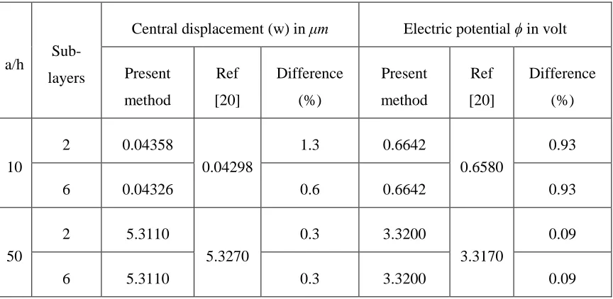
Table 2.1 Central displacement and electric potential, in sensor mode for the applied load of 1 KN/m2
a/h
Sub-layers
Central displacement (w) in μm Electric potential ϕ in volt
Present
method
Ref
[20]
Difference
(%)
Present
method
Ref
[20]
Difference
(%)
10
2 0.04358
0.04298
1.3 0.6642
0.6580
0.93
6 0.04326 0.6 0.6642 0.93
50
2 5.3110
5.3270
0.3 3.3200
3.3170
0.09
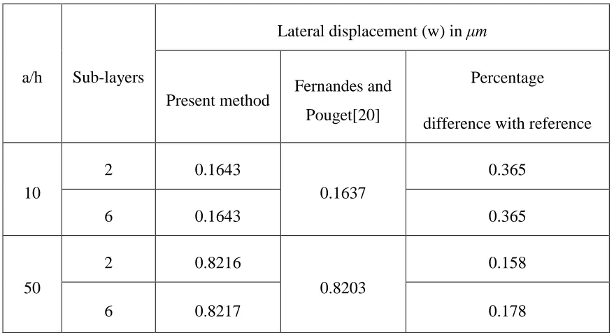
Table 2.2 Maximum lateral displacement, as an actuator for applied load of 50V
a/h Sub-layers
Lateral displacement (w) in μm
Present method Fernandes and Pouget[20]
Percentage
difference with reference
10
2 0.1643
0.1637
0.365
6 0.1643 0.365
50
2 0.8216
0.8203
0.158
6 0.8217 0.178
For the sensor mode, a closed circuit condition is created by grounding the top and bottom layers and applying a uniformly distributed load of 1KN/m2 on the top surface. Similarly, electrical potential of 50V is applied on the top and bottom faces across the thickness for the actuator mode. Since, the applied voltage at the top and bottom faces are equal and opposite, the plate bends the in direction of the axis of polarization. Analysis is performed using different aspect ratios and number of sub-layers on a model of 3×3 patches with each patch having 25 control points. The maximum central deflection (w) and the electric potential are calculated and presented in Tables 2.1 and 2.2 along with the results, from the work of Fernandes and Pouget [20]. An excellent agreement between the results is seen in these tables by considering only six layers.
2.4.2 Simply supported symmetric isotropic trapezoidal plates.
recorded in Table 2.3 for a/b =0.5, skew angle α=0 and a/b=1.0. Here ρ and D are the mass density and flexural rigidity respectively.
Table 2.3 Non-dimensional frequency
(b2/
2)
h/Dfor the simply supported
symmetric isotropic trapezoidal plate with a/h=50 and c/b=0.20.
Mode
a/b = 0.5 a/b = 1
Ref [26] Present Ref [26] Present
1 1.9376 1.9159 3.8242 3.8124
2 4.0555 4.0265 8.0707 8.0312
3 5.0874 5.0172 9.7898 9.7542
4 7.0252 6.9464 13.6640 13.5748
5 8.0199 7.9184 16.6810 16.5920
6 9.9950 9.8275 18.2350 18.1318
7 10.6940 10.5528 20.9340 20.7746
8 12.2630 11.9084 24.5670 24.3987
2.4.3 Cantilevered skewed sandwich trapezoidal plates.
After successfully verifying results from the present method with those from the literature, a skewed sandwich quadrilateral plate is examined. Let us consider a basic sandwich configuration consisting of a main supporting structure made of silicon between two thin ZnO layers polarized in the z direction. The layer thicknesses from the bottom to the top are 0.2h, 0.6h, and 0.2h where h represents the overall thickness of the sandwich plate. Other dimensions considered in this case are: a = 25mm, b = 12.5mm, 0 ≤ c ≤ 12.5mm and
50 ≤ (a/h) ≤ 100. Each piezoelectric layer is divided in to six sub-layers. The material
properties are obtained from the work of Polit and Bruant [29]. The static analysis is performed for both applied mechanical load and electrical load.
Fig. 2.2 shows the plot of the maximum deflection against c/b at the free end under an applied electric load of 100V. The skew angles considered are in the range of 0° ≤ α ≤ 45°. The base to tip ratio, c/b is varied in the range of 0.0≤c/b≤1.0, which covers plate geometry
from a triangle to parallelogram. The maximum deflection at c/b=0 decreases with increasing skew angle α, but is just the opposite at c/a=1. However, the deflection increases consistently with increasing c/b due to the fact that the surface area of the plate increases as long as a and b are kept the same. Also as the a/h ratio increases the plate becomes thinner and the displacements are higher, as inferred from Fig.2.2
Fig. 2.3 Maximum free end transverse displacement of a sandwich plate, for a uniformly distributed load of 50kN/m2 and α= 0°, 15°, 30° and 45°.
A uniformly distributed transverse load of 50 kN/m2 is applied on the top surface of the
displacements are provided in Fig. 2.3 and it shows a similar trend as seen in Fig. 2. 2 for the electrical load.
The free vibration analysis is performed for the cantilevered sandwich piezoelectric plate for various aspect ratios and skew angles. The electrical boundary conditions are set to zero on the top and bottom surface the of the plate. A 3×3 NURBS patch containing 36 control points in each patch is used in the analysis. The number of piezoelectric sub layers is kept at six. For the frequency analysis the forcing functions in the right hand side of the Eq. (2.16) is dropped resulting in a standard eigenvalue problem.
0 } { ] [ } { ]
[M Keq (2.17)
In which,
[
K
eq]
[
K
m]
[
K
me]
[
K
e]
1[
K
em]
As it can be inferred the plate stiffness is reduced because of the piezoelectric effect and thereby reducing the fundamental frequencies of the plate. The eigenvalues are obtained from Eq. (2.17), using matrix inverse iteration technique. Fig. 2.4(a–f) shows the changing
trend of the first five modes of the non-dimensional natural frequency
h
/C11 against(c/b). To investigate the influence of the taper ratio, the first five fundamental frequencies are analyzed in the range of 0 ≤ (c/b) ≤ 1 covering triangular to parallelogram plates. The
(a)
(c)
Fig. 2.4 First five non-dimensional natural frequencies of a cantilever sandwich plate with various skew angles and aspect ratios. In (a) and (b) the variation of natural frequencies are shown for a/h = 50 and in(c) and (d) the natural frequencies are given for a/h = 100.
Fig. 2.4a and 2.4b shows the variation of the first five non-dimensional natural frequency for a/h=50 and skew angle 0 ≤ α ≤ 45° at 15° interval. The taper ratio (c/b), is
varied in the range of 0 ≤ (c/b) ≤ 1. Similarly, Fig. 4c and 4d contain results for a/h = 100. Frequencies are seen to increase with the skew angle α and decrease with c/b for all the aspect ratios. Also seen particularly at higher modes is the tendency of the modal curves flipping from symmetric to asymmetric.
2.4.4 Cantilevered skewed sandwich trapezoidal plates: transient vibration
Transient response analysis of trapezoidal plate is carried out by Newmark’s direct
(a)
(c)
(e)
(g)
(i)