1Boosharaju Ravikumar,2 Dr. Y. R. Manjunath 1[email protected], 2[email protected]
ABSTRACT:The doubly-fed induction generator (DFIG) is widely used in variable speed wind energy conversion systems(WECS). This paper presents a review on various topologies, configuration, power converters and control schemes usedwith the operation of the DFIG. The main contribution of this work lies in thecontrol of GSC for supplying harmonics in addition toits slip power transfer. The rotor-side converter (RSC)is used for attaining maximum power extraction and tosupply required reactive power to DFIG. Wind energyconversion system (WECS) works as a staticcompensator (STATCOM) for supplying harmonicseven when the wind turbine is in shutdown condition.Control algorithms of both GSC and RSC arepresented in detail. Implemented project DFIG-basedWECS is simulated using MATLAB/Simulink. Aprototype of the proposed DFIG based WECS isdeveloped using a digital signal processor (DSP). Thewind energy is the preferred for all renewable energysources.
KEYWORDS-Variable speed DFIG, MPPT, windenergy, power quality, active filtering, GSC
I. INTRODUCTION
Now-a-days, the consumption of conventional energy sources has increased, So efforts have been made togenerate electricity from renewable energy sources such as wind, solar etc., Wind energy has become one of themost important and promising sources of renewable energy. This demands additional transmission capacity andbetter means of maintaining system reliability. Today the wind power capacity of the world is approximately50GW and it is expected to reach 160GW by 2012. In modern Wind Turbine Generation System (WTGS), thewind turbines are subjected to variation of load and impact of sudden wind speed variations.With increased penetration of wind power into electrical grids, Doubly-Fed Induction Generator (DFIG) windturbines are largely deployed due to their variable speed feature and hence influencing system dynamics. This hascreated an interest in developing suitable models for DFIG to
be integrated into power system studies. Thecontinuous trend of having high penetration of wind power, in recent years, has made it necessary to introducenew practices. Additionally, in order to model power electronic converters, in the simplest scenario, it is assumedthat the converters are ideal and the DC-link voltage between the converters is constant. Consequently, dependingon the converter control, a controllable voltage (current) source can be implemented to represent the operation ofthe rotor-side of the converter in the model.
In the literature, ManasiPattnaik, “Study of Doubly-Fed Induction Generator for variable Speed WindEnergy Conversion Systems”, gives brief idea about the operation and working of DFIG.[1].F. Poitiers, M.Machmoum,R. Le Doeuff and M.E. Zaim, “Control Of A Doubly-Fed Induction Generator For Wind EnergyConversion System”, gives information about the modeling of the DFIG and the control operation used.[2].R.Pena, J.C Clare and G.M Asher (1996), “Doubly Fed Induction Generator using back-to-back PWM converter andits application to variable-speed wind-energy generation”, describes the rotor side converter control of DFIGwhich provides the reference waveform for rotor side converter and the pulses for RSC have been obtained withthis the real and reactive power can be controlled.[3].
T.Thiringer, A.Petersson, and T.Petru (2003), “GridDisturbance Response Of Wind Turbine Equipped With Induction Generator and Doubly-Fed InductionGenerator”, gives brief idea about the grid disturbance response to fixed speed wind turbines
and wind turbineswith DFIG are
presented.[4].A.Petersson, L.Harnefors, and T.Thiringer (2005), “Evaluation OF Current ControlMethods For Wind Turbines Using Doubly-Fed Induction Machine,” gives brief idea about the analysis of thestator-flux oriented current control of
the DFIG.[5].CarlesBatlle,ArnauD`oria-Cerezo ,Romeo Ortega (2006) , “ARobustly Stable PI Controller for The Doubly-Fed Induction Machine”, this paper gives the brief idea about theclosed loop of the system using the PI controller.
II. CONTROL STRA TEGY FOR UPFC
These DFIGs also provide good damping performancefor the weak grid. Independent control of active andreactive power is achieved by the decoupled vectorcontrol algorithm. This vector control of such systemis usually realized in synchronously rotating referenceframe oriented in either voltage axis or flux axis. Inthis work, the control of rotor-side converter (RSC) isimplemented in voltage-oriented reference frame.Response of DFIG-based wind energy conversionsystem (WECS) to grid disturbance is compared to thefixed speed WECS. Generated power smoothening isachieved by implementing super magnetic energystorage systems.
The other auxiliary services such as reactive powerrequirement and transient stability limit are achievedby including static compensator
(STATCOM).Adistribution STATCOM
(DSTATCOM) coupled withfly-wheel energy storage system is used at the windfarm for mitigating harmonics and frequencydisturbances. A super capacitor energy storage systemat the dc link of unified power quality conditioner(UPQC).improving power quality and reliability. Theharmonics compensation and reactive power controlare achieved with the help of existing RSC. Anindirect current control technique is simple and showsbetter performance for eliminating harmonics ascompared to direct current control.
W o rkin g p rin cip le:In this work, a new control algorithm for GSC isproposed for compensating harmonics produced bynonlinear loads using an indirect current control. RSCis used for controlling the reactive power of DFIG.The other main advantage of proposed DFIG is that itworks as an active filter even when the wind turbine isin shutdown condition. Therefore, it compensates loadreactive power and harmonics at wind turbine stallingcase. Both simulation and experimental
performancesof the proposed integrated active filter-based DFIG arepresented in this work. The dynamic performance ofthe proposed DFIG is also demonstrated for varyingwind speeds and changes in unbalanced nonlinearloads at point of common coupling (PCC).
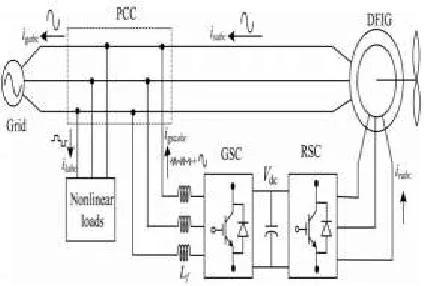
Fig. 1. Proposed system configuration
Above figure shows a schematic diagram of theproposed DFIGbased WECS with integrated activefilter capabilities. DFIG, the stator is directlyconnected to the grid as shown in Fig. 1. Two back-toback connected voltage source converters (VSCs) areplaced between the rotor and the grid. Nonlinear loadsare connected at PCC as shown in Fig. 1. Theproposed DFIG works as an active filter in addition tothe active power generation similar to normal DFIG.Harmonics generated by the nonlinear load connectedat the PCC distort the PCC voltage.
RSC is controlled for achieving maximum power pointtracking (MPPT) and also for making unity powerfactor at the stator side using voltage-orientedreference frame. Synchronous reference frame (SRF)
control method is used for extracting the fundamentalcomponent of load currents for the GSC control.
DESIGN OF DFIG-BA SED W ECS:
Selection of DC-Link Voltag e:The dc-link voltage of VSC must be greater than twicethe peak of maximum phase voltage. Whileconsidering from the rotor side, the rotor voltage is sliptimes the stator voltage. So, the design criteria for theselection of dc-link voltage can be achieved byconsidering only PCC voltage. While considering fromthe GSC side, the PCC line voltage (vab) is 230 V, asthe machine is connected in delta mode.Therefore, the dc-link voltage is estimated as
𝑉𝑑𝑐 ≥
√2 2
√3 ∗ 𝑚𝑉𝑎𝑏
where
Vab is the line voltage at the PCC.
Maximum modulation index is selected as 1for linear range.
The value of dc-link voltage (Vdc) by (1) isestimated as 375 V.
Hence, it is selected as 375 V
Selection of VSC Rating : The DFIG draws a lagging volt-ampere reactive(VAR) for its excitation to build the rated air gapvoltage. , the rating of the VSC used as RSC Srated isgiven as
𝑆𝑟𝑎𝑡𝑒𝑑= √𝑃𝑟 𝑚𝑎𝑥2 + 𝑄𝑟 𝑚𝑎𝑥2
Des ig n o f In terfacin g In d u cto r: The design of interfacing inductors between GSC andPCC depends upon allowable GSC current limit(igscpp), dc-link voltage, and switching frequency ofGSC. Maximum possible GSC line currents are usedfor the calculation. Maximum line current dependsupon the maximum power and the line voltage at GSC.The maximum possible power in the GSC is the slippower.Interfacing inductor between PCC and GSC isselected as 4 mH.
𝐿𝑖=
√3𝑚𝑣𝑑𝑐
12𝑎𝑓𝑚∆𝑖𝑔𝑠𝑐
= √3 × 1 × 375
12 × 1.5 × 10 000 × 0.25 × 3.76= 3.8𝑚𝐻
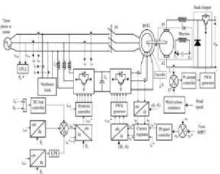
Fig. 2. Control algorithm of the proposed WECS.
CONTROL STRA TEGY:
Control algorithms for both GSC and RSC arepresented in this section. The control algorithm for emulating wind turbine characteristics using dcmachine and Type A chopper is also shown in Fig. 2.
Co n tro l o f RSC:The main purpose of RSC is to extract maximumpower with independent control of active and reactivepowers. Here, the RSC is controlled in oltageoriented reference frame., the active andreactivepowers are controlled by controlling direct andquadrature axis rotor currents (idr and iqr).
Where:
The speed error (ωer) is obtained by subtractingsensed speed (ωr) from the reference speed (ω∗r ).
kpd and kid are the proportional and integralconstants of the speed controller.
ωer(k) and ωer(k − 1) are the speed errors at kth and (k−1)th instants.
i * dr(k) and i * dr(k − 1) are the direct axis rotor reference current at kth and (k−1)th instants. Reference rotor speed (ω∗r ).
(i∗qr) is selected such that the stator reactive power (Qs) is made zero. In this DFIG, quadrature axisreference rotor current (i ∗qr) is selected for injecting
the required reactive power. Inner current controlloops are taken for control of actual direct andquadrature axis rotor currents (idr and iqr) close to thedirect and quadrature axis reference rotor currents (i∗dr and i ∗qr). The rotor currents idr and iqr arecalculated from the sensed rotor currents (ira, irb, and
irc).
Control of GSC:
The novelty of this work lies in the control of this GSCfor mitigating the harmonics produced by the nonlinearloads. The control block diagram of GSC is shown inFig. 2. Here, an indirect current control is applied onthe grid currents for making them sinusoidal andbalanced. Therefore, this GSC supplies the harmonicsfor making grid currents sinusoidal and balanced.These grid currents are calculated by subtracting theload currents from the summation of stator currentsand GSC currents. Active power component of GSCcurrent is obtained by processing the dc-link voltageerror (vdce) between reference and estimated dc-linkvoltage (V ∗ dc and Vdc) through PI controller as
Where kpdc and kidc are proportional and integral gains of dc-link voltage controller.Vdce(k) and Vdce(k− 1) are dclink voltage errors at kth and (k−1)thinstants. i∗gsc(k) and i ∗gsc(k − 1) are active powercomponent of GSC current at kth and (k−1)th instants.
III. SIM ULA TION RESULTS
The DFIG machine modes of operation namely sub-synchronous generating, super-synchronous generating aresimulated and the waveforms for speed and stator, rotor power and torque in each of the above modes of operationare presented. The rotor
speed is controlled by using v/f control and grid-side reactive power &Vdc are controlledby using voltage oriented control techniques. The grid-side current is controlled by using reference current controltechniques under p-q theory.
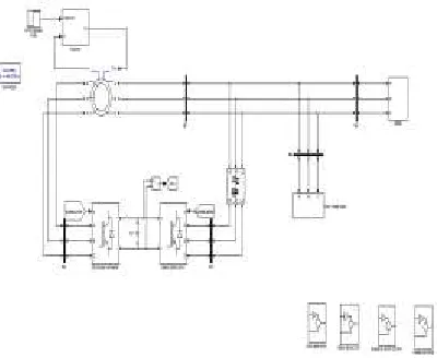
Fig 3 Matlab/simulinkdiagram of DFIG connected to WECS
(a)
(b)
Fig 5 (a)Load current (Iabc1) (b) Load voltage (Vabc1)
(a)
(b)
Fig 6 (a)grid current(Iabc) (b) grid voltage(Vabc)
Fig 7 stator current (Iabc stator)
(a)
(c)
Fig 8 (a) stator active power(b)grid active power (c)load activer in kw
(a)
(b)
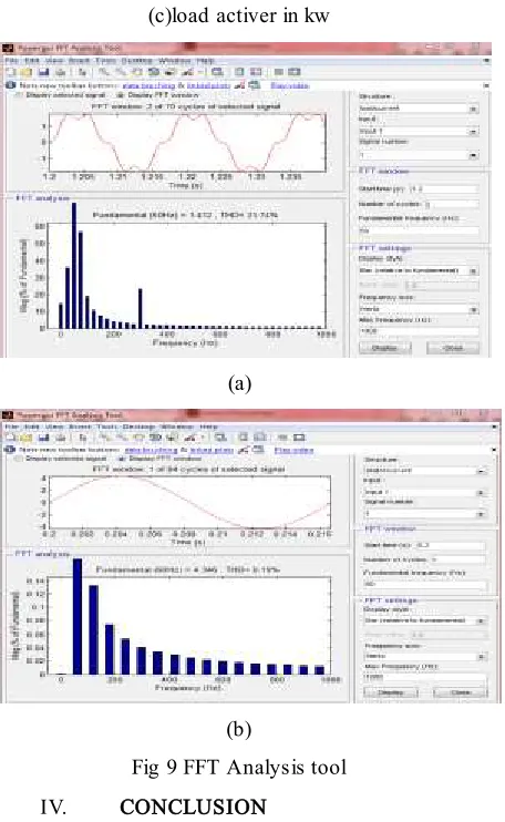
Fig 9 FFT Analysis tool
IV. CONCLUSION
Proposed DFIG, thereactive power for the induction machine has beensupplied from the RSC and the load reactive power hasbeen supplied from the GSC. Decoupled control ofboth active and reactive powers has achieved by RSCcontrol. DFIG has also been verified at wind turbinestalling condition for
compensating harmonics andreactive power of local loads. Proposed DFIG-basedWECS with an integrated active filter has beensimulated using MATLAB/Simulink environment, andthe simulated results are verified with test results of thedeveloped prototype of this WECS.
REFERENCES
1]. ManasiPattnaik, “Study Of Doubly Fed Induction Generator For Variable Speed Wind Energy Conversion Systems”, Special Issue OfInternational Journal Of Power System Operation and Energy Management, ISSN (PRINT):2231–4407,Vol – 1,Issue – 3.
[2]. F. Poitiers, M. Machmoum, R. Le Doeuff and M.E. Zaim, “Control Of A Doubly-Fed Induction
Generator For Wind Energy
ConversionSystem”,GE44-LARGE
,Ecoleploytechnique de l`universite`de Nantes, Saint Nazaire, France.
[3]. R. Pena, J.C Clare and G.M Asher, “Doubly Fed Induction Generator Using Back -to-Back PWM Converter and Its Application ToVariable-Speed Wind Energy Generation”, IEEE Proceeding Electrical Power Application., Vol.143, NO.3, May1996, ISSN.,PP. 231-241.
[4]. T. Thiringer, A. Petersson, and T. Petru ,“Grid Disturbance Response Of Wind Turbine Equipped With Induction Generator and DoublyFed Induction Generator”, in Proceeding IEEE Power Engineering Society General Meeting, Vol.3, Toronto, Canada, July 2003,pp.1542-47.
[5]. A. Petersson, L. Harnefors, and T.Thiringer, “Evaluation Of Current Control Methods For Wind Turbines Using Doubly-Fed InductionMachine”, IEEE Transaction on Power Electrnoics.,Vol 20,No.1,Jan 2005,PP.227-235, July 2000.
[7] H. Polinder, F. F. A. van der Pijl, G. J. de Vilder,and P. J. Tavner, “Comparison of direct-drive andgeared generator concepts for wind turbines,” IEEETrans. Energy Convers., vol. 21, no. 3, pp. 725– 733,Sep. 2006.
[8] R. Datta and V. T. Ranganathan, “Variable-speedwind power generation using doubly fed wound rotorinduction machine—A comparison with alternativeschemes,” IEEE Trans. Energy Convers., vol. 17, no.3, pp. 414–421, Sep. 2002.