ISSN (Print) : 2320 – 3765 ISSN (Online): 2278 – 8875
I
nternational
J
ournal of
A
dvanced
R
esearch in
E
lectrical,
E
lectronics and
I
nstrumentation
E
ngineering
(An ISO 3297: 2007 Certified Organization)
Vol. 4, Issue 3, March 2015
Conversion of Single Image into 3D Depth
Image using NI-LabVIEW
K. Mohamed Hussain
1, R. AllwynRajendran Zepherin
2, M. Shantha Kumar
3, S. Abirami
4UG Student, Dept of Instrumentation and Control Engineering, Saranathan College of Engineering, Trichy, India1 UG Student, Dept of Instrumentation and Control Engineering, Saranathan College of Engineering, Trichy, India 2 UG Student, Dept of Instrumentation and Control Engineering, Saranathan College of Engineering, Trichy, India 3 Asst.Professor, Dept of Instrumentation and Control Engineering, Saranathan College of Engineering, Trichy, India 4
ABSTRACT:This paper is merely deals with estimating the 3-Dimensional view of a single image and also
determining and altering various aspects of an image such as its alpha, beta, direction, border, background using NI -LabVIEW software. It can also be accomplished for reducing the size of the image as well as varying the maximum height of the image. The image to be used for conversion can be either acquired through camera using NI-Vision and Motion tool or we can load already acquired image. With Personal Computer installed with LabVIEW 2014, we can able to establish 3-Dimensional View and its corresponding depth of the acquired image.
KEYWORDS: NI-LabVIEW, 3Dimensional View, NI-Vision and Motion tool, PC.
I.INTRODUCTION
NI-LabVIEW is a program design language which allows meek interfacing with various hardware devices[2]. With its individual graphical programming environment, documents wrapping facts of thousands of devices and convenient toolkits, tracking down data using LabVIEW is much informal. LabVIEW was created by Jeff Kodosky 25years ago, he was also known as the “Father of LabVIEW” .First it was released for the Apple Macintosh in 1986, the graphical language at the core of LabVIEW is named "G"[4]. The hint at that period was to reform the measurement and automation industry, and the technology brought about the computer-generated instrument - serving engineers and experts to modify measurement schemes to fulfil their needs[7].
Till 1992 that LabVIEW was accessible for platforms other than the Macintosh and later it has experienced several revisions.NI-LabVIEW has several numbers of Functional Blocks which perform various programming tasks graphically. It uses Graphical Controls and Indicators and produces Real time flow of processes and programs virtually[1]. The interfacing measuring instruments such as sensors, transducers, meters etc. do not need any complex installation procedures, but needs devices like NI-DAQ, NI-ELVIS, NI-MYRIO etc. Programs in LabVIEW are called Virtual Instruments.
LabVIEW ties the design of user interfaces (called front panels) into the development cycle. LabVIEW programs/subroutines are called virtual instruments (VI). The structures and functions are found on the Functions palette and can be placed on the back panel. Collectively controls, indicators, structures and functions will be referred to as nodes. Nodes are connected to one another using wires – e.g. two controls and an indicator can be wired to the addition function so that the indicator displays the sum of the two controls. Thus a virtual instrument can either be run as a program, with the front panel serving as a user interface, or, when dropped as a node onto the block diagram, the front panel defines the inputs and outputs for the given node through the connector pane. This implies each VI can be easily tested before being embedded as a subroutine into a larger program.
ISSN (Print) : 2320 – 3765 ISSN (Online): 2278 – 8875
I
nternational
J
ournal of
A
dvanced
R
esearch in
E
lectrical,
E
lectronics and
I
nstrumentation
E
ngineering
(An ISO 3297: 2007 Certified Organization)
Vol. 4, Issue 3, March 2015
which permit the automatic reconstruction of 3D objects. Those techniques can be subdivided into two kinds of methods, active and passive. The drawback of the active methods is that the reconstruction process can turn out to be a high budget project. Therefore, the existing approach fits to the passive methods which necessitates less equipment and can be applied more generally.
With the progress of 3D applications, the conversion of existing 2D images to 3D images becomes a significant module of 3D content production. The conversion process of existing 2D images to 3D is commercially feasible and is satisfying the development of high quality stereoscopic images. The foremost method for such content conversion is to extend a depth map for each frame of 2D material. When observing the world, the human brain usually integrates the heuristic depth cues for the generation of the depth perception. The major depth perceptions to be distinguished are binocular depth cues from two eyes and monocular depth cues from a single eye[6]. The disparity of binocular visual system helps human eyes to converge and also to hold the object at the right distance. Monocular cues which include focus/defocus, motion parallax, relative height/size, and texture gradient offer various depth perceptions based on human experience. Therefore, humans are able to perceive depth from the single-view image/video.
II.LITERATURE SURVEY
3D imaging technology has come a long way from its roots in academic research labs, and thanks to innovations in sensors, lighting and most importantly, embedded processing, 3D vision is now appearing in a variety of machine automation applications. From vision-guided robotic bin-picking to high precision metrology, the latest generation of processors can now handle the immense data sets and sophisticated algorithms required to extract depth information and quickly make decisions. The LabVIEW Vision Development Module makes 3D vision accessible to engineers through seamless integration of software and hardware tools for 3D within one graphical development environment.
II.HARDWARE APPARATUS
The Hardware equipment required for this system is: 1. Camera.
2. Laptop with LabVIEW 2014 installed in it.
A. LAPTOP:
A DESKTOP or LAPTOP can be employed as a Personal Computer and additionally it must have LabVIEW 2014 Software installed in it. This is because LabVIEW 2014 Software version would have Vision and Motion Toolkit which is required for determining various aspects of an Image such as 3-Dimensional View, its depth (both Alpha & Beta values),border and background.
Figure 1: PC with LabVIEW
B. WEB CAMERA:
ISSN (Print) : 2320 – 3765 ISSN (Online): 2278 – 8875
I
nternational
J
ournal of
A
dvanced
R
esearch in
E
lectrical,
E
lectronics and
I
nstrumentation
E
ngineering
(An ISO 3297: 2007 Certified Organization)
Vol. 4, Issue 3, March 2015
Figure 2: Web Camera
II.LabVIEW DEPTH PROGRAMMING
As mentioned earlier, LabVIEW VI has three major components, they are: Front Panel, Block Diagram, Connector Panel. LabVIEW creates the user interface with the help of Front panel of the software. Front panel consists of Controls and Indicators. Block Diagram consists of Programming functions and Blocks (such as interfacing blocks, mathematical-trigonometrical functions, Digital Processing system interfaces).
A. BLOCK DIAGRAM:
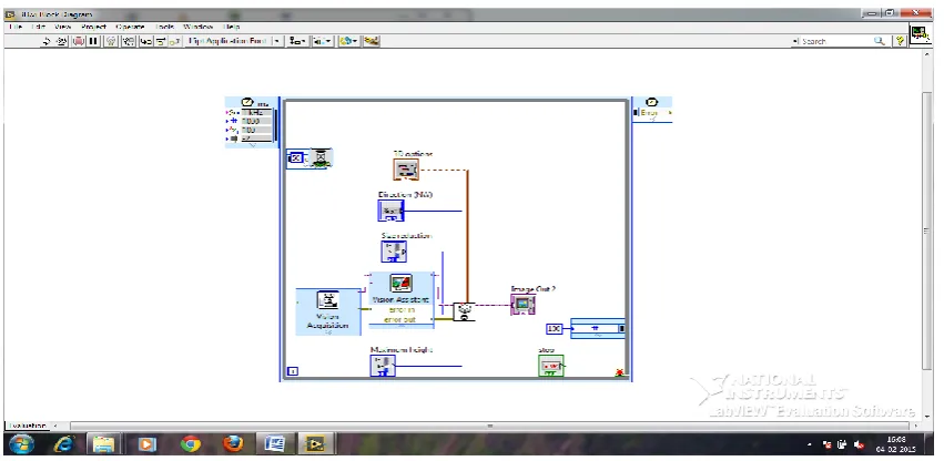
The block diagram contains the graphical source code uses graphical representations of functions to control the front panel objects. Front panel objects appear as icon terminals on the block diagram. Wires connect control and indicator terminals to Express VIs, VIs, and functions. Data flows through the wires in the following ways: from controls to VIs and functions, from VIs and functions to indicators, and from VIs and functions to other VIs and functions. The movement of data through the nodes on the block diagram determines the execution order of the VIs and functions. This movement of data is known as dataflow programming. The Block Diagram of the system is as shown in Figure 3.
Figure 3: Block Diagram of 3D Imaging VI
The Block Diagram consists of following blocks.
1) Vision Acquisition:
ISSN (Print) : 2320 – 3765 ISSN (Online): 2278 – 8875
I
nternational
J
ournal of
A
dvanced
R
esearch in
E
lectrical,
E
lectronics and
I
nstrumentation
E
ngineering
(An ISO 3297: 2007 Certified Organization)
Vol. 4, Issue 3, March 2015
2) Vision Assistant:
Vision Assistant Systems help to convert, filter and morph images. The process of converting the RBG Image (Left and Right) to Grayscale and extracting Red-Blue-Green Components are done through this block.
3) NI_Vision_Development_Module.lvlib: IMAQ 3D VIEW:
It displays an image in an isometric view. Each pixel from an image source is represented as a column of pixels in the 3D view. The pixel value corresponds to altitude. We need to create control for 3D options which consist of various properties such as alpha, beta, border, background, and plane. We also need to create separate controls for size reduction, maximum height and direction.
4) Timed While Loop:
Executes one or more sub diagrams, or frames, sequentially each iteration of the loop at the period you specify. Use the Timed Loop when you want to develop VIs with multi rate timing capabilities, precise timing, feedback on loop execution, timing characteristics that change dynamically, or several levels of execution priority. Right-click the structure border to add, deletes, insert, and merge frames. Set the time period of Timed While Loop to about 10 milliseconds.
B. FRONT PANEL:
The front panel is the user interfaces of a VI which can be built by using controls and indicators, which are the interactive input and output terminals of the VI, respectively. Controls and indicators are located on the Controls palette. Controls are knobs, push buttons, dials, and other input mechanisms. Controls simulate instrument input mechanisms and supply data to the block diagram of the VI. Indicators are graphs, LEDs, and other displays.
IV.RESULT
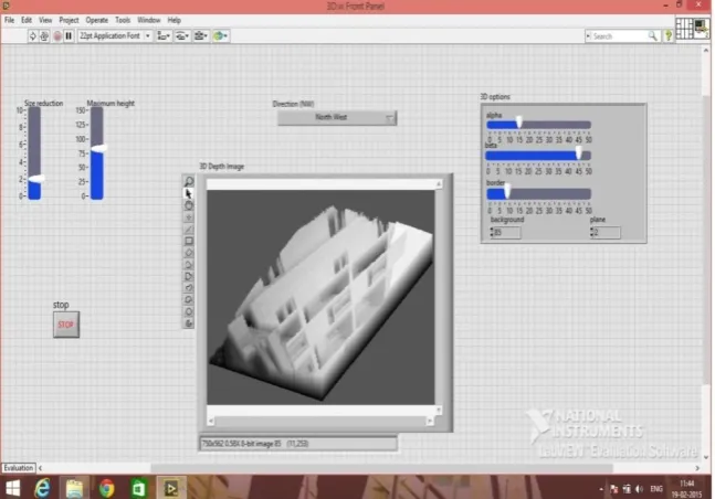
By varying the various aspects of 3D options, we can able to determine the depth of an image. When we change the values of Alpha and Beta properties, we could able to tilt the image both vertically and horizontally. The maximum limit of Alpha and Beta properties is 45 and its minimum limit is 15. We can also change its Border properties to estimate the border of the acquired image. Also, we can view the image in various directions such as North-West, South-West, South-East, and North-East. To view the image in Normal view, we need to select North-West direction in the Direction properties. We can also change the values of Maximum Height and Size Reduction to determine its maximum height and to reduce the size of the Acquired image.The Result that is displayed in the Front Panel of the System is as shown in Figure 4.
ISSN (Print) : 2320 – 3765 ISSN (Online): 2278 – 8875
I
nternational
J
ournal of
A
dvanced
R
esearch in
E
lectrical,
E
lectronics and
I
nstrumentation
E
ngineering
(An ISO 3297: 2007 Certified Organization)
Vol. 4, Issue 3, March 2015
V.CONCLUSION
Thus the 3-Dimensional view of a single image and various aspects of an image such as its alpha, beta, direction, border, and backgroundhas been determined and altered using NI-LabVIEW software. Reducing the size of the image as well as varying the maximum height of the imagewas also beingaccomplished. The image to be used for conversion can be either acquired through camera using NI-Vision and Motion tool or we can load already acquired image. Thus, with the help of Personal Computer installed with LabVIEW 2014, we wereable to establish 3-Dimensional View and its corresponding depth of the acquired image.
REFERENCES
[1]. Mohamed Hussain K., “Anaglyph 3Dimensional Image Processing using NI-LabVIEW”, IJRST-(International Journal for Innovative Research in Science and Technology), Volume-1, Issue-8, January 2015, ISSN: 2349-6010.
[2]. http://en.wikipedia.org/wiki/LabVIEW. [3]. http://www.ni.com/pdf/manuals...
[4]. Henry George Liddell, Robert Scott, “A Greek-English Lexicon”, on Perseus Digital Library. [5]. Roll Mann, Wilhelm, "ZweineuestereoskopischeMethoden", Annalen der Physik166: 186–187,1853 [6]. http://www.ni.com/video/2416/ The History of LabVIEW.