ISSN (Print) : 2320 – 3765
ISSN (Online): 2278 – 8875
I
nternational
J
ournal of
A
dvanced
R
esearch in
E
lectrical,
E
lectronics and
I
nstrumentation
E
ngineering
(A High Impact Factor, Monthly, Peer Reviewed Journal)
Website: www.ijareeie.com
Vol. 8, Issue 3, March 2019
Power Quality Improvement by Using UPQC
in Wind Energy Conversion System
Bhupendra Singh Niranjan 1, Dashrath Kumar 2
PG Student [Power System], Dept. of EEE, Maharishi University of Information Technology, Lucknow, U.P., India1
Asst. Professor, Dept. of EEE, Maharishi University of Information Technology, Lucknow, U.P., India2
ABSTRACT: Power quality has become a crucial factor today due to wide application of power electronics based equipment Day by day in industries and in distribution area power electronics based device are widely used and creates more power quality problems. The quality of the power is defective by certain reasons. This improvement of the quality of the power is seen e.g. as sag, swell, over voltages, under voltage, and harmonics Conventional equipment for enhancement of power quality is becoming inadequate. Unified power quality conditioner (UPQC) is one modern device which deals with voltage and current imperfections simultaneously. the unified power quality conditioner (UPQC), which consists of the parallel active power filter (PAPF) and the series active power filter (SAPF). The UPQC is a power conditioning device able to compensate all kinds of power quality faults. UPQC is also used to filter both current and voltage harmonics and to compensate the voltage sag. UPQC has the capability of improving power quality at the point of installation on power distribution systems or industrial power systems. This work deals with a way to improve the voltage compensation performance of the series APF. This improvement is achieved by improving the conventional hysteresis control system.
KEYWORDS: Power quality, UPQC,
I. INTRODUCTION
Wide application of power electronic based equipment has resulted in a serious impact on the nature of electric power supply. Smooth uninterrupted sinusoidal voltage at desired magnitude and frequency should always be provided to the consumers. On the other hand consumers should draw sinusoidal current [1]. Efforts are being made by many researchers for the effective improvement of power quality. UPQC is considered as the most powerful solution to the problems arising due to power quality. It is adequate enough to take care of supply voltage disturbances like voltage sag/swells, voltage flickers, load reactive power as well as voltage and current harmonics. The UPQC can also be named as the universal active power line conditioner, universal power quality conditioning system and also universal active filter. It is a cascade connection of series and shunt active power filter (APF) connected through a common DC link capacitor [2]. Poor power quality affects electricity consumers in many ways. The poor power quality may result into loss of production, damage of equipment or appliances, increased power losses, interference with communication lines etc. The decline quality of electric power is mainly because of current and voltage harmonics due to wide range application of static power electronics converters, zero and negative sequence component originated by the use of single phase and unbalanced load, reactive power, voltage sag, voltage swell, flicker, voltage interruption etc. Therefore, it is very crucial to maintain a standard power quality. The series APF is coupled to the supply line through a series transformer. The series APF prevents the source side voltage disturbances from entering into the load side to make the load voltage at desired magnitude and frequency [2]. Whereas the shunt APF connected in parallel across the load confines the current related problems to the load side to make the current from the source purely sinusoidal [3].
II. POWER QUALITY ISSUES AND ITS EFFECTS IN WIND ENERGY SYSTEM
ISSN (Print) : 2320 – 3765
ISSN (Online): 2278 – 8875
I
nternational
J
ournal of
A
dvanced
R
esearch in
E
lectrical,
E
lectronics and
I
nstrumentation
E
ngineering
(A High Impact Factor, Monthly, Peer Reviewed Journal)
Website: www.ijareeie.com
Vol. 8, Issue 3, March 2019
for measuring the power quality characteristics of a wind turbine [4]. For grid connection, the base for the analysis is provided by the data sheet with electrical characteristic of wind turbine.
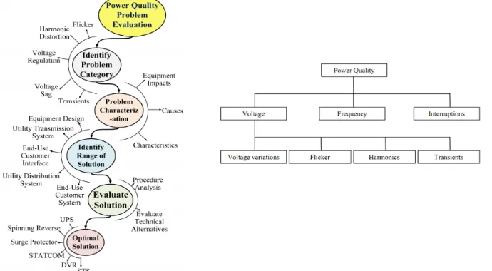
Perfect power quality means that the voltage is continuous and sinusoidal having a constant amplitude and frequency. Power quality can be expressed in terms of physical characteristics and properties of electricity. It is most often described in terms of voltage, frequency and interruptions. The quality of the voltage must fulfill requirements stipulated in national and international standards. In these standards, voltage disturbances are subdivided into voltage variations, flicker, transients and harmonic distortion [5]. Fig. 1 shows a classification of different power quality phenomena.
Fig. 1(a): Flow diagram for evaluation of power quality problems,solution of a problem comes through a process starting with identification of the problem category.
Fig. 1(b): Classification of different power quality phenomena
2.1. POWER QUALITY ISSUES
A. VOLTAGE VARIATION
The voltage variation mainly results from the wind velocity and generator torque. The voltage variation is directly related to real and reactive power variations. The wind generating system equipped with an asynchronous generator consumes the reactive power and can cause additional negative problem for the grid. Switching the wind turbine generator ON and OFF also varies the voltages. The voltage variation is commonly classified as short duration and long duration voltage variation.
Various types of voltage variations are given as follows:
Voltage sag. Voltage flicker.
Short interruptions Voltage swells.
B. FLICKER
ISSN (Print) : 2320 – 3765
ISSN (Online): 2278 – 8875
I
nternational
J
ournal of
A
dvanced
R
esearch in
E
lectrical,
E
lectronics and
I
nstrumentation
E
ngineering
(A High Impact Factor, Monthly, Peer Reviewed Journal)
Website: www.ijareeie.com
Vol. 8, Issue 3, March 2019
network situation and independent of short circuit apparent power of the grid. It gives ratio of short circuit power and generated rated apparent power, which is necessary to achieve a long term flicker level. (Plt), as the given equation.
ψ , =
Where, C(ψk, Va)-flicker coefficient depends on grid impedance angle ψk and the average wind velocity Va.
Sk - Short-circuit power of grid at point of common coupling. , Sn- Apparent power of wind turbine at rated power.
Plt- Long term flicker emission.
The flicker standards are generally used to characterize the transient voltage variations. The short flicker is evaluated over a 10 min period and long term flicker is evaluated over 2 hours period.
Causes— Fluctuation of active and reactive power of wind turbine, i.e. yaw error, wind shear, wind turbulence or fluctuation in control system, switching operations in wind turbine. In fixed speed wind turbine each time a rotor blade passes through the tower, the power output of the turbine reduces. This effect cause's periodical power fluctuation with a frequency of about 1 Hz, where as in variable speed turbine power fluctuation are smoothed. Flickers are produced by arc furnace, arc lamps, capacitor switching.
Consequences—Degradation of power quality, damage to sensitive equipments.
C. HARMONICS
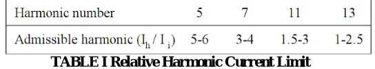
It results from the operation of power electronic converters. The harmonic voltage and current should be limited to the acceptable level at the point of wind turbine connection to the network. The emission of harmonic current during the continuous operation of wind turbine with power converter has to be stated. The relative harmonic current limit is stated in the Table I.
TABLE I Relative Harmonic Current Limit
Where Ih is the total harmonic current of hth order caused by the consumer and I is the rms current corresponding to the
consumer agreed power.
D. WIND TURBINE LOCATION IN THE POWER SYSTEM
The way of connecting the wind generating system into the power system highly influences the power quality. As a rule, the impact on power quality at the consumer’s terminal is located close to the load is higher, than connected far away from the load. When the wind generating system is connected to a medium voltage transmission line, the distance between the wind generating station and point of common coupling is small, such system are economical as compared to other location. Thus the operation and its influence on power system depends on the structure of the adjoining power network.
E. SELF EXCITATION OF WIND TURBINE GENERATINGSYSTEM
The self-excitation of wind turbine generating system (WTGS) with an asynchronous generator takes place after disconnection of WTGS with local load. The risk of self-excitation arises especially when WTGS is equipped with compensating capacitor. The capacitor connected to induction generator provides reactive power compensation. However, the voltage and frequency are determined by the balancing of the system. The disadvantages of self-excitation are the safety aspect and balance between real and reactive power.[6]-[8]
Causes—If the sensitive equipment is connected to the generator during the self-excitation, the equipment may be a
ISSN (Print) : 2320 – 3765
ISSN (Online): 2278 – 8875
I
nternational
J
ournal of
A
dvanced
R
esearch in
E
lectrical,
E
lectronics and
I
nstrumentation
E
ngineering
(A High Impact Factor, Monthly, Peer Reviewed Journal)
Website: www.ijareeie.com
Vol. 8, Issue 3, March 2019
III. UNIFIED POWER QUALITY CONDITIONER (UPQC)
The best protection for sensitive loads from sources with inadequate quality, is shunt-series connection i.e. unified power quality conditioner (UPQC) .Recent research efforts have been made towards utilizing unified power quality conditioner (UPQC) to solve almost all power quality problems for example voltage sag, voltage swell, voltage outage and over correction of power factor and unacceptable levels of harmonics in the current and voltage The basic configuration of UPQC is shown in Fig. 2 .[9]
Fig.2 Basic configuration of UPQC
The main purpose of a UPQC is to compensate for supply voltage flicker/imbalance, reactive power, negative sequence current, and harmonics . In other words, the UPQC has the capability of improving power quality at the point of installation on power distribution systems or industrial power systems. The UPQC, therefore, is expected as one of the most powerful solutions to large capacity sensitive loads to voltage flicker/imbalance. Unified Power Quality Conditioner (UPQC) for non-linear and a voltage sensitive load has following facilities:
It eliminates the harmonics in the supply current, thus improves utility current quality for nonlinear loads.
UPQC provides the VAR requirement of the load, so that the supply voltage and current are always in phase, therefore, no additional power factor correction equipment is necessary.
UPQC maintains load end voltage at the rated value even in the presence of supply voltage sag. The voltage injected by UPQC to maintain the load end voltage at the desired value is taken from the same dc link, thus no additional dc link voltage support is required for the series compensator.
The UPQC consists of two three phase inverters connected in cascade in such a manner that Inverter I is connected in series with the supply voltage through a transformer inverter II is connected in parallel with the load.
The main purpose of the shunt compensator is to compensate for the reactive power demanded by the load, to eliminate the harmonics and to regulate the common dc link voltage.
The series compensator is operated in PWM voltage controlled mode.
It injects voltage in quadrature advance to the supply voltage (current) such that the load end voltage is always maintained at the desired value. The two inverters operate in a coordinated manner.
IV. CONTROL ALGORITHM IN UPQC
ISSN (Print) : 2320 – 3765
ISSN (Online): 2278 – 8875
I
nternational
J
ournal of
A
dvanced
R
esearch in
E
lectrical,
E
lectronics and
I
nstrumentation
E
ngineering
(A High Impact Factor, Monthly, Peer Reviewed Journal)
Website: www.ijareeie.com
Vol. 8, Issue 3, March 2019
4.1 UNIT VECTOR TEMPLATE GNERATION
The control technique used here is Unit vector template generation technique In this case supply voltage is made distorted and Unit Vector Templates are extracted from it. The distorted input source voltage contains harmonic components in addition to the fundamental component. For extraction of these unit vectors, the supply voltage is first measured and the product of this and gain (1/ Vm) is done, Vm being the peak fundamental supply voltage. After this unit vector templates are generated by using a phase locked loop.
Va = Sinωt Vb = Sin (ωt-120)
Vc= Sin (ωt+120)
Figure 3 Generation of Unit Vector Templates and reference Load Voltages
Supply voltage is then multiplied with the unit vector templates and reference load voltage is generated. The reference load voltage generated is given by V*abc.
V*abc= Vm*Uabc
Then the comparison of actual load voltage and reference load voltage is done. Error is calculated and send into a hysteresis band for generating the gate pulse for the series inverter. Shunt Active Power Filter is used for current harmonics compensation. Generation of pulses for the shunt inverter DC link voltage is then measured an it its comparison is done with the reference dc link voltage. After that error is processed by utilizing a PI controller, and to produce the reference current these results are multiplied by unit vector templates. Comparison of reference and actual source current is done and a hysteresis band controller is used for processing the error and production of gate pulses for parallel inerter circuit is completed.[10-11]
4.2 SYNCHRONOUS REFERENCE FRAME AND P-Q CONTROL OF UPQC- 4.2.1-Control Method for Series Active Filter
ISSN (Print) : 2320 – 3765
ISSN (Online): 2278 – 8875
I
nternational
J
ournal of
A
dvanced
R
esearch in
E
lectrical,
E
lectronics and
I
nstrumentation
E
ngineering
(A High Impact Factor, Monthly, Peer Reviewed Journal)
Website: www.ijareeie.com
Vol. 8, Issue 3, March 2019
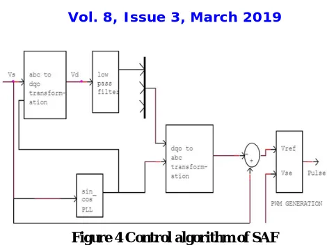
Figure 4 Control algorithm of SAF
Equation depicting transformation of supply voltage and load current into d-q-o coordinate are given below
Along with the fundamental component harmonics are also present in the d-axes voltage. A second order LPF is used for filtering out the harmonic components. Then the reference voltage Vref is then estimated by utilizing d-q-o to a-b-c transformation. Then the output of series active filter and the reference voltage generated is fed to a hysteresis band controller to generate the gate pulses
4.2.2-Control Method Employed for Shunt Active Filter-
For calculating the reference current in this method P-Q methodology has been utilized. Clarke’s transformation given in equation (1),(2),(3) and (4) are used for transformation of reference voltages generated at SAF and load current in to
α-β-0 coordinates
Equation (5) is used for the calculation of real power and imaginary power in the Source side. These are instantaneous power-
ISSN (Print) : 2320 – 3765
ISSN (Online): 2278 – 8875
I
nternational
J
ournal of
A
dvanced
R
esearch in
E
lectrical,
E
lectronics and
I
nstrumentation
E
ngineering
(A High Impact Factor, Monthly, Peer Reviewed Journal)
Website: www.ijareeie.com
Vol. 8, Issue 3, March 2019
Figure 5 Control algorithm of PAF
Due to the absence of unbalance the power Po is zero. Comparison of measured and reference DC-link voltage is done and a Proportional integral controller is used for processing the error produced. The main reason behind using this controller is that it helps in reducing the steady state error to a zero value. PI controller’s yield is termed as Ploss. Then the reference source current is converted to a-b-c frame of reference using the Eq.(7)-
Finally the comparison of these current and actual source current is done by the help of a hysteresis band controller and gate pulses for the shunt Active power filter are generated [12]
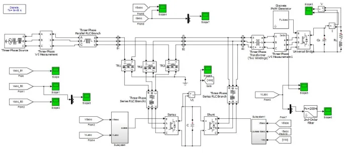
V. SIMULATION RESULTS
Figure 6 Simulink Model
ISSN (Print) : 2320 – 3765
ISSN (Online): 2278 – 8875
I
nternational
J
ournal of
A
dvanced
R
esearch in
E
lectrical,
E
lectronics and
I
nstrumentation
E
ngineering
(A High Impact Factor, Monthly, Peer Reviewed Journal)
Website: www.ijareeie.com
Vol. 8, Issue 3, March 2019
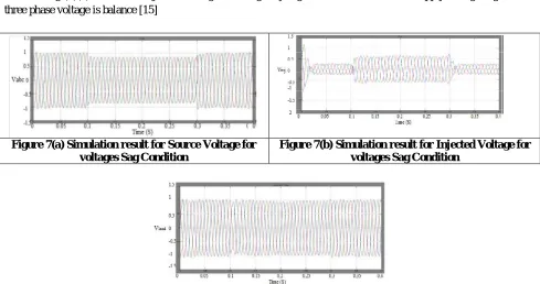
A. 20% sag compensation:- The UPQC model 20% voltage sag crated in 0.1s to 0.3s in three phase voltage as shown in fig(7)(a). When the three phase supply voltage sag is produce at 0.1s to 0.3s the series APF are activated and inject the lost sag voltage fig (7)(b). The load voltage side to maintain the magnitude constant during voltage sag condition as shown in fig (7)(c). The series injection voltage is during only sag condition than clear the supply voltage sag and the three phase voltage is balance [15]
B.
Figure 7(a) Simulation result for Source Voltage for voltages Sag Condition
Figure 7(b) Simulation result for Injected Voltage for voltages Sag Condition
Figure 7(c) Simulation result for Load Voltage for voltages Sag Condition
B. 20% swell compensation:-
In this simulation 20% voltage swell are created in three phase at 0.1s to 0.3s as shown in fig (8) (a). When voltage swell are produced in 0.1s to 0.3s the series APF is activated and inject the missing voltage as shown in fig (8)(b)[10]. The series APF operation and injection voltage is out of phase with supply voltage swell condition. After the swell will be cleared the load voltage waveform will balanced fig (8)(c)
Figure 8(a) Simulation result for Source Voltage for voltages Swell Condition
ISSN (Print) : 2320 – 3765
ISSN (Online): 2278 – 8875
I
nternational
J
ournal of
A
dvanced
R
esearch in
E
lectrical,
E
lectronics and
I
nstrumentation
E
ngineering
(A High Impact Factor, Monthly, Peer Reviewed Journal)
Website: www.ijareeie.com
Vol. 8, Issue 3, March 2019
Figure 8(c) Simulation result for Load Voltage for voltages Swell Condition
VI. CONCLUSION
This paper describes a new control strategy used in the UPQC system, the proposed control strategy use only loads and mains voltage measurements for series APF based on the synchronous reference frame theory. The instantaneous reactive power theory is used for shunt APF control algorithm by measuring mains voltage and currents. The conventional methods require measurements of the load, source and filter voltages and currents. The simulation results show that the voltage sag, voltage swell, can be compensated very effectively using proposed control technique.
REFERENCES
[1] H. Awad, M. H.J Bollen, “Power Electronics for Power Quality Improvements,” IEEE Symp. on Industrial Electronics, 2003, vol.2 , pp.1129-1136.
[2] Aredes M., Heumann K., Watanabe E.H., “An universal active power line conditioner”, IEEE Transactions Power Delivery, 1998, vol. 13, pp. 545-551.
[3] Metin Kesler and Engin Ozdemir, “A Novel Control Method for Unified Power Quality Conditioner(UPQC ) Under Non-Ideal Mains Voltage and Unbalanced Load Conditions,” IEEE Conference on Applied Power Electronics, Feb. 2010, pp. 374-379.
[4] Wind Turbine Generating System-Part 21, International standard-IEC 61400-21, 2001.
[5] Larsson, A, "Flicker and Slow Voltage Variations from Wind Turbines", Proceedings of the 7th International Conference on Harmonics and Quality of Power (ICHQP '96), Las Vegas, U.S.A. October 1996, p. 270 - 275.
[6] R Blaabjerg, Z. Chen, S.B. Kjaer, "Power Electronics as efficient interface in dispersed power generation System." IEEE Trans. On Power Electron. Vol. 19, No. 5, pp. 1184¬1194., Sept. 2004
[7] Sung-Hun, Seong R. Lee, HoomanDehbonei, Chemmangot V. Nayar," Application of Voltage-and Current-Controlled Voltage Source Inverters for Distributed Generation System.," IEEE Trans. On Energy Conversion, Vol.21, No.3, pp. 782¬788, Sept. 2006.
[8] Juan Manel Carrasco, 'Power Electronic System for Grid Integration of Renewable Energy Source: A Survey', IEEE Trans on Industrial Electronics, Vol. 53, No. 4, pp. 1002¬1014, August 2006
[9] X. Zhang, W. Zhang, Y. Lv, W. Liu, and Q. Wang, “Unified power quality conditioner with model predictive control,” in Proc. 5th Int. Conf. Comput. Sci. Educ., Aug. 24–27, 2010, pp. 1239–1244.
[10] Yash Pal, A. Swarup, Bhim Singh, “A control strategy based on UTT and Icosɸ theory of threephase, four wire UPQC for power quality improvement ” International Journal of Engineering, Science and Technology Vol. 3, No. 1, 2011, pp. 30-40.
[11] S.Shankar, A.Kumar and W.Gao “Operation of Unified Power Quality Conditioner under Different Situation,” IEEE Proc. Power and Energy Society General Meeting, July 2011, pp.1-10.