Two Mode Deep Changes for Strong Power
Conversion in Heating System
N.VijayaSarathi1, C.Mohanapriya2
Assistant Professor, Dept. of EEE, Saranathan College of Engineering, Trichy, Tamilnadu, India 1,2
PG Student [PED], Dept. of EEE, Saranathan College of Engineering, Trichy, Tamilnadu, India 3
ABSTRACT:Two mode strong changes use the half bridge inverter in two operating modes to achieve efficiency in a wide power levels. By comparing with dual mode resonant converter the class D full bridge resonant inverter operates only in single mode where low range of power levels are not possible. The dual mode strong change can operate with Zero Voltage Switching and Zero Current Switching so the switching losses are minimised. Induction heating is the fast growing technology in domestic appliances it has high efficiency and faster heating times. In this paper dual mode deep change function has been used for heating system applications.
KEYWORDS: Induction heating (IH), Half bridge inverter, resonant converter.
I.INTRODUCTION
The main advantage of domestic induction heating is cleanliness, rapid heating, high power densities, accurate time and temperature control. IH is a non contact process. It uses high frequency electricity to heat materials that are electrically conductive. When the pot is directly heated by the induced currents generated within a varying magnetic field in the range of 20-100KHZ.The magnetic field is generated by a inductor coil system, supplied by a resonant converter. In Resonant converter higher output occurs at resonant frequency, yielding efficiency also high. The conventional series half bridge ZVS resonant inverter is using IH application.
In this converter the resonance frequency is higher than the switching frequency, yielding to the maximum efficiency at maximum output. Whereas if the switching frequency is higher than the resonant frequency. Thus with the increased switching frequency the losses are increased for lower power output range [2] [3].To overcome this limitation dual mode resonant converter is used. The main advantage of resonant converter is to improve the efficiency even at low output power range by reducing switching losses. Class-D half-bridge converter is used in the high output power range, whereas class-DE half-bridge converter [3], [4] is used in the low to medium output power range. The combination of these operation modes achieves high efficiency levels in a wider range of output power levels.
II.HALF BRIDGE RESONANT CONVERTER
The conventional method used half bridge series resonant converter. It is one switch topology method for medium-high output power levels due to its high efficiency and low voltage stress across the switching devices. In Half bridge resonant converter consist of passive resistance and inductance. The series resonant half bridge applied to induction heating operates at switching frequency higher than the resonant frequency to achieve soft switching conditions. To reduce switching losses a snubber capacitor is added.
In class D operation mode implies the snubber capacitor Cs is much lower than the resonant capacitor Cr .In class-DE
III.TWO MODE DEEP CHANGER
Fig.1. Two mode strong converter
The dual mode resonant converter can be used in order to improve efficiency in whole operating range. In dual mode resonant converter electromechanical switches SPST 1 and SPST 2 allow varying the snubber and resonant capacitance in order to change the operation mode. They are six operation modes for the converter.
MODE I:
Fig.2. High side transistor are turned on
In mode I when high side transistor is turned on low side transistor are turned off the load current is positive and it flows to the load.
MODE II:
Fig .3.Transistors are off state
MODE III:
Fig. 4. Low side diode turns on
Both the side high and low side transistor are turned off.The load current is positive. It is supplied by the low-side diode. The power flows to the load.
MODE IV:
Fig .5. Low side transistor are turn on
When low side transistor are turned on.The load current becomes negative no power flows to the load.
MODE V:
Fig.6.Both capacitors are discharged condition
The low-side transistor is deactivated. The load current charges the low-side snubber capacitor to the supply voltage. The high-side snubber capacitor is discharged.
When both snubber capacitors are charged/discharged. The negative load current flows through the high-side diode.
IV. SIMULATION
The simulation is done in a step by step manner in MATLAB-Simulink R2010a.The simulation of entire Series Resonant Converter system with diode bridge rectifier, inductor, capacitor.
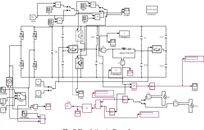
SIMULATION CIRCUIT IN D MODE:
Fig 8 Simulation in D mode
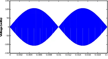
The results for the simulation of class D under varying Power, voltage and current are shown below
Fig.9. Output Voltage waveform
Fig.10.Output Current waveform
vs1 vs v+ -v4 v+ -v3 v + -v2 v + -v1 Co ntinuous
p o we rg ui
0 c
V T o Workspace2
I To Workspace1
Switch Step
Sine Wave1 Si ne Wave
Scope6 Scope2 Scope1 Scope >= >= >= >=
signa lrm s
sig na lrm s
signa lrm s
Product g 1 2 g 1 2
INDUC TOR POT
g m C E g m C E i+ -I1 [A] Goto [A] From PI DE2 DE1 1 DE Mode D1 0 D Mode D C s3 C s2 C r3 C r2 C r1 C r s -+ C b
0 0.002 0.004 0.006 0.008 0.01 0.012 0.014 0.016 0.018 0.02 -25 -20 -15 -10 -5 0 5 10 15 20 25 Time (Seconds) V o lt a g e ( v o lt s )
Fig.11.Output Power waveform
SIMULATION CIRCUIT IN DE MODE:
Fig 10 Simulation circuit in DE mode Fig .12.Simulation circuit in DE mode
The results for the simulation of class DE under varying Power, voltage and current are shown below
Output waveforms in DE mode
Fig.13.Output voltage waveform
vs1 vs v + -v4 v+ -v3 v + -v2 v + -v1
Co ntinu ou s
p owe rg ui
0 c
I1 T o Workspace3
V T o Workspace2
T To Workspace1
Switch Step
Sine Wave 1 Sine Wave
Scope6 Scope2 Scope1 Scop e >= >= >= >=
sign alrm s
sig na lrms
sign alrm s
Product g
1 2
g
1 2
IND UC TOR POT
g m C E g m C E i + -I1 [A] Go to [A] From PI DE2 DE1 1 DE Mode 10 05 6 2.88 100 D1 0 D Mode
D C s3 C s2 C r3 C r2 C r1 C r s -+ C b
0 0.002 0.004 0.006 0.008 0.01 0.012 0.014 0.016 0.018 0.02 -150 -100 -50 0 50 100 150 V o lt a g e ( v o lt s )
0 0. 002 0.004 0. 006 0.008 0.01 0.012 0. 014 0.016 0. 018 0.02 0 50 100 150 200 250 300
Tim e (Se conds)
Fig.14. Output Current waveform
Fig.15. Output Power waveform
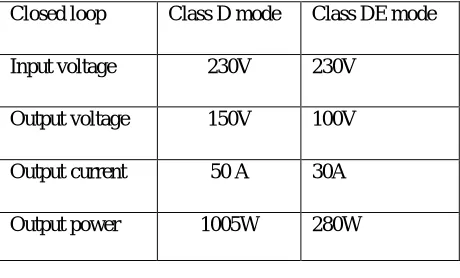
In Fig 10 and 15we get the Output Power, Voltage, Current .Comparison between D and DE mode are listed below.
Table I: Comparison in D and DE mode
V.CONCLUSION
Class-D half bridge converter is used in the high output power range, whereas class-DE half-bridge converter is used in the low to medium output power range. The combination of these operation modes achieves high efficiency levels in a wider range of output power levels. In the dual-mode resonant converter, class -D and class- DE operation modes are combined to optimize the efficiency in wide range of output power levels. Thus, the presented dual-mode resonant converter topology is a cost-effective implementation for domestic induction heating appliances.
REFERENCES
[1] Ahmed, N. A. (2011). High-frequency soft-switching ac conversion circuit with dual-mode PWM/PDM control strategy for high-power IH applications. Industrial Electronics, IEEE Transactions on, 58(4), 1440-1448.
[2] Burdio, J. M., Monterde, F., Garcia, J. R., Barragan, L. A., & Martinez, A. (2005). A two-output series-resonant inverter for induction-heating cooking appliances. Power Electronics, IEEE Transactions on, 20(4), 815-822.
Closed loop Class D mode Class DE mode
Input voltage 230V 230V
Output voltage 150V 100V
Output current 50 A 30A
Output power 1005W 280W
0 0.002 0.004 0.006 0.008 0.01 0.012 0.014 0.016 0.018 0.02 -30
-20 -10 0 10 20 30
C
u
rr
e
n
t
(A
m
p
s
)
0 0. 002 0.004 0. 006 0.008 0.01 0.012 0. 014 0.016 0. 018 0.02 0
50 100 150 200 250 300
P
o
w
e
r
(W
a
tt
s
[3] Dieckerhoff, S., Ruan, M. J., & De Doncker, R. W. (1999). Design of an IGBT-based LCL-resonant inverter for high-frequency induction heating. In Industry Applications Conference, 1999. Thirty-Fourth IAS Annual Meeting. Conference Record of the 1999 IEEE (Vol. 3, pp. 2039-2045). IEEE.
[4] Esteve, V., Sanchis-Kilders, E., Jordan, J., Dede, E. J., Cases, C., Maset, E., & Ferreres, A. (2011). Improving the efficiency of IGBT series-resonant inverters using pulse density modulation. Industrial Electronics, IEEE Transactions on, 58(3), 979-987.
[5] Fujita, H., Uchida, N., & Ozaki, K. (2011). A new zone-control induction heating system using multiple inverter units applicable under mutual magnetic coupling conditions. Power Electronics, IEEE Transactions on, 26(7), 2009-2017.
[6] Jung, Y. C. (1999). Dual half bridge series resonant inverter for induction heating appliance with two loads. Electronics letters, 35(16), 1345-1346.
[7] Kwon, Y. S., Yoo, S. B., & Hyun, D. S. (1999, March). Half-bridge series resonant inverter for induction heating applications with load-adaptive PFM control strategy. In Applied Power Electronics Conference and Exposition, 1999. APEC'99. Fourteenth Annual (Vol. 1, pp. 575-581). IEEE.
[8] Llorente, S., Monterde, F., Burdio, J. M., & Acero, J. (2002, March). A comparative study of resonant inverter topologies used in induction cookers. InAPEC. Seventeenth Annual IEEE Applied Power Electronics Conference and Exposition (Vol. 2, pp. 1168-1174).
[9] Lucia, O., Burdio, J. M., Barragan, L. A., Acero, J., & Millán, I. (2010). Series-resonant multiinverter for multiple induction heaters. Power Electronics, IEEE Transactions on, 25(11), 2860-2868.
[10] Millan, I., Puyal, D., Burdio, J. M., Bemal, C., & Acero, J. (2007, February). Improved performance of half-bridge series resonant inverter for induction heating with discontinuous mode control. In Applied Power Electronics Conference, APEC 2007-Twenty Second Annual IEEE (pp. 1293-1298). IEEE.
[11] Millan, I., Puyal, D., Burdio, J. M., Bemal, C., & Acero, J. (2007, February). Improved performance of half-bridge series resonant inverter for induction heating with discontinuous mode control. In Applied Power Electronics Conference, APEC 2007-Twenty Second Annual IEEE (pp. 1293-1298). IEEE.
[12] Nguyen-Quang, N., Stone, D. A., Bingham, C. M., & Foster, M. P. (2006, May). Single phase matrix converter for radio frequency induction heating. In Power Electronics, Electrical Drives, Automation and Motion, 2006. SPEEDAM 2006. International Symposium on (pp. 614-618). IEEE.
[13] Saha, B., Kwon, S. K., Ahmed, N. A., Omori, H., & Nakaoka, M. (2008). Commercial frequency AC to high frequency AC converter with boost-active clamp bridge single stage ZVS-PWM inverter. Power Electronics, IEEE Transactions on, 23(1), 412-419.
BIOGRAPHY