Soft Computing Application for Controlling
Three Phase Induction Motor
Nitin Goel1, Neha Saxena2
Assistant Professor, Dept. of Electrical Engg, YMCA University of Sci. and Tech., Faridabad, Haryana, India1 PG Student, Dept. of Electrical Engg, YMCA University of Sci. and Tech., Faridabad, Haryana, India2
ABSTRACT:This paper present the implementation of soft computing for controlling the parameters of the induction
motor. The large demand of induction motor in industries needs to have a wide band of operation of the motor such that it can operate for various tasks. One of the important characteristics of the motor is speed as desired task need desired speed and for this a need of controller to control the machine parameters. For the developments of the controller, various advanced control techniques are used, like Fuzzy Logic Control, Artificial Neural Network (ANN), Genetic Algorithm (GA) or the combination of them. In this paper, Fuzzy Logic Controller based vector control scheme is proposed for controlling induction motor parameters. Fuzzy Logic Controller operates on the rule base in which the output is obtained to control the parameters of the system. The proposed Fuzzy controller is designed in Matlab/Simulink framework and results are shown in term of various parameter characteristics curves.
KEYWORDS: Fuzzy Logic Controller, induction motor, MATLAB, soft computing.
I. INTRODUCTION
As the squirrel cage induction motors have an inherent advantage like simplicity, reliability, low cost & virtually maintenance use for high-performance industrial applications. The control of squirrel cage induction motor is remaining a challenging problem as non-linearity and rotor parameters vary with the operating condition. For controlling of squirrel cage induction motor various controllers have been developed like scalar, vector, PI controller [3] etc.
A scalar controller is the simplest controllers which based on the voltage frequency concept. A constant relation of voltage and frequency considered as the simplest open loop type control (without feedback) [2].This control technique is not accurate because here both parameters can't be controlled independently. But vector controller or field oriented controller decoupling of the torque & flux leads to separate control of the parameters [5]. With the introduction of field –oriented control an induction motor can be controlled as separately excited dc motor for high performance application. Drawback of this control technique because performance depends on rotor parameter variations.
For constant speed operation for a particular task, many types of controller like PI Controller, optimal controller, variable structure system controller, adaptive controller and robust controller have been developed to improve the performance of the induction motor. In this paper, improvement in performance of induction motor is done using fuzzy logic controller. The main feature of fuzzy set is that it converts the linguistic control into the knowledge-based control strategy [9, 7]. In a fuzzy control system uses the experience and perception of a human plant operator and sometimes of a designer or researcher of a system.
II.MATHEMATICAL MODELLING OF INDUCTION MOTOR
Dynamic d-q Model
R.H. Park in 1920's proposed a model [1] for synchronous machine with respect to stationary reference frame. H.C. Stanley in 1930's proposed a model for induction machine with respect to stationary reference frame. Later G. Bryon’s proposed a transformation of both stator and rotor variables to a synchronously rotating reference frame which moves with the rotating magnetic field. Lastly Krause and Thomas proposed a model for induction machine with respect to stationary reference frame.[1].
Axes Transformation
Consider a three phase induction machine[10] with stationary stator winding axes as-bs-cs with voltages vas, vbs , vcs and
with respect to the stationary reference frame (ds-qs), the voltages are referred as v , v .Let v make an angle θ
with v . Assume that ds-qs axes are oriented at an angleθ. The voltages – can be resolved into as-bs-cs components. v
v
v =
cosθ sinθ 1
cos(θ −120) sin(θ −120) 1 cos(θ+ 120) sin(θ+ 120) 1
v v v The corresponding inverse relation is
v v v
=
cosθ cos(θ −120) cos(θ+ 120) sinθ sin(θ −120) sin(θ+ 120)
0.5 0.5 0.5
v v v
The voltages on theds-qs can be converted into de-qe frame (synchronously rotating frame) v = v cosθ −v sinθ
v = v sinθ −v cosθ
Resolving rotating frame parameter into stationary frame v = v cosθ + v sin
v =−v sinθ + v cosθ Let,v = v cos(ω +Φ) v = v v = v cos ω − +Φ
v = v v = v cos ω + +Φ From equation
v = v cos(ω +Φ) v =−v sin(ω +Φ) From equation
v = v cosΦ v =−v sinΦ
This shows that the sinusoidal variables in stationary frame appear as DC quantity.
Fig.1. sinusoidal variables a-b-c to stationary ds-qs axes transformation
Synchronously Rotating Reference Frame Dynamic Model
The stator circuit equations are v = R i + φ
v = R i + φ
Where φ = q-axis flux linkage φ = d-axis flux linkage v = R i + φ +ω φ
v = R i + φ − ω φ
If the rotor is not rotating, the rotor equation can be written as v = R i + φ +ω φ
v = R i + +
If the rotor rotates then the equation will be
= + + ( − )
= + −( − )
Fig.3: Dynamic axis de circuit Fig.4: Dynamic axis qe
circuit
The flux linkage expression in terms of circuit currents are:
= + +
= + +
= + ( + )
= + ( + )
= +
= +
=
+
− + −
( − ) + ( − )
( − ) −( − ) +
∗
⎣ ⎢ ⎢ ⎡i
i i i ⎦
The torque is given by:
T = 3 2
P
2 φ × I
III. CONTROLLER DESIGN
A controller is a device which is used to control the operation of the system or making decision of the system. It is used to maintain the system stable, protect the system from disturbances or noises, provides the desired parameter for the desired task. Thus, this leads the protection of the equipment from further damages. Controller can be hardware based or software based or can be both.
Fig.5. Block diagram of fuzzy controller
The error and the change in error are modeled using Equations
e (k ) w ref w r ) 1 ( ) ( )
(
e k e k e k (31)
Where,
ref
w
=reference speed,
w
r=actual speed,e(k)=speed error,e(k)=change in speed error,k=sampling instant,
k
w,
k
e,
k
i=controller gain or scaling factor.The rule base for the decision-making unit shown in Table 1.
Table 1: Rule base for controlling the speed of IM using FLC
The decision making unit uses the conditional rules of ‘IF-THEN-ELSE’. In the first stage, the crisp variables e(k) and e(k) are converted into fuzzy variables [9]. The fuzzification maps the error and the change in error to linguistic labels of the fuzzy sets. The proposed controller uses the following linguistic labels: {(NB→ negative big), (NM
→negative medium), (NS→ negative small), (ZE→ zero), (PS→ positive small), (PM→ positive medium) and (PB→
positive big)}. Here, the triangular membership function is used. The triangular membership function uses a 2-input Mamdani FIS. A set of linguistic rule used for the control purpose which is obtained from the experience of the users. The output MFs are fuzzy sets in the Mamdani controller. Once fuzzification has taken place after the aggregation
e NB NM NS ZE PS PM PB
∆e
process, the process of defuzzification has to be started, which is a much efficient, method and centroid method is used for fuzzification. This concept is called output MF, which is a pre-defuzzified fuzzy set.
The designed Mamdani fuzzy logic controller can be used to control the various parameters of the IM by considering a requisite number of rules. 49 rules are used for controlling the parameters of the system.
IV. DEVELOPED SIMULINK MODEL
Simulink model for control of various parameters of induction motor is developed in Matlab R2009a.In this model, the Fuzzy controller is designed to control the parameters of induction motor like stator current, rotor current, rotor speed, terminal voltage etc. Model is developed by using the various toolboxes which are present in the library like power electronics, power system, signal processing etc. The simulink model consists of constant, gain, saturation, voltage measurement; output sinks (scopes), unit delay, multiplier, summation block, fuzzy controller block, sources etc. The developed simulink model is shown in fig.6
.
V. SIMULATION RESULT & DISCUSSION
The simulations run for 3 second in with a reference speed of 100 rads / second and with a load torque of 2 N-m. After the simulation is run, the performance characteristics are observed on the respective scopes. The response curves of various parameters such as voltage, stator current, torque, speed, etc.
From the variation of flux with time it can be observed that when the motor speed increases at starting as it is the transient period of system and hence more stator current is required in starting so,t he flux increases exponentially. After the set speed is attain the flux become constant.
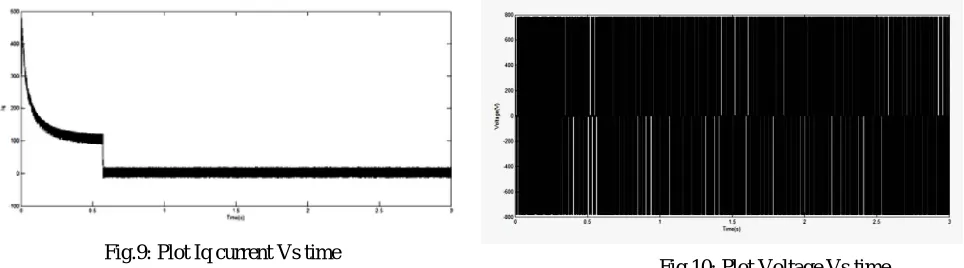
Fig.9: Plot Iq current Vs time
Fig.10: Plot Voltage Vs time
The plots of the direct axes (id) and quadrature axes currents (id) versus time are shown in Figs.8 and 9, respectively. It can be noticed that the machine reaches the set reference speed of 955 rpm in a time interval of 0.58 second.
The terminal voltage of induction motor shown in Fig.10. The variation of 3-phase rotor currents (ir-abc) with time is
shown in Fig. 11. It observes that at lower speeds, the slip is more, and hence the flux required to develop the suitable torque is also more.
Fig.11: Plot rotor current (Iabc) Vs time Fig.12: Plot Idq current Vs time
Fig 11-12 Shows the response of the rotor current and Idq current as the speed of induction motor is controlled at
reference point.
The variation of the stator currents (is-abc) with time is shown in Fig.13. This shows that the stator current reduces when
the machine reached at the set point and the controller operates to maintain the speed constant.
Fig.14: Plot speed Vs time Fig.16: Plot slip Vs time
From the simulation results of the speed shown in Fig.14 using the Mamdani control strategy, it was observed that the speed reaches its desired set value (becomes stable) at 0.58 second. They then reach the final steady-state value. The motor speed increases linearly up to the set speed of 955 rpm in 0.58 second.
Torque characteristics for a set reference speed of 100 rad/second (955 rpm) are shown in Fig.15. From this figure, conclude that when the motor operates at lower speeds, the slip is more. Hence, more torque requires attaining the set speed. Once the machine reaches the set speed of 955 rpm, the average torque of the machine becomes nearly zero.
Fig.16 shows the variation of slip vs. time characteristics for a speed of 100 rad/second.
From this simulation result, we infer that the IM attains the set reference speed of 955 rpm in 0.58 second using the Mamdani-FLC scheme. 469 . 0 1800 955 1800 s s N N N S
This has been verified from the results. Note that the slip decreases linearly in a time span of just 0.58 second from 1.0 to 0.469. The load torque is set constant throughout the process of simulation at the value of 2 N-m [12].
VI. CONCLUSION
The fuzzy control technique is used to obtain the desire speed for improving the speed of the induction motor for the desire task has been investigated in this paper. Simulink model is developed in Matlab R2009a with Fuzzy controller is implemented in the vector controlled induction motor. In this the fuzzy controller produces the control output to control the induction motor parameters. The controlling torque is produced by the fuzzy controller which control the quadrature current of the induction motor to produce the desire value. For the implementation of the fuzzy controller 49 rules are designed on which the fuzzy controller operates. In the fuzzy editor two input and one output is selected in which one input is speed error & other is change in error and output is controlling torque whose limits are set to provide better result. Triangular membership function is used in the input of the fuzzy controller and centroid method foe de – fuzzification. The result obtained by using fuzzy controller is much better than the conventional control method as the speed become constant at 0.58 second which represents the better performance. The main advantage of the Fuzzy controller scheme is that it increases the dynamic performance & providing good stability. The developed control strategy is simple, reliable and easy to implement in real time..
REFERENCES
[1] Bose B.K., “Modern Power Electronics & AC Drives,” Pearson Education, Inc. New Delhi, India, 2002. [2] P. Vas, Vector Control of AC Machines, Oxford University Press, London, UK, 1990.
[3] Hossein Ebadi Kalhoodashti and Mehdi Shahbazian, “Hybrid Speed Control of Induction Motor using PI and Fuzzy Controller”, International Journal of Computer Applications, Vol. 30, No.11, pp. 44-50, September 2011.
[5] C. M. Liaw, Y. S. Kung, and C. M. Wu, “Design and implementation of a high performance field-oriented induction motor drive,” IEEE Trans. Indust. Electron., vol. 38. no. 4. pp. 275-282, pp. 275-282, 1991.
[6] Safdar Fasal T K , U nni Krishnan L, “A Performance Study of PI controller and Fuzzy logic controller in V/F Control of Three Phase Induction Motor Using Space Vector Modulation”, Department of Electrical and Electronics Engineering, Vol. 1, No.2 , pp:121-125, 2013 [7] Sivanandam S.N., S. Sumathi and S.N. Deepa, “Introduction to fuzzy logic using Matlab,” Springer-Verlarg Publications, Hiedelberg,
Germany, 2007.
[8] J.C. Kolte, S.W. Chiwande, “Induction motor parameters control by simulink model”, PISER(progress in science and engineering research journal) 13, Vol.02, Issue: 03/06 May- June; Bimonthly International Journal Page(s) 292-298.
[9] L. A. Zadeh, “Fuzzy set.” Information and control, vol. 8. pp. 338-353 1965.
[10] P. P. Pillay and V. Levin, "Mathematical Models for Induction Machines," in Conference Record of the 30th IEEE-IAS Annual Meeting, IAS'95, Orlando, FL, vol. 1, pp. 606-616, Oct 1995
[11] Ashok Kusagur, S. F. Kodad, B.V. Sankar Ram, “Modelling of Induction motor & control of speed using hybrid controller technology” Journal of Theoretical and Applied Information Technology, Vol. 10, No. 2, pp 117-126, Dec 2009