Adaptive Power System for Controlling Dynamic Loads of an
Induction Motor
D.Reshma Begum & B.Naga Lakshmi
1M Tech student of Dr Kvsrit, Kurnool, India.
2Assistant Professor, Department of Eee, Dr Kvsrit, Kurnool,India.
ABSTRACT
The Navy's future and close term high-vitality sensors also, vitality weapons will expend a substantial segment of the assets of the planned ship stage. A considerable lot of these new frameworks will have extraordinary dynamic power supplies, including both periodic and aperiodic qualities. These dynamic utilities can cause sudden changes in control at the prime power system that can focus to platform frameworks, both to the generators and prime movers and also other loads sharing the regular dissemination transport. This paper presents the utilization of new adaptive power framework (APS) to moderate the negative impacts required on induction motor variable speed because of extensive dynamic loads. A notional size of the equipment required to execute the APS configuration is introduced along with simulation results about confirming the concept.
Keywords— AC/DC converter, electromagnetic load
torque, energy storage, ferrite, frequency modulation, generators, governor, harmonics, nano crystalline, power factor, power quality, prime movers, pulsed load, regulation, shipboard platform, silicon carbide, Simulink,.
I. INTRODUCTION
A block diagram of a conventional shipboard power system is shown in the dashed box of Figure 1.1 Conventional systems have focused heavily on providing well-regulated voltages and clean power to the corresponding load. If the voltage dynamics seen at the load are to be minimized, the output impedance of each converter stage is minimized by using small series inductance values, large shunt capacitance values, and control loops with high bandwidths. However, this type of system does little to prevent the mid to low frequency load dynamics from propagating back to the distribution bus and generator.
If the dynamic profiles propagate back to the ship’s electric plant, significant power quality issues and
generator/distribution losses can occur [1], [2]. In addition, the dynamic pulse loading may cause wear and tear on the gensets’ mechanical parts [3]–[5]. Torsional stresses to the shaft of the ship’s prime mover can result due to the very large and quickly changing electromagnetic load torques. These dynamic electromagnetic load torques may also excite the shaft’s torsional resonances, typically referred to as sub-synchronous resonances [2], [6], adding additional stresses to the shaft.
Present-day methods that can be used to buffer the prime power system from dynamic loads include the following:
Figure.1.1A block diagram of a notional power system with the APS attached 1. The “brute-force method”, where by passive
filters are used to smooth the dynamics of the load profile. Al though this method results in minimal additional power losses, achieving the smoothing or filtering needed by the shipboard power system requires filter sizes and weights that are impractical and prohibitive for ship installation.
from the large additional power dissipation, increasing both cooling requirements and fueling costs for ship platforms.
3. The “restricted-timeline method”, which requires a defined charging time for the system whereby the pulse power can only be supplied at predefined scheduled time intervals. For these systems, the successive launch times or fire times (repetition rate) and corresponding system performances are limited by the charging times of the system. Some examples of such systems are the Electromagnetic Aircraft Launch System (EMALS) and rail guns [8], [9].
Consequently, a new approach is needed to manage the load dynamics of emerging Navy systems – one that is not compromised by the disadvantages noted above for existing systems. The new Adaptive Power System (APS) specifically addresses this need. The APS can be used to efficiently mitigate bus disturbances and reduce stress to the shipboard gensets by converting the dynamic power load seen by the shipboard power system into an equivalent rolling time average – essentially serving as an active low pass filter to the load dynamics.
Figure.1.2 An overview of the functionality of the APS system
As shown in Figure 1.2, the APS can be added to an existing system. The APS consists of energy storage, a passive power filter, a bi-directional current source, and innovative control loops, as shown in Figure 1.2. The bi-directional current source efficiently delivers the pulsed
power demand from the APS energy storage to the desired sensor or weapon system, thus providing a buffer to the upstream power equipment.
The APS can support the pulsed load at a fraction of the size and weight needed when compared with the passive filter method (brute-force method), without excessive power dissipation as would exist if using the active load method (throw-away method), and for some specific applications without timeline restrictions as would be needed if using a refresh or recharging type system (restricted-timeline method).
If for all of the desired combinations for duty cycle, repetition rate, and peak power levels, the average power over a load cycle is within the allotted generator power, the APS can be designed such that no timeline restrictions exist. This is the case for the example of the 300-kW system given in Section III. On the other hand, if there are profiles whereby the average power is above the generator capability, the APS can be used to provide the needed delta in power, allowing this enhanced operation of the sensor/weapon for short periods of time. The time limit for the enhanced operation is limited by the APS size, the size of the energy storage needed to provide the delta power, and the maximum average power allowed. This maximum allowed average power determines the corresponding duty cycle of this enhanced operation and hence the quickest allowed recharge time of the APS energy storage.
removing the harmonic currents (or for DC systems, the PWM switching currents and corresponding harmonics) riding on top of the average power draw. These noise current magnitudes are usually much less than the fundamental or DC current magnitude.
Conversely, for the new sensors and weapons it is not just a matter of removing a small level of noise riding on top of the average power draw. For these types of loads, the average power draw is not constant and may vary greatly. In addition, these dynamic loads not only produce noise at harmonic frequencies but also large levels of noise at inter harmonic (not multiples of 60 Hz) and sub-harmonic (less than 60 Hz) frequencies. With the proper use of control loops and energy storage, the APS can reduce the rate at which the power demand on the generator changes, thus limiting the dynamics and spectral content seen by the generator - transforming a weapon or sensor system that had otherwise been incompatible with the platform’s power system into one that is now feasible.
II. ADAPTIVE POWER SYSTEM (APS)
Adaptive Power Systems (APS) was created in 2003 to manufacture and distribute a complete and extensive line of AC and DC power equipment to meet world-wide applications.
Adaptive Power System products are designed to fill the needs of power conversion for either AC or DC applications. Our AC to AC converters provide frequencies and voltages found around the world for both commercial and military avionics or shipboard applications. Each system includes features that customers have asked for over the years. For instance, each unit in the APS product range will accept multiple frequency and voltage inputs, offers fully adjustable output frequency and a very broad adjustable voltage range that permits the duplication of any utility power configurations. The APS range is available in sizes from 500 VA to 120 kVA.
Figure.2.1 The power ripple filtering requirement of
the APS
Operation of the Adaptive Power System is as follows:
a. The current provided from the upstream power system is regulated by the APS to be equal to the filtered (0.13 Hz) current profile of the load demand. The compensation block regulates Ibus
to be equal to Iref by controlling the output
current of the bi-directional current source (BDCS); see the bus-current and BDCS-current waveforms in Figure 4.1. The BDCS is a DC/DC converter that can process power in both directions – it can both absorb and deliver power.
b. Hence, the AC component or dynamics of the load profile is not part of Ibus but is provided by
the energy-storage capacitance via the BDCS. c. The energy-storage capacitance value is selected
to be large enough to provide the source and sink currents to support the pulsed load demand. The value for the energy-storage capacitance is minimized by allowing the voltage across Cstore
to vary significantly, where Udelivered = 12
Cstore(Vt20 − Vt2+), minimizing the energy
storage capacitance required.
II. The voltage variation across Cstore is also
decoupled from the load, allowing tight regulation of the bus voltage seen by the load to be maintained. Udelivered is the
energy delivered or absorbed by the storage capacitance, and Vt0 and Vt+ are the corresponding voltages across the energy-storage capacitance just prior to the load disturbance and after the energy-storage capacitance has delivered or absorbed the desired energy.
d. The current reference, Iref, is slowly adjusted to
keep the voltage across Cstore within the
allowable boundaries. This is achieved by regulating the energy stored in Cstore via a
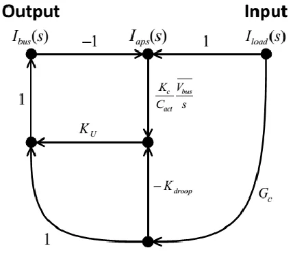
slow-moving outer loop. The block labeled Ku in Figure 4.2 sets the bandwidth of the outer energy loop while K droop is used to optimize the energy utilization of Cstore.
Controlling the load dynamics is accomplished by properly selecting the corner frequency for the 0.13-Hz signal filter in the current feedback path to be lower than the genset’s control loop bandwidths. The corner-frequency selection for the signal filter is the critical design parameter in the APS that controls the protection provided to the generator and prime mover; hence this filter sets the allowed power ramp rate and dynamics seen by the generator.
Figure.2.2 Signal flow graph of APS for low frequency energy loop design where
Ibus = Iref and Iload = Iload
To limit the bandwidth requirement of the APS, a low-pass filter between the APS and the load is used. The low-pass filter reduces the response-time requirement on the APS by reducing the high-frequency components of the load pulses seen at the bus connection to the BDCS. The corner frequency for the low-pass filter is approximately 160 Hz. The APS can both sink and source current through the BDCS, which is implemented with an efficient high-frequency DC/DC converter. Because the pulsed power is no longer provided by the generator, the value of Cstore must be selected large
enough to provide the source and sink currents to support the pulsed load demand in the time consistent with the 0.13-Hz signal-filter time constant, while concurrently maintaining the voltage across Cstore within its defined
allowable range. The voltage range on Cstore is indirectly
controlled by regulating the energy stored in Cstore. The
current command, I ref, is slowly adjusted to maintain the proper energy storage, thus keeping the proper voltage range across Cstore. Energy regulation is chosen over
voltage regulation to linearize the outer loop transfer function with respect to the BDCS controlled output current. Energy regulation eliminates the outer loop dependency on the duty cycle of the BDCS. The duty cycle of the BDCS varies with the voltage across Cstore.
Because the transfer function is
independent of the voltage across Cstore, as desired the
outer bandwidth will remain constant as the voltage across Cstore changes. If a voltage loop is used instead, the
outer-loop bandwidth will vary with the DC operating point, potentially affecting performance.
III. SIMULATION RESULTS
The generator model used in the simulation is based on Simulink’s Synchronous Machine standard sixth-order electrical model and is rated for 2.28 MVA. The AVR (voltage) control loop is set at 0.6 Hz and the governor (speed) control loop is set at 1 Hz. The AC/DC converter is an 18-pulse diode rectifier model with an output filter corner frequency of approximately 20 Hz. The major models used to create the AC/DC converter are the three phase-shifting transformers and the 6-pulse diode rectifiers, both from Simulink’s Sim Power Systems toolbox [21].
The DC/DC converter voltage control loop is set at 100 Hz. The DC/DC converter is modeled using the standard non-switching average model, which uses an ideal transformer for transforming DC and AC information with the transformer turns ratio controlled by the converter duty cycle [17]. This same technique is used to model the APS bi-directional current source. To demonstrate the effectiveness and benefits of the APS, Figures provide simulation results for various waveforms in the system when a dynamic load is applied both with and without use of the APS. For this simulation, the generator is biased with a 0.6 p.u. load prior to applying the dynamic load.
Figure.3.2 Waveforms with APS
As expected, the generator’s voltage and prime-mover’s speed (frequency) disturbances are much smaller with the use of the APS. The frequency and voltage modulation created by the load without the APS demonstrates that a nominal system of this size encroaches on the respective modulation limits of 0.5% and 2% set by MIL-STD-1399-680 [14]. A larger load or this load combined with other ship loads could result in a noncompliant system.
The genset model used does not simulate mechanical behaviors of the generator, such as shaft or other mechanical resonances. However if shaft resonances are excited (e.g., sub synchronous resonances), significant torques larger than the full-load steady-state torque could be seen on the shaft [6]. Furthermore, if these disturbances exist, mechanical stresses to other parts of the genset can also occur. As is evident in the results, the APS significantly reduces frequencies that could excite potentially dangerous mechanical resonances as well as cause fatigue due to excessive movements.
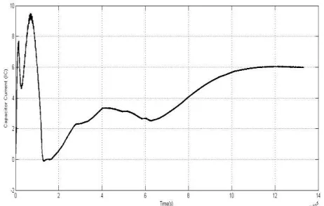
Figures also shows the voltage waveform of the storage capacitor and the current waveform of the bi-directional current source, demonstrating the APS’s capability of providing the dynamic demand of the load resulting in the generator only having to provide the rolling average of the load power profile. The 375-V bus voltage delivered to the load, indicating that the ±5% transient regulation requirement is met. At time 6.5 seconds in, the load switches to a constant load and the APS consumes no power (APS output current goes to zero) after about 5 seconds from this point in time, demonstrating the efficient conditioning method provided by the APS. If the APS is used for a periodic dynamic load application, the generator
will see essentially a constant load with only a benign very small power ripple riding on top of the load’s average power draw.
Above figure demonstrates the filtering capability of the APS in the frequency domain. The solid blue line in this figure shows the load rejection provided by the APS as viewed from the output of the upstream 375-V converter. The proposed filtering requirement (dashed red line with the 100% and the 3% limits annotated) has been superimposed on the APS results, showing that the APS satisfies the requirement. As can be seen from Figure 3.2, the APS removes the low to mid frequencies that can degrade the generator shaft or could excite potentially hazardous resonances. In addition, removing these frequencies from the electric plant distribution bus means the bus quality for other users is improved – meaning fewer disturbances will exist due to the load dynamics interacting with the bus impedances and the generator.
Figure.5.3 Waveforms of induction motor using APS
V.
CONCLUSION
The Adaptive Power System (APS) concept presented in this paper can be an enabling technology for sensors or weapons with large dynamic loads, which without the APS would be incompatible with the upstream shipboard generator and distribution bus. The APS consists of energy storage, a bidirectional current source, and innovative control techniques. These innovative control techniques increase the energy storage utilization, thus minimizing the energy storage size. In addition, because of the linear behaviour of the outer-energy loop regulation technique, performance is maintained overall operating conditions. The APS shapes the dynamics seen by the generator to be slower than the response times of the prime-mover’s speed or generator’s voltage regulation loops, thus allowing the genset to maintain speed and voltage regulation during these large load dynamics. Not only can the APS help to maintain generator/prime-mover reliability, but the APS can also be used to improve sensor/weapon performance or improve metrics such as system weight, cooling demands, and ship fueling costs. Performance of the APS has been demonstrated through the use of Matlab Simulink simulations. Calculated losses and size of a 300-kW system have also been provided, demonstrating that the APS is a viable solution for integrating high-energy sensors and weapons onto Navy platforms.
[1] F. Kanellos, I. Hatzilau, and J. Prousalidis, “Investigation of voltage/frequency modulation in ship electric networks with pulsed loads according to stanag 1008 design constraints,” in All Electric Ship Conference, 2007.
[2] IEEE Recommended Practices and Requirements for Harmonic Control in Electrical Power Systems, IEEE Industry Applications Society/Power Engineering Society Std. 519-1992, 1993.
[3] M. Baldwin, “Electric arc furnace impact on generator torque,” in Power Systems Conference and Exposition, 2004. IEEE PES, 2004, pp. 776– 780 vol.2.
[4] G. J. Tsekouras, F. D. Kanellos, J. M. Prousalidis, and I. K. Hatzilau, “Stanag 1008 design constraints for pulsed loads in the frame of the all electric ship concept,” Nausivios Chora, vol. 3, pp. 113–152, 2010. [Online]. Available: http://nausivios.snd.edu.gr/nausivios/docs/b3 2010. pdf
[5] H. Smolleck, S. Ranade, N. R. Prasad, and R. Velasco, “Effects of pulsed-power loads upon an electric power grid,” Power Delivery, IEEE Transactions on, vol. 6, no. 4, pp. 1629–1640, Oct 1991.
[6] D. N. Walker, S. L. Adams, and R. J. Placek, “Torsional vibration and fatigue of turbine-generator shafts,” Power Apparatus and Systems, IEEE Transactions on, vol. PAS-100, no. 11, pp. 4373–4380, 1981.
[7] M. Butler, G. Dakermanji, L. Goliaszewski, D. Kusnierkiewicz, J. Tarr, D. Temkin, and U. Carlsson, “Fault tolerant shunt regulator for a spacecraft thermionic nuclear reactor,” AIP Conference Proceedings, vol. 324, no. 1, pp. 39–44, 1995. [Online]. Available: http: //scitation.aip.org/content/aip/proceeding/aipcp/10.1063/1 .47196
[8] M. Doyle, D. Samuel, T. Conway, and R. Klimowski, “Electromagnetic aircraft launch system-emals,” Magnetics, IEEE Transactions on, vol. 31, no. 1, pp. 528– 533, Jan 1995.
[9] J. Bernardes, M. Stumborg, and T. Jean, “Analysis of a capacitor-based pulsed-power system for driving long-range electromagnetic guns,” Magnetics, IEEE Transactions on, vol. 39, no. 1, pp. 486–490, Jan 2003. [10] B. Singh, K. Al-Haddad, and A. Chandra, “A review of active filters for power quality improvement,” Industrial Electronics, IEEE Transactions on, vol. 46, no. 5, pp. 960–971, Oct 1999.
[11] H. Akagi, “New trends in active filters for power conditioning,” Industry Applications, IEEE Transactions on, vol. 32, no. 6, pp. 1312–1322, Nov 1996.
[12] ——, “Active harmonic filters,” Proceedings of the IEEE, vol. 93, no. 12, pp. 2128–2141, Dec 2005.
[13] D. Hamza and P. Jain, “Conducted emi noise mitigation in dc-dc converters using active filtering method,” in Power Electronics Specialists Conference, 2008. PESC 2008. IEEE, June 2008, pp. 188–194 [14] High Voltage Electric Power, Alternating Current, Department of the Navy Std. MIL-STD-1399-680, 2008. [15] Governing Systems, Speed & Load-Sensing Naval Shipboard Use, De partment of the Navy Std. MIL-G-21 410A, 1991.
[16] Regulator-Exciter Systems, Voltage, A.C. Generator, Naval Shipboard Use, Department of the Navy Std. MIL-R-2729D, 1992.
[17] N. Mohan, Power electronics : a first course. Hoboken, N.J: Wiley, 2012.
[18] R. Dorf, Modern control systems. Upper Saddle River, N.J: Pearson Prentice Hall, 2011.
[19] J. Klein, “Synchronous buck mosfet loss calculations with excel model,” Fairchild Semiconductor, no. AN-6005, November 2014.
[20] L. Kvarnsjo, “Green inductive components,”¨ Special Report – Green Power, 2009.