Study of Flow Forming Process Using a
Non-Newtonian Lubricant
Vikas Kumar Sharma
1, Surender Kumar
2Associate Professor, Dept. of Mechanical Engineering, GLA University, Mathura, U.P., India1 Professor, Dept. of Mechanical Engineering, GLA University, Mathura, U.P., India2
ABSTRACT: During flow forming various soaps are frequently used as lubricant whose characteristics are approximately by a non Newtonian fluid. In this paper the lubrication problems of flow forming has been studied, assuming the lubricant as a non Newtonian one, whose viscosity is function of pressure also. The analysis is initially covered by neglecting elastic deformation of the blank and the roller and then by considering the elastic deformation of both blank and the roller which are generated by the pressure of the fluid. The analysis includes the pressure distribution, shear stress and film thickness. The results so obtained are presented graphically and discussed critically.
NOMENCLATURE
Unless otherwise specified, the following symbols have been used in the paper 𝑐 Clearance between the roller and the mandrel
𝐷𝑅 Diameter of the roller
𝑑 Diameter of the mandrel
𝐷 Reduced diameter
𝐷0 Diameter of the under formed blank
𝐸𝑅 Young’s modulus of the roller material
𝐸𝐵 Young’s modulus of the blank material
𝐸0 Equivalent young’s modulus of the roller and the blank ℎ Thickness of the oil film at any point outside the contact zone
ℎ0 Thickness of the oil film squeezed into the area of contact between the roller and the blank 𝒉𝟎= ℎ0 𝑋2
𝐷 Dimensionless thickness of the oil film squeezed in the area of contact between the roller and the blank
ℎ𝑠 The gap between the roller and the blank
𝑁 Speed of rotation of the mandrel in rpm.
n Constant (non Newtonian parameter)
𝑝 Pressure
𝑝0 1
γ 1 − exp −γp Reduced pressure of the lubricant
𝑝𝑚 Mean pressure at the contact area
𝑞 Load per unit length
𝑟𝐴 Radius of the point of contact of the roller and mandrel
𝑡 Thickness of the blank
𝑡0 Thickness of the undeformed blank
𝑈𝑅 Peripheral velocity of the roller
𝑈𝐵 Peripheral velocity of the blank
𝑈 = 𝑈𝑅+ 𝑈𝐵 Peripheral velocity of the blank and the roller at the contact zone
𝑉 Feed of the roller
𝑊𝐵 Deflection of the surface of the blank
𝑋0 Width of contact in the direction of revolution
X Dimensionless value of 𝑋, 𝑋
𝑋0
𝑋𝑜𝑒 Width of elastic contact in the direction of revolution 𝑋𝑜𝑝 Width of contact of the roller and the blank
∆𝑦 Reduction of thickness per revolution of blank
𝛼 Semi angle of the conical mandrel
𝛾 Pressure exponent of viscosity of the lubricant
𝜇0 Absolute viscosity of the lubricant at atmospheric pressure 𝑣𝑅 Poisson’s ratio of the roller material
𝑣𝐵 Poisson’ ratio of the blank material
𝜌𝑅 Radius of round off of the roller
𝜌𝑀 Radius of round off of the mandrel
I. INTRODUCTION
Flow forming is a process for forming sheet metal into the components having axisymmetric like cones, hemispheres or other circular shapes by a combination of rotation and deformation [1-3]. In this process a roller moves along the surface of a mandrel, while the mandrel rotates about its axis with a blank when the working forces is small, blank can be spun without the use of any lubricant, provided that the feed of the roller and the rotation of the blank are kept within the limits of the small critical values, so as to keep the blank surface from being torn off and resulting flakes of metal from sticking the roller. It is economical then other forming processes and can be used for larger production at lower cost [4]. Blank size upto 2 m can be deformed successfully. As the tube diameter reduces, the surface roughness and force increases [5]. In this process the wrinkle failure, the time and the material wastages is significantly reduced whereas product quality, production efficiency and processes repeatability has improved [6]. This accounts for the use of some sort of lubricants e.g. various types of greases, metallic soaps (sodium and lithium soaps etc) tallow etc. in flow forming [1]. Thus study of the lubrication is of importance in flow forming. In one of the studies of the flow forming [7] the lubricant has been assumed to have Newtonian character. Lubrication studies in deep drawing & cold forging operations have been reported recently [8-11]. It has been shown that the behavior of the metallic soaps (sodium and lithium soaps etc.) and other lubricants, generally used in forming, approximates to that of a power law fluid [12]. The author has not come across any work in the area of Flow forming carried out systematically by considering by the non-Newtonian characteristic of the lubricant. As per the previous knowledge no work has been done, which takes into account the non Newtonian properties of the lubricant. Therefore, the aim of the present paper is to develop and discuss the theories of hydrodynamic lubrication of flow forming process, considering the lubricant as a power law fluid.
II. ANALYSIS OF LUBRICATION IN FLOW FORMING
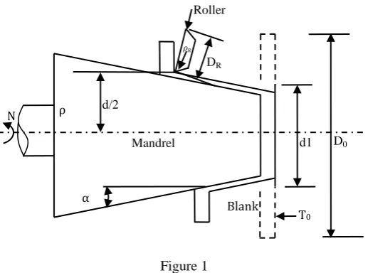
Figure 1
Figure 1 shows the flow forming process in which rotating disc of sheet metal is fixed on a conical mandrel, is deformed into a cone shaped cup with the roller. The clearance c between the roller and the mandrel is kept to be 𝑡0𝑠𝑖𝑛𝛼 if the roller is assumed to be in contact in a way shown in figure 2 with the blank near the top of the roller (this assumption means two dimensional contacts of two discs). The width of contact in the direction of revolution is given by the equation
X0= D∆y ` (1)
Figure 2
Figure 2 showing the Schematic Diagram of Flow Forming Lubrication with the oil film squeezed thickness into the area of contact between the roller and the blank
Where D, the reduced diameter is given by D = DR.d
DR+d (2)
In the above relation, the thickness of the blank t is assumed to be small as compared to the diameter of the mandrel, d, so d
2+ t = d 2
Further the lubricant is assumed to be a Non Newtonian one, which is approximated by power law fluid for which
N d/2
Mandrel
Blank
T0 d1 D0
𝜌𝑅 DR
ρ
α
τ= μdudy n (3) And viscosity 𝜇 at a pressure p is given by the relation
μ=μ0. exp γp (4)
The effect of temperature on the properties of the lubricant has been neglected in the analysis. The gap ℎ𝑠between the roller and the blank is given by
ℎ𝑠=𝑋02 𝐷 𝑋
2− 1 (5)
If the thickness of the oil film squeezed into the area of contact between the roller and the blank is equal to ℎ𝑠, the oil gap h at any point outside the contact zone is given by
ℎ = ℎ0+ ℎ𝑠
(6)
III. PRESSURE DISTRIBUTION
The Reynolds’s equation for the power law fluid is [15] dp
dX =
n+1 2n+1 U n
nμ
0exp γp h−h0n
h2n +1 (7)
Where U = UR+ UB Now, h0=
h X 02
D
(8)
Substituting the value of h from equation (8) into the equation (7) and integrating from 𝑋 = 1 𝑡𝑜 𝑋 =∞ we get
p0= n+1 2n+1 n
nμ 0Dn +1 x02n +1 U
n x2−1 n
dX h0+x2−1 2n +1 ∝
1 (9)
Where
p0= e−γpdp = 1
γ e
−γp− 1 p
0 (10)
From equation (10), loge 1 −γp0 = −γp (11)
Therefore it is necessary that p0= 1
γ (12)
FILM THICKNESS
If the peripheral velocity of the blank and the roller at the contact zone is assumed to be same, 𝑈 = 𝜋𝑁𝐷𝑅. Thus the thickness of the oil film squeezed into the area of contact between the roller and the blank is given by
ℎ0= 3𝜋𝑁𝜇0𝛾𝐷𝑅 𝐷
∆𝑦 (13)
IV. SHEAR STRESS
The shear stress 𝝉 for lubricant following power law is given by 𝜏 = 𝜇𝑑𝑢
𝑑𝑦 𝑛
(14)
The value of lubricant film thickness is assumed to be very small, the pressure gradient in the regions is small and hence
du dy =
U
h (15)
Substituting the value of (du/dy) from equation (15) into (14), we get τ= μU
h n
V. ANALYSIS CONSIDERING ELASTIC DEFORMATION
Now, if the elastic deformation of the roller and the blank by the pressure generated with a fluid whose viscosity is itself changed with pressure is considered. Equation (16) is modified by the elasto hydrodynamic equation which has been derived by Ertel and Grubin [2]. In this case, it is assumed that the shape of the surface outside the Hertzian zone is the same whether a lubricant is there or not. The width of contact 𝑋𝑜𝑝 is given by
Xop = D ∆y + WR+ WB (17)
According to the theory of contact by Hertz, elastic contact width in the direction of revolution, 𝑋𝑜𝑒is given by
Xoe = 4PmD
E0 (18)
Where 𝑃𝑚 is the mean pressure at the area of contact and 𝐸0 is given by
1 E0=
1−VB2
πER + 1−V B2
πEB (19)
Using the equation (18) and (19) equation (17) becomes
Xop = D ∆y + 16pm2 DE 0
2 (20)
When the deformation of the roller and the blank by the pressure generated by the lubricant is also considered, value of ℎ𝑠 is given by
hs =x2
D + WR+ WB− ∆y (21)
According to the theory of contact by hertz, the pressure distribution produced by the contact of two discs is semielliptical. Taking this fact into account, equation (21) can be written as
hs = 2q E0
X Xoe
X2
X2oe− 1 − loge X Xoe +
X2
Xoe2 − 1 − ∆y (22)
Where q is the load per unit length and is given by
𝑞 = 2𝑋𝑜𝑒𝜌𝑚
Now the expression within the square brackets in equation (22) can be approximated in the range 1 ≤ X Xoe ≤ 1.8 by 2.114 X
Xoe − 1 1.55
to a very high accuracy [8]. Thus equation (22) may be written as
hs =2q
E0 2.114 X Xoe − 1
1.55
− ∆y (23)
VI. PRESSURE DISTRIBUTION
In this case also, the Reynolds’s equation (7) has the same form, but here 𝒉𝒔 = 𝒉 − 𝒉𝟎is given by equation (23) in place of the value given by equation (5) in the previous case, where the elastic deformations of the roller and the blank were neglected. Thus in this case. Reynolds’s equation (7), takes the following form,
dp dx =
n+1 2n+1 U n
n
μ0eγp q
E0 4.228 X Xoe − 1
1.55 − ∆y
n
/ 3πNμ0γDR D ∆y+
4.228 q E0
X Xoe − 1
1.55 − ∆y
2n+1
Integrating equation (24)
p0=
n+1 2n+1 n
n μ0UnX′
oeeγp q
E0 4.228X′
1.55− ∆y
∞
1
n
dx′/ 3πNμ0γDR ∆Dγ+4.228
E0 x′− 1
1.55− ∆y 2n+1
(25) Where X’ = 𝑋
𝑋𝑜𝑒 and 𝑝0 is given by equation (10)
The integral on the R. H. S. of equation (25) can be evaluated for different values of n.
VII. CALCULATION OF SHEAR STRESS
The shear stress for a lubricant following power law is given as in the previous case, by
𝜏 = 𝜇𝑑𝑢 𝑑𝑦
𝑛 = 𝜇𝑈
ℎ 𝑛
(26)
But in this case, value of ℎ𝑠 is given by equation (21), as compared to the previous case, where ℎ𝑠 was given by equation (5) and h is given by equation (6).
VIII. DISCUSSION AND CONCLUSIONS
In the present paper, an analysis of the lubrication of flow forming has been presented, considering the lubricant as a power law fluid. The value of non-Newtonian parameter n will vary within reasonable limits and this variation will have considerable effects on the hydrodynamic pressure and the shear stress distribution. The values of various parameters associated with a typical case of flow forming are given below which are based on the process of deformation and the properties of the lubricant.
D (diameter of mandrel at the section under consideration) = 70 mm.
DR = 120 mm, 2α= 450,μ0= 1.02 X × 10
−4kgsec
mm2 ,γ= 7.12 × 10 −2 kg
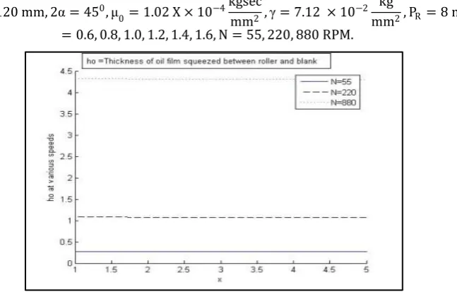
mm2, PR = 8 mm, n = 0.6, 0.8, 1.0, 1.2, 1.4, 1.6, N = 55, 220, 880 RPM.
Figure 3
In figure 3 the values of the thickness of oil film squeezed between the roller and blank does not varies throughout the contact length. Whereas in figure 4 the value of oil film thickness gradually decreases along the length.
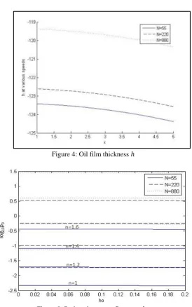
Figure 4: Oil film thickness ℎ
Figure 5: Reduced pressure P0 versus h0
In figure 5 reduced pressure 𝑝0 of the lubricant vs. ℎ0the dimensionless thickness of oil film squeezed in the area of contact between the roller and the blank have been plotted for different values of n and N for 0.01 ≤ ℎ0≤ 0.2. It has been found that as the value of n increases from 1.0 to 1.6 the value of 𝑝0 goes on rising. However the value of p0 are
negative for n=1 to 1.6 at N=55 whereas n=1 the value of p0 is also negative at N=880 but increases and remain
positive for higher value of n and remain constant throughout film thickness (h0). In order to avoid the zone of negative
Figure 6: Shear stress τ versus x
In figure 6 value of 𝜏 the shear stress in the lubricant film, have been plotted for various values of n and N. from this figure, it can be seen that as the value of n increases from 1 to 1.6 the value of shear stress gets reduced for all the values of x. Also for a value of n the shear stress 𝜏 goes on increasing as the value of N increases from 55 to 880 RPM. For the point 𝑥 = 𝑥0 the value of x, corresponding to the point of contact of the roller and the blank), it is seen that for a given value of n, the shear stress τ is the same for all the values of N. however, as n increases from 1 to 1.6 value of τ at x = x0goes on reducing and is smallest for n=1.6. From the above it is clear that the shear stress in the lubricant film goes on reducing as n increases form n = 1 to 1.6, although the pressure𝑝0, developed in the oil film, is larger in magnitude for a larger value of n, so a more viscous lubricant (having a larger value of n, the non Newtonian parameter) is more suitable for flow forming, although the pressures developed are higher in this case.
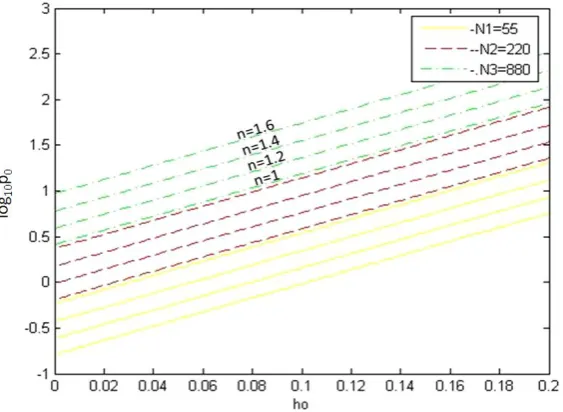
In figure 7 the reduce pressure p0 of the lubricant vs. h0 the dimensionless thickness of oil film squeezed in the area of
contact between the roller and blank have been plotted for the different value of n & N for 0.01≤ ℎ0≤ 0.2 by considering elastic deformation. It has been found that as the value of n increases p0 goes on increasing and also
gradually increases as the film thickness increases. As the process of flow forming are generally carried out at high deformation pressure with lubricant of high value of Newtonian parameter, it is better to find out the value of pressure and shear stress distribution by considering elastic deformation taking place during the process.
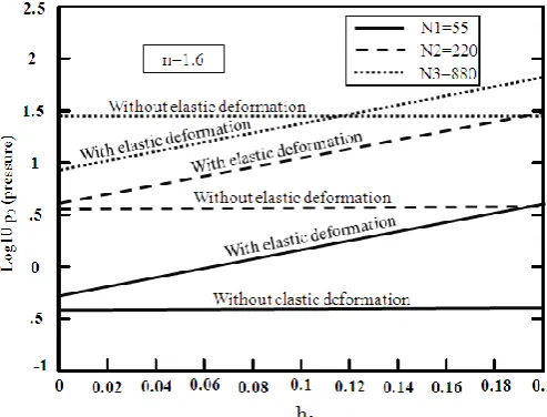
Figure 8: log10 (Pressure) versus thickness graphs with and without elastic deformation
Figure 8 shows the superimposition of the reduce pressure p0 of the lubricant vs. h0 the dimensionless thickness of oil
film squeezed in the area of contact between the roller and blank with and without elastic deformation have been plotted for the different value. It has been observed that at high speed (N≅650 rpm), it is advisable that the process is to be carried out without elastic deformation in order to avoid the deformation of the component
The solution can be extended by considering the effect of temperature on viscosity of lubricant, if needed. It is evident that it is better to use high viscosity lubricant for flow forming process to have better accuracy and precision.
APPENDIX I
The integral in equation (9) can be split up into two integrals in the following way
𝑥2−1 𝑛𝑑𝑥 𝑥2−1+ℎ0 ∞
1 =
𝑑𝑥 𝑥2−1 𝑛 +1 ∞
1 − 2𝑛 + 1 ℎ0
𝑑𝑥 𝑥2−1 𝑛 +2 ∞
1 =
𝜏 2𝑛 +1 2 𝜏 −𝑛 2𝜏 1
2
− 2𝑛 + 1 ℎ0 𝜏
2𝑛 +3 2
2 𝜏 −𝑛+1 2𝜏 1
2
(1B) The above integral can be evaluated for various values on n, as the values of gamma function are available in mathematical handbooks [14].
When n=1, the integral in (9) has the value ( 1
4ℎ0) according to [2] in the range 0.01 ≤ ℎ0≤ 0.2.
APPENDIX II
∆y =
PR2− X−V 2 − PR2−X2 dx 3v /2
v /2
v
(1C)
Figure 9: Geometry for calculation of ∆y
∆y =PR
4 3 1 − v 2PR
2
− 3 1 − 3v 2PR
2 +
1 v v P R
− 3sin−1 3v 2PR− sin
−1 3v
2PR (2C)
∆y Can be calculated for various values of feed of roller, v and radius of round of, Pr of the roller.
APPENDIX III
In the present paper the effect of pressure on the viscosity of the lubricant has been taken into account. The viscosity 𝜇 at pressure p is given by the relation
𝜇 = 𝜇0𝑒𝛾𝑝
Figure 10: reduced pressure p0 versus pressure p
REFERENCES
[1]. Spinning, Metals Handbook Desk Edition, American Society for Metals, 1985.
[2]. K. Lange, Metal Spinning, Handbook of Metal Forming, Society of Manufacturing Engineers, 1985, p 21.1-21.14. [3]. Metals Handbook, American Society for Metals, Vol.4.
[4]. H. Palten and D. Palten, Met. Form, Sept 2002.
[5]. Yao Jianguo, and Murata Makoto, “An experimental study on paraxial spinning of one tube end”, Journal of Materials Processing Technology 128 (2002) 324-329.
[6]. Dr. R. Uday Kumar, “A study on deep drawing and spinning process in sheet metal forming, “International Journal of Application, 2012, pp. 170-175.
[7]. Hayama, M., “Study of Lubrication in Shear Spinning”, Bulletin of the Faculty of Engineering, Yokohama National University, Vol. 20, March 1971, p. 61.
[8]. Luiz Mauricio V. Tigrinho and Ricardo Adriano dos Santos, “Experimental investigation on the influence of the lubricant type in the punch stretching of extra deep drawing steel”, Anselmo Eduardo Diniz, Vol.XXX, No. 4, ) Oct-Dec 2008.
[9]. Kim, H., Sung, J.H., Sivakumar, R., Altan, t., November 2007, “Evaluation of stamping lubricants using the deep drawing test”, International Journal of Machine Tools & Manufacture, Volume 47, Issue 14, pp. 2120-2132.
[10]. Kumar, D.R., 2002, “Formability analysis of extra deep drawing steel”, Journal of Materials Processing Technology 130-131, pp 31-41. [11]. Xu, Y., august, 2007, “formability Analysis: Finding the Deformation Zone”, Magazine Metal Forming, pp. 36-39.
[12]. Kolmogorov, V. L., Orlov, S. I. and Selishchev, K-P., “Drawing Under Conditions of Hydrodynamic Lubrication”, National Lending Library for Science and Technology, Boston Spa, Yorkshire, England, 1968.
[13]. Cameron, A., “Basic Lubrication Theory”, Ellis Horwood Limited, 1976.