RSE-M NUCLEAR IN-SERVICE INSPECTION CODE
A SET OF MODERN FLAW EVALUATION RULES
Claude Faidy1, Stephane Chapuliot2, Stephane Marie3
1 Consultant, Structural Integrity Mechanical Engineer, AFCEN, France 2 Mechanical EngineeringExpert in Fracture Mechanics, AREVA, France 3 Mechanical EngineeringExpert in Fracture Mechanics, AREVA, France ABSTRACT
After a quick overview of RSEM scope now used for more than 100 Nuclear Power Plants in the World, this paper will present the flaw evaluation rules of RSE-M Appendix 5.
These Appendix consider cracks, volumetric defects and thinning areas. Periodically updated on a yearly bases, the rules cover cracks in different components, for different material, in different location. It consider defects interaction, cladded components, mismatch effects, mechanical and thermal loads, warm pre-stressed …
Crack in brittle and ductile regimes are considered using K and J parameters for different crack shape (surface and sub-surface, inner or outer surface, elliptical or infinitely long cracks) in different location: base metal, weld, underclad, dissimilar welds….
The RSEM Appendix 5 covers: flaw geometry definition, acceptance standards, fatigue and plastic-instability, K-J parameter evaluation, planar defect acceptance criteria, material properties, volumetric defect evaluation, partial safety factors
This paper will be focused on different J estimation scheme presented in detailed in RSEM 2015 edition and last modifications of 2016.
INTRODUCTION
General
The evaluation of the fitness for service of structural components is a key aspect for developing safety justifications for continued operation in many industries concerned with pressurised piping and vessels, and in particular for safety in nuclear power plants. Over the years different countries have developed their own rules in connection with their particular needs and in accordance with their national regulation. With the internationalisation of the nuclear industry and the markets there is now an on-going effort in harmonizing such rules to ensure best practice across the world.
The presentation is focused on light water reactor (LWR) at low temperature (no creep consideration) and based on 2015 edition of RSE-M and RCC-MRx Codes edition 2015 that are totally consistent. Both Codes are developed under AFCEN organization: French Association for Design, Construction and Surveillance Rules of Nuclear Power Plant Components of Nuclear Power Plants. AFCEN is to-day an open international non-profit organization to establish, publish, revise and update detailed and practical rules for the design, manufacture, installation, commissioning and in-service inspection, deconstruction of nuclear components from PWR, Experimental, High Temperature and Fusion reactors.
The flaw evaluation procedures in these 2 Codes have been developed in a very close format with many common experts in Fracture Mechanic from EDF, AREVA and CEA. The rules are in non-mandatory appendices:
RSE-M: "Rules for In-service Inspection of Nuclear Power Plant Components"
The first RSE-M version was published in 1990, and last one in 2016 as the result of more than 20 years of many PWRs in France and outside France. The flaw evaluation based on fracture mechanic analysis of cracked components has been continuously improved from 1990 to 2016 editions. The last Edition 2016 is available in French and in English. The 2002 Edition has been translated and largely used in Chinese RCC-MRx: Design and Construction Rules for Mechanical Components
It's the result of merge of RCC-MR developed for Fast Breeder Reactor (LMFBR) in the 1980 and the RCCMX developed by CEA for Research Reactors (RR) in the same period. The first draft compiled version was issued in 2010 based on RCCMX 2007 and RCCMR 2008, last Edition was published in 2015, in English. It's a complete set of rules for design, material selection, fabrication and welding, examination of safety class mechanical components. To-day, no dedicated In-service Code is available in AFCEN for these type of reactors. Nevertheless, a very detailed fracture mechanic appendix (A16) has been developed for flaw evaluation and leak before break justification at design level.
This paper will consider mainly the Appendix 5 of RSE-M. RSE-M content
The French RSE-M is the Code for Operation and In-Service Inspection of PWR Mechanical Components that include:
‐ the 10-year requalification of pressure systems and components
‐ the periodic In-service Inspection (ISI) and associated qualification of procedure and personnel for performance demonstration
‐ surveillance and monitoring activities
‐ deviation and indications treatment including flaw evaluation (local thinning areas and cracks) ‐ the maintenance requirements including modifications, repair, replacement
All these tasks are under Utility responsibility in French regulation, except requalification which is under Safety Authority responsibility, in any case sub-contracts are acceptable through certified independent bodies or recognized Utility Inspection Service.
A set of appendices covers general information on PWR to use the Code, inspection plan development, ISI qualification, corrective maintenance procedure, tables of visit content and associated figures, and to analyse inspection results by flaw evaluation procedure (Appendix 5)
The major concern of this paper is the non-mandatory RSE-M appendix 5, supplemented by a Code Case (RPP-02) on "flaw evaluation of cracks close to the cladding with Warm Pre-Stress consideration".
Elastic and elastic-plastic fracture mechanic are used in the different procedures proposed in Appendix 5 to evaluate the key parameters: K and J. In any case, for few particular cases, a direct elastic-plastic Finite Element Method (FEM) on cracked component can be used to evaluate these fracture mechanic parameters, some recommendations are done in RSE-M appendix 5 in order to perform these analyses.
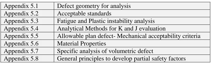
Table 1:RSE-M Appendix 5 content
Appendix 5.1 Defect geometry for analysis Appendix 5.2 Acceptable standards
Appendix 5.3 Fatigue and Plastic instability analysis Appendix 5.4 Analytical Methods for K and J evaluation
Appendix 5.5 Allowable plan defect- Mechanical acceptability criteria Appendix 5.6 Material Properties
Appendix 5.7 Specific analysis of volumetric defect
BASIC APPROACH FOR FLAW EVALUATION
General
The step by step flaw evaluation procedure is based on:
‐ Elastic stress evaluation of the component (based on an un-cracked model) to determine stress on the cracked section,
‐ Elastic stress intensity KI, KII and KIII evaluation through superposition principle (influence functions), associated to a combination rule for mode I, II and III
‐ J evaluation scheme based on reference stress method, considering in particular different approaches for mechanical and thermal loads
‐ Comparison with allowable maximum load for the cracked body to analyze margins in front of collapse load with consistent margins as the design rules
‐ Comparison of J evaluation with the material J-resistance curve proposed in RSE-M appendices 5.6 Different improvements are done in a case by case basis:
‐ cladded components
‐ J-estimation scheme by reference stress method, with specific considerations:
o Mechanical and thermal loads
o Ferritic steels with "plateau" on stress-strain curve
o Weld mismatch ‐ Steam Generator tube
This paper will be focused on different Jpl estimation scheme, considering plasticity and elastic stress classification.
Elastic stress intensity factors
‐ Basic principle of the stress intensity factor evaluation:
o Polynomial stress distribution in the cracked section:
= 0 + 1 x/t + 2 (x/t) 2 + 3 (x/t) 3 + 4 (x/t) 4
o Use of a large data bank of influence function i to derive K value:
The RSE-M K handbook of influence functions
Content of the K handbook of power 4 influence functions: ‐ for cylinder (and plate), for:
o a/t = 0 ; 0.1 ; 0.2 ; 0.4 ; 0.6 ; 0.8
o a/c = 1 ; 1/2 ; 1/4 ; 1/8 ; 1/16 ; 0 (a/c = 0 infinitely long crack)
o t/ri = 1; 1/2; 1/5; 1/10; 1/20; 1/40; 1/80; 0 (t/ri = 0 plate of infinite radius)
o surface point and deepest point, inner surface and outer surface crack ‐ plate, cylinder, elbow, thickness variation
‐ around 80 tables to cover all these geometries:
o plate, cylinder, thickness variation, elbow
o with different cracks: elliptical and infinite crack, surface and sub-surface, inner and outer surface.
J evaluation scheme based on reference stress method
Basic principle of the reference stress method: ‐ Js = Jpl
‐ Jpl / Jel = ref / (ref/E) = 1/KR ‐ ref = LR . y = C /CL,y . y
‐ ref correspond to ref on the stress strain curve
4 4 4 3 3 3 2 2 2 1 1 00i i xt i xt i xt i xt
‐ Js = Jpl = Jel [ ref / (ref/E) + ] with = 0.5 [ref2 /(ref2 + y2)]Two ways for application: ‐ Failure assessment Diagram: one by stress-strain curve
‐ Numerical approach of Jpl
Data collection for J estimation - Geometry and sizes
- Crack size and location: 2a – 2l - Applied Loads: C
- Material properties: base metal and weld
o Stress-strain curve
o Young modulus
o Toughness
‐ Limit load formulae and K influence functions for the geometry and the crack to consider Step by Step numerical J estimation scheme
‐ Step 1: Elastic K and J evaluation
o Elastic stress evaluation of un-cracked component
o Stress in the crack section polynomial smoothing of order 4
= 0 + 1 x/t + 2 (x/t) 2 + 3 (x/t) 3 + 4 (x/t) 4
o Using RSE-M K Handbook for given geometry and crack
o Jel = K2 / E ‐ Step 2: CL evaluation
o Limit load of cracked component for typical load for y flow stress
o Using Compendium ‐ Step 3: LR = C / CL ‐ Step 4: ref = LR Rp0.2
‐ Step 5: ref on stress-strain curve for ref ‐ Step 6: KR estimation
KR = [ ref / (ref/E) + ] with: = 0.5 [ref2 /(ref2 + Rp0.2 2)]
‐ Step 7: Js = Jpl = Jel / KR2
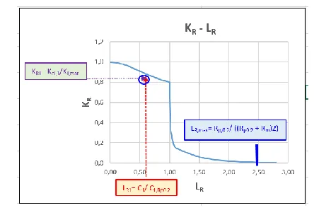
Graphical presentation of Failure Assessment Diagram ‐ Step 1: ref evaluation
o for LR = 0 to (Rp0.2 + Rm)/Rp0.2 , evaluate ref = LR Rp0.2 ‐ Step 2: ref on stress-strain curve for ref
‐ Step 3: KR estimation
Figure 1: Kr – Lr Failure Assessment Diagram
‐ Step 5: Use of Failure Assessment Diagram (FAD)
o Evaluate LR1 for a load C1: LR1 = C1 / CL,RP0.2
o Evaluate elastic Kel,1 for load C1 with influence function
o Evaluate KR1 for load C1 and material toughness KJ: KR1 = Kel,1 / KJ ‐ Step 6: Evaluation of intersection point:
o Under the FAD : no crack initiation for C1
o Over the FAD: crack initiation and ductile crack growth has to be evaluated J EVALUATION SCHEME IMPROVEMENTS
“Mismatch Effect” on J evaluation for Mechanical Loads in a weld
Scope of validity
The proposed method is valid for: ‐ a straight pipe,
‐ a V-shaped, circumferential weld joint, which involves two materials and is "overmatched" (i.e. where the weld deposited metal has a higher yield stress than the base metal),
‐ identical elastic properties for the base metal and the crack weld deposited metal,
‐ a mechanical load such as internal pressure, axial load and/or bending moment / torsional moment, ‐ an axisymmetric or semi-elliptical emerging defect with a relative depth of a/t < 0.25
‐ a circumferential defect on the internal surface at the centre of the joint (see Figure 2 - position 1), ‐ a circumferential defect on the internal surface at the base of the weld bead (see Fig. 2 position 2), ‐ a circumferential defect on the external surface at the base of the weld bead (see Fig. 2 position 3),
with the crack tip on the base metal side,
‐ a defect on the internal surface at the interface between the base metal and the weld deposited metal (see Fig.2 position 4)
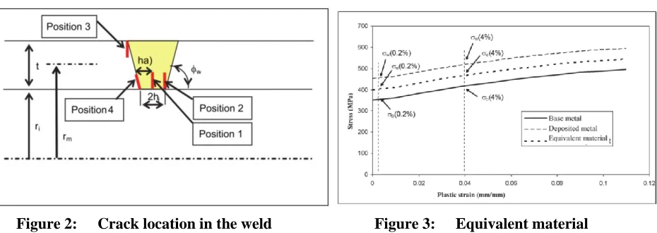
Definition of Equivalent Material
The definition of equivalent material is based on a law governing mixtures which covers the stress-strain curves for the base metal and the weld deposited metal (Figure 3). For a given plastic strain, the
Figure 2: Crack location in the weld Figure 3: Equivalent material
Where:
‐ b is the stress corresponding to plastic strain p on the stress-strain curve for the base metal,
w is the stress corresponding to plastic strain p on the stress-strain curve for the weld deposited metal,
‐ M is the “local” mismatch associated with plastic strainp, corresponding to the ratio w / b, ‐ (M) is the weight function which depends on the geometric data for the problem (defect and
component part) and the mechanical load to consider
With low levels of plastic strain (less than 0.006 mm/mm), this curve must be corrected to allow for a gradual progression between the stress-strain curve for the base metal and that of the equivalent material. This correction is carried out on the basis of the following relation which is applied to parameter when creating the stress-strain curve for the equivalent material:
Similar formulae are proposed in RSE-M Appendix 5.4 for thickness transition and elbow with circumferential and longitudinal surface crack
Mechanical Imposed Displacement load
J evaluation for imposed displacements using simplified methods is complex because of the relationship between the global imposed load and the actual stresses imposed at a potential crack: unlike with imposed force type loadings, evaluating the stresses, and in particular the reference stress, is no longer merely a geometric relation linked to the structure and the defect but also has to take account of the material stress-strain curve. The detailed are presented in RSEM-Appendix 5.4 Article IV.6 (not presented in this paper) Thermal loads (without mechanical load)
Scope and validity limits
The scope of validity for the Jth method is as follows:
‐ straight pipe or shell such as rm/t 3 only subject to a thermal cooling transient applied to an internal surface;
‐ any RCC-M material or similar;
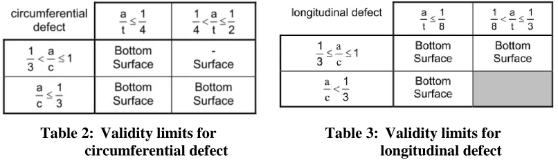
‐ circumferential or longitudinal defect located on a straight cylindrical section well away from any major discontinuity:
o more than or equal to from a thickness transition, from an elbow.
o and located more than or equal to from an elbow.
Table 2: Validity limits for circumferential defect
Table 3: Validity limits for longitudinal defect
The validity limits of Jth for Thickness transition and elbows is defined in RSE-M Appendix 5.4 article V.1.
Jth General Expression
Radial temperature variations in the wall due to thermal transients lead to imposed strains, consequently, Jel shall be corrected to allow for attenuation due to plasticity effects.
Jth = k2th . Jelth where:
‐ Jelth: maximum value of J elastic during the transient ‐ kth: elastic-plastic adjustment coefficient
‐ Jel: elastic J obtained by J KI2 / E* with KI the elastic stress intensity factor
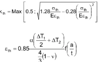
Kth evaluation: Option 1 without stress-strain curve
with adimensional parameter Lth:
‐ T1 and T2 are values for T1(tps) and T2(tps) recorded at the time during the thermal transient when Jelth is maximum
‐ S0 is the stress obtained over the material’s stress-strain curve for which elastic strain is equal to plastic strain (S0 may be determined by considering the intersection between the stress-strain curve and the straight line for equation 0.5 E
‐ : linear expansion coefficient for the material;
‐ f: coefficient obtained by linear interpolation as a/t from Table 2 for a circumferential defect and from Table 3 for a longitudinal defect;
Table 4:f values for a circumferential defect Table 5:f values for a longitudinal defect
Kth evaluation: Option 2 using stress-strain curve
The elastic-plastic correction factor kth is defined by:
with strain th:
‐ T1 and T2 are values for T1(tps) and T2(tps) taken at the time during the thermal transient when Jelth is at its maximum
‐ th is the stress corresponding to strain th for the material’s true stress-strain curve ‐ is the linear expansion coefficient for the material
‐ f is calculated as in option 1 (Tables 2 and 3)
‐ the characteristics of the material and th = f(th) are taken at the final fluid temperature Tf
J under combined mechanical and thermal load
General evaluation
The effect of radial temperature variations in the wall thickness due to thermal transients referred to as "th" is processed separately before being combined, multiplied by coefficient kth*, with that due to other mechanical and thermal loads referred to as "mt".
According to the chosen method, Kcp or Js , in order to calculate an estimate of J under mechanical and thermal loads other than a thermal transient, the value of J under a combined load is given by the following formulae:
J – Calculation of kth* for Straight Pipe
‐ for circumferential surface crack
kth* is evaluated as:
o If at least one of the following two conditions a) and b) is verified: a) Lr 0.5
b) Lr(P=0) 2p
where p relates to reduced pressure (RSE-M Appendix 5.4 Article IV.4.1.1.1) then: kth* kth
o Otherwise:
‐ For longitudinal surface crack
o Kth* = kth
J- Calculation of kth* for Thickness Transition and Elbow
‐ Similar formulae are proposed in RSE-M Appendix 5.4 for thickness transition and elbow with circumferential and longitudinal surface crack
CONCLUSION
Since 1990 the RSE-M In-service Code is regularly updated, in particular for flaw evaluation rules. The last Edition published is 2016 and will be used by a lot of PWR plants in the world (around 100 in a near future). This RSE-M appendix 5 on "flaw evaluation" is developed in total consistency with RCC-MRx Appendix A16.
The key innovative approach of RSE-M flaw evaluation are:
‐ an innovative new approach for defect/defect interaction and defect/surface interaction
‐ an extensive Handbook (around 80 tables) of order 4 influence function for straight pipe, thickness transition and elbow in order to evaluate elastic K
‐ associated to elastic K evaluation, multi-modal loads and equivalent Keq formulae is provided ‐ plastic zone size correction for limited plasticity, slightly more than small scale yielding with
dedicated and coefficients ‐ cracks close and in the cladding
‐ a J estimation scheme based on reference stress
‐ a large set of limit loads formulae's for cracked straight pipe, thickness transition and elbow
‐ different J estimation scheme improvements: weld mismatch, mechanical displacement control load, thermal loads, mixed thermal and mechanical loads
‐ fatigue crack growth analyses with conservative da/dN-K laws, mixed mode condition, plasticity correction and transient combination rules
‐ plastic collapse loads of cracked components ‐ all the material properties needed for analyses
‐ partial safety factors on loads and toughness, considering also uncertainties in crack size and location
‐ recently, "Warm Pre-Stress" considerations for cladded Reactor Pressure Vessel was added in a non-mandatory Code Case.
‐ recommendation to add a detailed finite element analyses of cracked components for the more limited case
A large validation program has been developed with a large number of comparisons of J estimation through RSE-M engineering methods and direct finite element analysis of cracked body. All the quality assessment associated to these rule development is a key issue to assure safety and availability of French and International Nuclear PWRs.
ACKNOWLEDGEMENTS
The author thanks all partners of RSE-M Sub-committee and Working Group on flaw evaluation for their long investment in this "flaw evaluation" engineering methods: Ph. Geyer (EDF), B. Barthelet (EDF), E. Meister (EDF), Ph. Gilles (AREVA), P. Le Delliou (EDF), M.H Lacire (CEA), S. Kayser (CEA)
REFERENCES
RSE-M Code, "Rules for In-service Inspection of Nuclear Power Plant Components", AFCEN RSE-M 2016 Edition
RCC-MRx Design and Construction Rules for Mechanical Components, AFCEN RCC-MRx 2015 Edition."RCC-M - Design and Construction Rules for Mechanical Components,of PWR Nuclear Island", AFCEN RCC-M 2016 Edition
P. Le Delliou, B. Barthelet, P. Cambefort, “RSE-M Code Progress regarding Flaw Assessment Methods and Flaw Acceptance Criteria”, International Conference on Nuclear Engineering, ICONE 8, paper ICONE-8307, Baltimore, USA, April 2000.
Barthelet, B., et al., "RSE-M Code progress in the field of examination evaluation and flaw acceptance criteria", SMIRT 13 Conference, Vol. II, pp. 647-652, Stuttgart, Germany, August 1995
C. Faidy, B. Barthelet, B. Drubay, "Status of French Flaw Evaluation Procedures", ASME Pressure Vessel and Piping Conference, Vol. 332, Montreal, Canada, July 1996.
Faidy C., "Recent Changes in French Regulation and Codes for Nuclear and Non-Nuclear Pressure Equipments" ”, International Conference on Nuclear Engineering, ICONE 8, paper ICONE-8636, Baltimore, USA, April 2000.
Chapuliot, S., et al., 1998, "Stress intensity factors for internal circumferential cracks in tubes over a wide range of radius over thickness ratios", ASME Pressure Vessel and Piping Conference, Vol. 365, pp. 95-106
Chapuliot, S., and Lacire, M.H., 1999, "Stress intensity factors for external circumferential cracks in tubes over a wide range of radius over thickness ratios", ASME Pressure Vessel and Piping Conference, Vol. 388, pp. 3-12
R.A. Ainsworth, "The Assessment of Defects in Structures of Strain Hardening Material", Engineering Fracture Mechanics, Vol.19, No. 4, pp. 633-642, 1984
Barthelet, B., and Valeta, M.P., "Elastic plastic fracture analysis of elliptical circumferential surface flaws in cylinders under pressure and bending", SMIRT 14 Conference, Vol. 4, pp. 135-142, Lyon, France, August 1997.
Papin, M.H., et al, "Evaluation of J on a pipe subjected to mechanical and thermal loading", SMIRT 14 Conference, Vol. 4, pp. 127-134, 1997.
AFCEN, "Règles de conception et de construction des matériels mécaniques des îlots nucléaires PWR.", Barthelet, B., and Faure, F., "Material properties for in-service inspection RSE-M Code flaw evaluation",
SMIRT 15 Conference, Vol. III, pp. 135-142, Seoul, KOREA, 1999.
Ardillon, E., Barthelet, B., and Sørensen, J., "Probabilistic calibration of safety factors for nuclear operating installations", ASME Pressure Vessel and Piping Conference, Vol. 375, 1998.
RCC-MRx Code 2010 for Sodium Reactor (SFR), Research Reactor (RR) and Fusion (ITER) : General Overview and CEN -Workshop", paper PVP2011-57614, ASME 2011 Pressure Vessels & Piping Division Conference, PVP2011, July 17-21, 2011, Baltimore, Maryland, USA.
Marie, S., Chapuliot, S., Kayser, Y., Lacire, M.H., Drubay, B,. Barthelet, B., Le Delliou, P., Rougier, V., Naudin, C., Gilles, P. and Triay, M., 2007, "Flaw analysis in the French RSE-M and RCC-MR Code. Presentation of the fracture parameters calculation – Part I: General overview, Part II: Cracked plates", International Journal of Pressure Vessels and Piping, Vol. 84, pp.590-613. S. Marie, S. Chapuliot, Y. Kayser, MH. Lacire, B. Drubay, B. Barthelet, P. Le-Delliou, V. Rougier, C.
Naudin, P. Gilles, M. Triay, "French RSE-M and RCC-MR code appendixes for flaw analysis: presentation of of the fracture parameters calculation- Part III : cracked pipes", International Journal of Pressure Vessel and Piping 84, p. 614-658, May 2007.
S. Marie, S. Chapuliot, Y. Kaiser, MH Lacire, B. Drubay, B. Barthelet, P. Le-Delliou, V. Rougier, C. Naudin, P. Gilles, M. Triay, "French RSE-M and RCC-MR Code Appendices for Flaw Analysis : Presentation of the Fracture Parameters Calculation – Part IV Cracked Elbow", International Journal of Pressure Vessel and Piping 84, p. 659-686, May 2007.
S. Marie, S. Chapuliot, Y. Kayser, MH. Lacire, B. Drubay, B. Barthelet, P. Le-Delliou, V. Rougier, C. Naudin, P. Gilles, M. Triay, "French RSE-M and RCC-MR code appendixes for flaw analysis: presentation of the fracture parameters calculation- Part V : elements of validation", International Journal of Pressure Vessel and Piping 84, p. 687-696, May 2007.
C. Faidy, " Flaw Evaluation in Elbows Through French RSE-M Code", ASME Pressure Vessel & Piping Conference, paper PVP2010-25085, Bellevue, Washington, USA, July 2010
C. Faidy, "Comparison of French RSEM and ASME BPVC Section XI Fatigue Crack Growth Analysis", ASME Pressure Vessel & Piping Conference, PVP2014-28547, Anaheim, USA, July 2014 P. Le-Delliou, S. Chapuliot, "Comparison of the Stress Intensity Factor Influence Coefficients for Axial
ID Surface Cracks In Cylinders of RSE-M and API 579-1", ASME Pressure Vessel & Piping Conference, PVP2015-45236, Boston, USA, July 2015
C. Faidy, "Stress Intensity Factor Handbook- Comparison of RSEM and ASME XI Codes", ASME Pressure Vessel & Piping Conference, PVP2015-45199, Boston, USA, July 2015
D. Moinereau & al., "Inclusion of Warm Pre-Stress Concept in French RPV Structural Integrity Assessment", ASME Pressure Vessel & Piping Conference, paper PVP2016-63114, Vancouver, Canada, July 2016,