Shielding Analysis and Dose Rate Evaluation for the I&C System Development of
an Instrumented Fuel Capsule
Young-Hwan KANG 1), Dong-Soo Lee2), Chang-Je Park1), Bong-Goo KIM 1), and Hark-Rho KIM1)
1) Korea Atomic Energy Research Institute, P.O. Box 105, Yusong, Daejeon, 305-600, Korea [email protected] 2) National Fusion Research Center, 52 Eureun-Dong,Daejeon, Korea
ABSTRACT
A new I&C system for an irradiation test of advanced PWR fuels in the HANARO reactor was designed and manufactured to provide more accurate data to a fuel and material developer. The fuel irradiation tests will be carried out in the OR hole of HANARO with a thermal flux level of ~ 4 x 10¹⁴ n/cm2.s for 4 cycles. The characteristics of UO
2 fuel rods with cladding breaches that were developed from literature and laboratory test data were applied to review a potential safety hazard of the new irradiation system through a shielding analysis and dose rate evaluation. The total fission products generated from the three test fuel rods were analyzed by the ORIGEN-2.0 computer code. The shielding calculations were performed by using the computer code Microshield 6.20. From the analysis, the maximum equivalent dose at specific locations, where a high radioactivity is expected, was less than the permitted dose rate of 6.25 μSv/h in the normal working areas of HANARO, which was 3.74 μSv/h. But the equivalent dose in the delay tank was 185.9 μSv/h which is 30 times greater than the regulation permits. Therefore, shielding in the gas flow tube line is not required but an adequate shielding by the installation of a lead wall with a 20.5 cm thickness, on the other hand, is required in the delay tank zone of an I&C system.
KEY WORDS: HANARO, Capsule, I&C System, Nuclear Fuel, Shielding, Dose Rate
INTRODUCTION
HANARO (High-flux Advanced Neutron Application Reactor) is one of the many large scale national research facilities in Korea. It offers various types of irradiation tests for fuel and materials, which provides us with very useful information for designing and evaluating advanced reactor materials for the development of a next generating nuclear plant and other Generation IV systems.
An in-pile test program for the development of a high burn-up fuel is planned for the HANARO reactor. For the fuel irradiation tests, an I&C system recently developed at KAERI and an instrumented capsule with a double-cladded concept will be used. Three test fuel pins with 5 UO2 pellets each are being loaded into the capsule [1]. It is well known that a small percentage of the fuel cladding has been breached due to a corrosion or mechanical damage [2]. If a fuel failure occurs in the system during an irradiation, radioactive gaseous fission products retained in the test fuel pins will be successively released to the annulus gap between the fuel cladding and the mini-capsule tube, the gas flow tube and finally a decay vessel of the I&C system (GSF-2002) [3]. Such a possible release from a potential failure scenario could affect the safety as well as the health of the reactor workers. For this reason, a series of analyses was implemented to understand the total fission gas release behavior from the expected failed fuel pins and to characterize the risk posed by radioactive sources at the HANARO reactor in the event of a breach of test fuels.
ANALYSIS AND DISCUSSION
Radionuclide Determination from Test Fuels
The test fuel to be selected is short rods of Zr-4 clad UO2 pellets of an advanced PWR 17x17design [4]. The irradiation at the HANARO reactor will be performed for a total of 4 cycles (one cycle lasts for 21 days with 30 MWt). The burnup of the above fuel is estimated to be around 6 GWd/Mtu, which was confirmed by the PIE data obtained from the gamma scanning method [5].
The input and assumptions for the fuels irradiated in the commercial power plant are not, in general, applicable to the fuels irradiated in the research reactor. However, a trend of the produced nuclides can be of benefit in evaluating various aspects of a fuel performance. Before the application of the ORIGEN2.0 code [6] to the HANARO reactor study, the radioactivity of the total fission products within the UO2 fuel rod plenum, released from PWR fuels withdrawn at a burnup of 41.8 and 55 GWd/Mtu as given in Table 1, are calculated via the ORIGEN 2.0 code. Especially the Kr-85 radioactivity calculated by the code, which is a reliable marker of a fission gas release, was compared with the PIE data [7] which was obtained from an accurate radiochemical measurement of the Kr-85 in the gas collected from the plenum of commercial fuel elements. The difference between each calculated and measured data as given in Table 2 have very similar levels of agreement, indicating that the code works quite well over a wide range of burn-ups.
Table 1. Fuel Characteristic of Young Kwang Unit 1 and Kori Unit 2
Fuel Young Kwang Unit 1 Kori Unit 2
Enrichments (%) 4.201 3.80
Total length of fuel (mm) 3865.9 3844.5
Total weight of UO2(kg) 1.976 1.977
Total Calculated burn-up (GWd/Mtu) 55.1 41.8 Release amount of total fission gases(cc) 228.5 10.5 Release amount of Kr-85 gas(cc : assumed) 1.4 0.064
Table 2. Comparison of the measured and calculated Kr-85 radioactivity
Fuel for Plant Site(GWd/Mtu) Measured Average Data (Ci) Calculated Data by ORIGEN-code (Ci)
Young Kwang Unit 1 (55) 2.00 1.69
Kori Unit 2 (41.8) 0.0915 0.093
The total fission products produced in the above test fuel pellets to be irradiated in the HANARO reactor were analyzed by the ORIGEN-2 computer code. During a normal operation to a burnup of 6 GWd/Mtu, the concentration of the fission products in the fuel matrix gradually increased and around 700 fission products were produced. Most of the fission products generated are generally expected to be located inside a fuel matrix and only a few percent of the total products produced from fission could be released to the plenum of the fuel pin.
As the coolant temperature of the HANARO reactor is 40 ºC and the surface temperature of the internal fuel cladding is around 200±20 ºC, a few fractions of the inventory of the fission gases and some of the more volatile radio-elements (e.g. krypton, xenon, cesium and iodine) could be released and accumulated in the plenum of the test rod during an in-reactor operation. Furthermore, even during a reactor accident, most of the cesium exists as CsI and CsOH and the vaporization rate of CsI is increased only at the temperatures above 500 ºC [9-11]. Thus, when the cladding is breached, 3 of the 19 radio-elements such as krypton, xenon, and iodine are selected for the analysis.
Determination of R/B and Leakage
It is generally known that the fractional release rate is dependent upon the atmosphere, fuel burn-up, temperature, and fuel composition [8]. The release to birth ratio(R/B) of the gaseous fission products of the fuel in this study was evaluated based on the measured data by C.A. Friskney and J.A. Turnbull [12] and with ANS 5.4 model predictions [13]. Friskney measured the release rates for the unstable rare gases of Kr-88, Kr-87, Kr-87m, Xe-133, Xe-135, and Xe-138 for samples of polycrystalline and large-grained uranium di-oxide with a burnup of 6407 MWd/Mtu in the temperature range 700-1550 °C. Figure 1 shows the fractional release of the gaseous fission products with the decay times from Friskney’s experiment with ANS 5.4 model predictions. The measured frictional releases are generally slightly smaller than the results based on the ANS 5.4 model. This trend matches the data calculated from B.J. Lewis well [14].
One of the most important key parameters is a leakage rate to determine the magnitude and composition of the released fission products as radioactive sources which depends on the size of a breach and the number of breached fuel rods in a capsule. If a fuel failure is monitored in an experimental system during an irradiation, the radioactive gaseous products will be collected in a delay tank within one minute which was evaluated based on our experimental system characteristics [15]. The leakage rate was derived from the measured radioactivity concentration in the coolant of the PLUTO reactor which was reported by J.D. Page [16] as given in Table 3. Krypton, xenon and iodine elements show a high leakage rate in the order of 3%/10min or more.
Figure 1. Comparison of the measured data from Friskney’s experiment with ANS 5.4 model predictions
Equivalent Dose Calculation and Shielding Analysis
The mixed gaseous fission product sources from the three fuel pins by the ORIGEN 2.0 code were obtained by using the uranium mass, a burn-up, R/B ratio, and leakage rates of the gaseous fission products determined from the above sections. The boundary condition of an irradiated fuel for the analysis is shown in Table 4. From the source evaluation, since the gaseous fission products are more likely to be released in the event of a breach of a test fuel pin, the noble gases (Xe, Kr) and volatile fission products (I) are of most concern. Table 5 shows the three different radio-elements with a high gamma energy which were released from the test fuel pins for 1 minute after a cladding failure.
Table 3. Fission gas leakage from the fuel pin [16]
Nuclides Leakage
(%/10min.) Nuclides
Leakage (%/10min.)
Kr-83m 3 Xe-135m 11
Kr-85m <1 I-131 3 Kr-88 14 I-132 3
Xe-131 ~ I-133 13
Xe-133 ~ I-134 3
Xe-133m ~ I-135 5
Xe-135 10
The computer program Micro-shield 6.2 [17] was used to calculate the doses from specific locations as shown in Figure 2. A final calculation of the source term in the analysis also includes several levels of conservatism to obtain a conservative source term.
1) The linear power used was 425 W/cm which is equivalent to 1.15 times that of the normal power calculated by using the COSMOS code from the HANARO Neutron Physics Group.
2) R/B ratios were determined based on the ANS 5.4 model.
3) As can be seen in Table 3, even though different nuclides have different leakage rates from the fuel, 20 %/10min of the leakage rate was used for the analysis to obtain a more conservative result.
4) In addition, a large breach of three fuel pins is assumed to occur simultaneously and all the gaseous fission products accumulated in the plenum are also released to the gas flow tubes and the decay tank.
Table 4. Boundary conditions of the irradiated fuel characteristics
Irradiation Time(day) 92.0 Average Linear Power(W/cm) 426.8
Burn-Up(MWD/MtU) 8058.8 Average Fuel Temperature(°C) 800.0
Gas Flow Rate(cc/min) 50.0 Flow Tube Diameter (inch) 0.4 Total Length of the Flow Tube (m) 23.0
Table 5. Fission gas leakage from the fuel pins for 1 minute
Nuclides 4 Cycle-burned
Fuel Activity(Ci) R/B Ratio
Activity in Fuel Plenum(Ci)
Leakage Ratio (%/min)
Total Activity for 1 min.(Ci)
Kr-83M 2.53E+01 7.51E-03 1.90E-01 3.80E-03
Kr-85M 5.81E+01 1.16E-02 6.75E-01 1.35E-02
Kr-85 2.19E-01 1.51E-01 3.29E-02 6.59E-04
Kr-87 1.16E+02 6.20E-03 7.18E-01 1.44E-02
Kr-88 1.64E+02 9.22E-03 1.51E+00 3.02E-02
I-131 1.44E+02 7.47E-02 1.08E+01 2.16E-01
I-132 2.27E+02 8.32E-03 1.89E+00 3.77E-02
I-133 3.41E+02 2.50E-02 8.50E+00 1.70E-01
I-134 3.80E+02 5.16E-03 1.96E+00 3.92E-02
I-135 3.17E+02 1.80E-03 5.70E-01 1.14E-02
Xe-131M 1.41E+00 8.90E-02 1.26E-01 2.51E-03
Xe-133M 1.02E+01 3.99E-02 4.07E-01 8.14E-03
Xe-133 3.19E+02 6.09E-02 1.94E+01 3.88E-01
Xe-135 7.90E+01 1.66E-02 1.31E+00
0.02
2.63E-02
The maximum equivalent dose at 1m from the specific locations, where a high radioactivity is expected, is 3.74 μSv/h which is much less than the permitted dose rate of 6.25 μSv/h in the normal working area of HANARO from
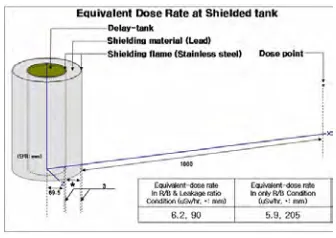
existing facilities. But the equivalent dose in the delay tank is 185.9 μSv/h which is 30 times greater than the regulation permits. The required thickness of a shielding depends on the quality of the radiation, radioactive sources being produced at a certain chosen period of time, and the material of which the barrier is to be constructed. Lead is generally used as a shielding material in the irradiation facilities of HANARO. From the results, a shielding in the gas flow tube zone is not required, but a gas flow tube, which will be inserted into the stainless steel 304 tubes, will be installed in HANARO to prevent mechanical damage and to maintain the improved working atmosphere and safety. Adequate shielding by a heavy metal Pb, on the other hand, is required for the delay tank zone as shown in Figure 3. For the case of a large breach of three fuel pins, a maximum of 20.5 cm in thickness of lead is recommended to reduce the dose rate in the delay tank zone.
Figure 2. Location of the gas flow lines being installed in the HANARO reactor
Figure 3. Equivalent dose calculated at the delay tank after shielding CONCLUSIONS
From the shielding analysis and dose rate evaluation posed by radioactive sources at the HANARO reactor in the event of a breach of test fuels, the following results have been obtained:
- Accurate evaluation of the mixed sources for the new irradiation experimental system in the HANARO reactor was found to be difficult. However, several key parameters such as the R/B ratio and leakage rate, which were determined based on the data collected from a literature survey, were enough to calculate the produced gaseous fission products by using the ORIGEN 2.0 code and to conservatively characterize the risk posed by radioactive sources.
- The equivalent dose rates from the sources in the working areas were less than that of the allowable HANARO limit (6.25μSv/hr) for the people who work in the research reactor.
- Based on this, no additional shielding is required, however, access to the area of a decay vessel may need to be limited, and the installation of a Pb wall with a 20.5 cm thickness is recommended.
This data will be used for a licensing of the I&C System (GSF-2002).
Acknowledgement
This project has been carried out under the Nuclear R&D Program by MOST (Minister of Science and Technology). The authors would like to express their appreciation to the Ministry of Science Technology (MOST) of the Republic of Korea for support of their work through the mid- and long-term Nuclear R&D Project.
1.5m
1.6m
3.4m
4.6m 1m
3.8m
3.5m
3.6m
작업자A
3m
4m 1m
5m
가상의
작업자B
REFERENCES
1. Kang, Y.H., Kim, B.G., Cho, M.S., Choo, K.N., Kim, Y.J., “Current status and the future of the irradiation services in the HANARO reactor, Proc. of 2004 ANES, 27-28, Miami Beach, Florida U.S.A. October 3-6, 2004.
2. Ware, A.G., “Mechanical damage experience in major light water reactor systems” CONF-900617-12 3. Y.H. Kang, S.J. Park, et al., “Introduction of the I&C system for the fuel irradiation tests”, Proc. of the Korean
Nuclear Society Spring Meeting, JeJu Ramada Hotel, Korea, May 26-27 2005
4. Y.H. Kang, et al., “Research reactor utilization technology development”, KAERI/RR-2360/2003, KAERI 5. H.M. Kim,, Private Communication(2005)
6. ORIGEN 2.0, ORNL, Oak Ridge, Tennessee. August 1996. 7. D.G. Min, Private Communication(2006)
8. J. Rest and A.W. Cronenberg, “Modeling the behavior of Xe, I, Cs, Te, Ba, and Sr in solid and liquefied fuel during severe accidents”, J. Nuclear Materials, 150(1987) 203-225.
9. H. J. Teague, A generic overview of severe accident phenomena, fission product transport processes in reactor accidents (1990)9, edited by J.T. Rogers, Hemisphere Publishing, 79 Madison Avenue, New York, NY 10016 (USA) 10. Ari Auvinen, et al., “Vaporization rates of CsOH and CsI in conditions simulating a severe nuclear accidents”, J.
Aerosol Sci. 31, No. 9(2000) 1029~1043
11. C. E. L. Hunt, F. C. Iglesias and D. S. Cox, “Measured release kinetics of iodine and cesium from UO2 at high temperature under reactor accident condition, fission product transport processes in reactor accidents”, (1990)168, edited by J.T. Rogers, Hemisphere Publishing, 79 Madison Avenue, New York, NY 10016 (USA)
12. C.A. Friskney and J.A. Turnbull, J. Nuclear Materials, 79(1979) 184-198.
13. W. N. Rausch, F. E. Panisko, ANS-5.4: A computer subroutine for predicting fission gas release, NUREG/CR-1213 PNL-3077, 1979
14. B. J. Lewis, Source term of iodine and noble gas fission products in the fuel-to-sheath gap of intact operating nuclear fuel elements, J. Nuclear Material, 172(1990)197-205
15. D.S. Lee, Y.H. Kang, B.G. Kim, et al., The shielding analysis for the I&C system (GSF-2002) development of an instrumented fuel capsule”, KAERI/TR-3240/2006 (2006)
16. J.D page, RWE Solutions, KIFC/DN03, MD31481 (2001) 1-11.
17. Micro-shield V6.20, Grove Software, Inc. 147 Mill Ridge Road Lynchburg, VA 24502 (2005)

![Figure 2. A final calculation of the source term in the analysis also includes several levels of conservatism to obtain a The computer program Micro-shield 6.2 [17] was used to calculate the doses from specific locations as shown in conservative source te](https://thumb-us.123doks.com/thumbv2/123dok_us/1700045.1215515/3.612.137.478.517.677/calculation-analysis-includes-conservatism-computer-calculate-locations-conservative.webp)