Experimental Implementation of a Nonlinear Control Method for
Magnetostrictive Transducers
William S. Oates, Phillip Evans, Ralph C. Smith and Marcelo J. Dapino
Abstract— In this paper, we discuss the development and experimental implementation of a nonlinear control design for magnetostrictive transducers operating in hysteretic regimes. The hysteresis and constitutive nonlinearities are characterized using a homogenized energy framework based on energy relations at the lattice level employed in combination with stochastic homogenization techniques that incorporate material and field nonhomogeneities. Using this framework, we employ nonlinear optimal control theory to construct open loop inputs for tracking. We subsequently employ PI-based perturbation feedback to ensure robustness with respect to model uncer-tainty and sensor noise. Experimental implementation results at frequencies up to 1000 Hz demonstrate the feasibility of the method for high speed tracking while operating in highly nonlinear operating regimes.
I. INTRODUCTION
Present and emerging automotive, industrial, aeronautic, aerospace and biomedical applications require actuators that provide large force, high accuracy, moderate stroke, broad-band capabilities. Moreover, the actuators often must be compact, reconfigurable and multifunctional. For a num-ber of applications, transducers employing ferroelectric or ferromagnetic drive elements meet these criteria and are being considered for high performance control systems. Two common ferroelectric and ferromagnetic actuator materials are lead zirconate titanate (PZT) and Terfenol-D.
Whereas these compounds provide unique actuator capa-bilities, they also exhibit hysteresis and constitutive nonlin-earities that must be accommodated in models, transducer designs, and model-based control designs to achieve strin-gent tracking and control specifications. The fact that the hysteresis and nonlinearities are rate, stress, and temperature-dependent compound the challenge of high performance actuator design.
The most obvious way to limit hysteresis and nonlinear effects is to restrict devices to low or moderate drive regimes. Whereas this is feasible for some applications, it excludes the devices from many high performance applications where can prove advantageous over traditional actuators. Secondly,
This research was supported in part by the Air Force Office of Scientific Research under the grant AFOSR-FA9550-04-1-0203.
William S. Oates is with the Department of Mechanical Engineer-ing, Florida State University, Tallahassee, FL 32306 (USA) (email: [email protected]).
Phillip Evans is with the Department of Mechanical Engineering, The Ohio State University, Columbus, OH 43210 (USA) (email: [email protected]).
Ralph C. Smith is with the Department of Mathematics, North Carolina State University, Raleigh, NC 27695 (USA) (email: [email protected]). Marcelo J. Dapino is with the Department of Mechanical Engineer-ing, The Ohio State University, Columbus, OH 43210 (USA) (email: [email protected]).
feedback can be used to linearize the material behavior for certain operating regimes. However, it is illustrated in [9] and Section IV that the authority of feedback algorithms degrades at high frequencies. PZT-based devices can also be linearized to a certain degree through the use of current or charge-controlled amplifiers [6], [7]. However, this can prove expen-sive when compared with more traditional voltage-controlled amplifiers, and current-control is ineffective for maintaining a fixed dc bias as required for various applications — e.g., maintaining a fixed position with anx-stage while sweeping with a y-stage in an atomic force microscope.
In this paper, we experimentally demonstrate the feasi-bility of a nonlinear control design for high speed, high accuracy tracking. For brevity, we focus on a magnetic device but the models and model-based control design are equally applicable to ferroelectric materials — e.g., PZT-based devices. The tracking application is motivated by recent investigations focused on the use of Terfenol-D trans-ducers to mill automotive components at high speed while maintaining micron-level tolerances; however, the problem and general formulation are ubiquitous for a wide range of applications.
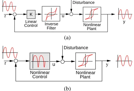
There are essentially two strategies to control hysteretic actuators using nonlinear models. The first is to use the char-acterization framework to construct an approximate nonlinear inverse that linearizes the actuator response in the manner depicted in Figure 1(a) — e.g., see [24]. Linear control algorithms are then used to achieve control objectives. This method has the advantage of linear control designs but has the disadvantage that the model inverse may be difficult to
K
r u
Disturbance
Linear
Control Inverse
Filter NonlinearPlant
y
(a)
r u y
Nonlinear Control
Disturbance
Nonlinear Plant
(b)
initiate and implement at high speed. Moreover, scaling or mapping may be required to convert amplifier outputs (e.g., voltage, current, or field) to inverse inputs (e.g., magnetiza-tion). Within the context of ferroelectric and ferromagnetic actuators, this approach has been employed using Preisach models, domain wall models and homogenized energy mod-els. We note that experimental implementation of open-loop and feedback designs employing Preisach-based inverse compensators are reported in [3], [8], [21]–[23] whereas open loop experimental control implementation of a homogenized energy inverse are reported in [4].
The second strategy is to construct nonlinear control designs which yield input signals that directly incorporate actuator nonlinearities as depicted in Figure 1(b) — e.g., see [13], [25]. If optimal control theory is employed, this approach requires the approximate solution of a two-point boundary value problem which can be computationally in-tensive. However, this technique avoids the real-time imple-mentation of the model inverse and scaling issues associated with inverse compensators.
In this paper, we demonstrate the experimental imple-mentation of a nonlinear control based on the homogenized energy framework for characterizing hysteresis in ferro-magnetic materials. Open loop control inputs are computed offline through the approximation of a two-point boundary value problem derived using optimal control theory. To provide robustness with regard to model and measurement errors, one can either linearize about the optimal state and control to construct a linear perturbation model that is amenable to LQR design, or employ direct PI feedback on measured perturbations about the optimal state. We employ the latter technique since implementation in this manner provides the efficiency of classical PI designs while ac-commodating frequency-dependent hysteresis and nonlinear material dynamics via the nonlinear open-loop signal.
The hysteresis characterization framework and transducer model are summarized in Section II. The nonlinear open loop and perturbation designs are discussed in Section III, and the experimental performance of the technique at frequencies up to 1000 Hz is illustrated in Section IV.
II. NONLINEARCONSTITUTIVERELATIONS AND
TRANSDUCERMODEL
We summarize here the ferromagnetic hysteresis frame-work developed in [16], [20] and use it to construct a model that characterizes the dynamics of the experimental magnetic transducer. As detailed in [14], [19], analogous relations quantify the hysteresis inherent to PZT and hence the framework is applicable to a range of ferroic compounds. It is noted in [4], [14], [18] that whereas the homogenized energy framework provides an energy basis for certain ex-tended Preisach models, it fundamentally differs from clas-sical Preisach models in a number of aspects including the direct incorporation of thermal relaxation mechanisms and the capability that it provides to characterize noncongruent behavior.
A. Constitutive Relations
LettingH andM denote the magnetic field and magneti-zation, we consider the lattice-level Gibbs energy relation
G(H, M) =ψ(M)−HM (1)
where the Helmholtz energy is given by
ψ(M) =
1
2η(M +MR)2 , M ≤ −MI 1
2η(M −MR)
2 , M ≥MI
1
2η(MI−MR)
M2
MI −MR
,|M|< MI. (2) Here MI, MR and η respectively denote the positive in-flection point, the local remanent magnetization, and the reciprocal slope after switching.
As detailed in [14], [16], [20], the balance ofGand the relative thermal energykT /V, wherek, TandV respectively denote Boltzmann’s constant, temperature in degrees Kelvin, and a reference volume, yields the kernel relation
M(H) =x+hM+i+x−hM−i (3)
which characterizes hysteresis at the lattice level. The frac-tionsx+andx−of positively and negatively oriented dipoles are quantified by the differential equations
˙
x+ =−p+−x++p−+x−
˙
x− =−p−+x−+p+−x+
(4)
and the expected magnetizations due to positively and neg-atively oriented moments are
hM+i= R∞
MIM e
−G(H,M)V /kTdM
R∞
MIe
−G(H,M)V /kTdM ,
hM−i=
R−MI
−∞ M e
−G(H,M)V /kTdM
R−MI
−∞ e
−G(H,M)V /kTdM .
(5)
The likelihoods of switching from positive to negative, and conversely, are given by
p+− = 1
T(T)
RMI
MI−ǫe
−G(H,M)V /kTdM
R∞
MI−ǫe
−G(H,M)V /kTdM,
p−+ =
1
T(T)
R−MI+ǫ
−MI e
−G(H,M)V /kTdM
R−MI+ǫ
−∞ e
−G(H,M)V /kTdM
(6)
where ǫ is taken to be a small positive constant. The relaxation timeT is the reciprocal of the frequency at which dipoles attempt to switch — see [14], [16], [20] for details. To incorporate the effects of polycrystallinity, material nonhomogeneities, and variable interaction fields, we assume that local coercive and interaction fields are manifestations of distributions having associated densitiesν1(Hc)andν2(HI).
This yields the macroscopic field-magnetization relation
M(H) =
Z ∞
−∞
Z ∞
0
M(H+HI;Hc)ν1(Hc)ν2(HI)dHcdHI.
For the device characterization results summarized in Sec-tion IV, values for the discretized densities were estimated using the techniques detailed in [14], [17].
B. Transducer Model
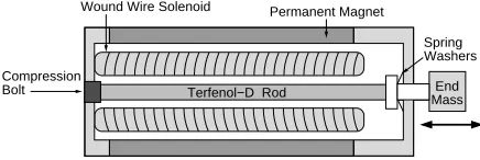
To model the experimental transducer depicted in Figure 2, we assume that the Terfenol-D rod has area A, length ℓ, Young’s modulus Y, density ρ, and Kelvin-Voigt damping parameterC. The longitudinal displacement of the rod tip is denoted byuℓ.
It is shown in [14] that the uniaxial stress σis related to the magnetization, given by (7), via the constitutive relation
σ=Y ε+Cε˙−a1(M −M0)−a2(M −M0)2 (8)
whereY is the elastic modulus at constant magnetization,ε is the longitudinal strain, C is the Kelvin–Voigt damping parameter, a1 is the piezomagnetic coefficient, and a2 is
the magnetostrictive coefficient. The bias magnetizationM0
includes the effects of a permanent magnet and the initial magnetized state of the material.
We make the assumption that strains are uniform and given by
ε(t) = uℓ(t)
ℓ . (9)
Balancing the forces σA for the rod with those of the restoring mechanism yields the lumped model
ρAℓd
2uℓ
dt2 (t) +
CA ℓ
duℓ dt (t) +
Y A ℓ uℓ(t)
=−mℓd
2uℓ
dt2 (t)−cℓ
duℓ
dt (t)−kuℓ(t)
+Aa1[M(H(t))−M0] +Aa2[M(H(t))−M0]2
or, equivalently,
md
2uℓ
dt2 (t) +c
duℓ
dt (t) +kuℓ(t)
=ea1[M(H(t))−M0] +ea2[M(H(t))−M0]2
(10)
where
m=ρAℓ+mℓ , c= CA
ℓ +cℓ, k= Y A
ℓ +kℓ
e
a1=Aa1 , ea2=Aa2.
(11)
The initial conditions areuℓ(0) =u0and dudtℓ(0) =u1. The
magnetizationM is specified by the model (7).
Compression Bolt
Wound Wire Solenoid
Terfenol−D Rod
Mass End Permanent Magnet
Washers Spring
Fig. 2. Magnetic transducer design employed in the control experiments.
The model can subsequently be written as the first-order system
˙
x(t) =Ax(t) +B(H(t))
x(0) =x0
(12)
wherex(t) = [uℓ(t),uℓ˙ (t)]T,x
0= [u0, u1]T and
A=
0 1
−k/m −c/m
B(H) =ea1(M(H)−M0) +ea2(M(H)−M0)2 0
1/m
.
In the subsequent control formulation, the input is taken to beu=H oru=nI whereIdenotes the current applied to the solenoid andnis the number of coils per unit length.
III. PERTURBATIONCONTROLFORMULATION
A. Open Loop Control
We summarize here the open loop optimal control for-mulation detailed in [10], [12]. We let rdenote a reference signal to be tracked,y(t) =Cx(t)denote observations and lete(t) =Cx(t)−r(t)designate the error. The augmented penalty functional is taken to be
J= 1
2[Cx(tf)−r(tf)]
TP[Cx(tf)−r(tf)]
+
Z tf
t0
H −λT(t) ˙x(t) dt
(13)
whereλdenotes the adjoint variable, the Hamiltonian is
H= 1 2[e(t)
TQe(t) +uT(t)Ru(t)]
+λT[Ax(t) + [B(u)](t)],
(14)
and Q, R respectively penalize large errors and control inputs.
Enforcement of necessary conditions to minimize (13) — see [2], [5] — yields the control input relation
u∗
(t) =−R−1
∂B(u) ∂u
T
λ(t) (15)
along with the two-point boundary value problem
˙
z(t) =F(t, z) (16)
wherez= [x, λ]T and
F(t, z) =
"
Ax(t) + [B(u)](t)
−ATλ(t)−CTQCx(t) +CTQr(t)
#
. (17)
To approximate the solution to (16), we employ a finite difference discretization defined on the gridtj=j∆t, where ∆t= tf
N andj = 0,· · ·, N. Lettingzj ≈z(tj), this yields the discrete system
1
∆t[zj+1−zj] = 1
2[F(tj, zj) +F(tj+1, zj+1)] E0z0= [x0,0]T
EfzN = [0,−CTP r(tf)]T.
The solution of (18) can be expressed as the problem of findingzh= [z0,· · ·, zN]which solves
F(zh) = 0. (19)
A quasi-Newton iteration of the form
zkh+1=zkh+ξhk, (20)
whereξk h solves
F′
(zkh)ξhk=−F(zhk), (21)
is then used to approximate the solution to (19). The Jacobian has the form
F′ (zh) =
S0 R0
S1 R1
. .. . ..
SN−1 RN−1
E0 Ef
(22)
where
Si=− 1
∆t
"
I 0
0 I
# −1
2
"
A ∂
∂λB[u
∗
i]
−CTQC −AT
#
. (23)
The representation forRi is similar.
Remark 3.1: It is shown in [13] that an analytic LU
decomposition can be determined for F(zk
h). This signifi-cantly reduces memory requirements and is fundamental for efficient solution since it reduces the dimension of the linear system solution to 8. For the results reported in Section IV, solution of (19), and hence computation of a nonlinear control input, took on the order of 7 seconds.
B. Perturbation Feedback
The relation (15) provides an open loop control signal that is optimal for given Q, R in the absence of model or measurement error. To provide robustness with regard to such uncertainties, we consider perturbation feedback as detailed in [2], [5]. Linearization about the optimality system yields
δx˙(t) =Aδx(t) +Bδu(t)
δy(t) =Cδx(t)
δx(0) = ˆx0
(24)
where δu, δx andδy are first-order variations about u∗ , x∗ andy∗
.
To facilitate experimental implementation, we use classical PI control to computeδu; that is, we take
δu(t) =−KPe(t)−KI
Z t
0
e(s)ds. (25)
The final control input is then
u(t) =u∗
(t) +δu(t). (26)
Remark 3.2: The computation of the open loop inputu∗ is performed off-line and hence does not affect implementation speed. The computation ofδucan be performed at the same speed as classical PI implementation. Hence the experimental implementation of the perturbation control is as efficient as standard PI implementation.
IV. EXPERIMENTALRESULTS
The control algorithm was implemented on a magne-tostrictive transducer having a Terfenol-D rod of length 0.1 m and diameter of 0.0125 m. The preload on the rod was 10-14 MPa and it was subjected to a magnetic field bias of approximately 40 kA/m. Strains at the end of the rod were measured with a capacitive sensor having a sensitivity of 2.5 mV and a bandwidth of 12.5 kHz.
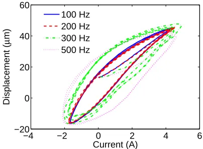
To ensure that the transducer was initialized to the max-imal remanent value prior to characterization and control experiments, each data set was initiated by a half-cycle of a 1 Hz sine wave having an amplitude of 1 volt (this cor-responds to a current of 4.6 amp). Sinusoidal input voltages and corresponding output displacements were subsequently collected at 100, 200, 300 and 500 Hz. As illustrated in Figure 3, the degree of hysteresis exhibited by the device is highly frequency-dependent thus necessitating the incorpora-tion of magnetic moment dynamics via the relaincorpora-tions (3) and (4), and the rod dynamics modeled by (10). Details regarding the characterization of the nonlinear voltage-current relation are provided in [9].
To construct the model, the parameters Mr, η, τ, γ, a1, a2, m, c, k and densities ν1 and ν2 were estimated
through a least squares fit to the combined set of 100, 200, 300 and 500 Hz data. The resulting model fit is plotted in Figure 4. The model with this parameter set was then employed in all control experiments.
To illustrate the tracking capability of the nonlinear control design, experiments were performed at 100, 200, 300, 500, 700 and 1000 Hz. The amplitude of a sinusoidal reference signal was chosen to be 300 ppm which represents an operat-ing regime in which hysteresis and constitutive nonlinearities are significant — see Figure 3.
The open loop and perturbation feedback control results at 200 Hz are respectively plotted in Figures 5 and 6 whereas analogous results at 1000 Hz are plotted in Figures 7 and 8. For both frequencies, it is noted that whereas the open loop control (15) provides reasonable accuracy, the inclusion of the perturbation feedback term (26) improves the accuracy
−4 −2 0 2 4 6
−20 0 20 40 60
Current (A)
Displacement (
µ
m)
100 Hz 200 Hz 300 Hz 500 Hz
−2 0 2 4 6 −20
0 20 40 60
Current (A)
Displacement (
µ
m)
Model Data
(a)
−2 0 2 4 6
−20 0 20 40 60
Current (A)
Displacement (
µ
m)
Model Data
(b)
Fig. 4. Model fit to the experimental data at (a) 200 and (b) 500 Hz.
of both the magnitude and phase. We point out that the characterization experiments did not include 1000 Hz data; hence the accuracy of the nonlinear model-based control at this frequency illustrates the predictive capability of the model.
To provide an initial comparison between the nonlinear control technique discussed here and classical PI designs, the tracking authority achieved with PI inputs at 1000 Hz is illustrated in Figure 9. At this frequency, neither the correct amplitude nor phase are achieved thus yielding errors on the order of the reference signal. It is detailed in [9],
0 0.005 0.01 0.015 0.02 −40
−20 0 20 40 60 80
Time (s)
Displacement (
µ
m)
Commanded Displacement Reference Signal
Error
Fig. 5. Nonlinear open loop tracking authority provided by (15) at 200 Hz.
0 0.005 0.01 0.015 0.02 −40
−20 0 20 40 60 80
Time (s)
Displacement (
µ
m)
Commanded Displacement Reference Signal
Error
Fig. 6. Tracking authority provided by the perturbation feedback control (26) at 200 Hz.
where a complete comparison between the two designs at multiple frequencies are reported, that with the 10 kHz sample frequency, PI control is viable at frequencies below approximately 500 Hz. At higher frequencies, the nonlinear control framework proves advantageous since it provides high accuracy while retaining the implementational effi-ciency of classical PI designs.
0 1 2 3 4
x 10−3 −40
−20 0 20 40 60 80
Time (s)
Displacement (
µ
m)
Commanded Displacement Reference Signal
Error
Fig. 7. Nonlinear open loop tracking authority provided by (15) at 1000 Hz.
0 1 2 3 4
x 10−3 −40
−20 0 20 40 60 80
Time (s)
Displacement (
µ
m)
Commanded Displacement Reference Signal
Error
0 1 2 3 4 x 10⁻³ −50
0 50 100
Time (s)
Displacement (
µ
m)
Commanded Displacement Reference Signal Error
Fig. 9. Tracking authority provided by PI control at 1000 Hz.
V. CONCLUDINGREMARKS
In this paper, we report initial experimental results demon-strating the tracking authority provided by a nonlinear control design for magnetostrictive transducers operating in highly nonlinear and hysteretic regimes. The control design is comprised of a nonlinear open loop component, based on a homogenized energy model, employed in combination with a perturbation PI feedback component. Because the open loop gains are computed off-line, the closed loop implementation provides the efficiency of classical PI control but with signifi-cantly enhanced tracking capability at high frequencies since the model-based open loop control incorporates frequency-dependent hysteresis and constitutive nonlinearities. This significantly extends the results of [10], [12] which focused solely on the numerical implementation of the control design. The present experimental results illustrate sinusoidal track-ing at frequencies up to 1 kHz for a magnetic actuator. How-ever, the unified nature of the characterization framework [14], [19] permits direct extension of the theory to ferro-electric (e.g., PZT) and ferroelastic (e.g., SMA) devices. The numerical implementation of an analogous control design for PZT stages is illustrated in [11] for a variety of reference signals and the experimental implementation of PZT control design is under present investigation.
REFERENCES
[1] U. Ascher, R. Mattheij and R. Russell, Numerical Solution of Boundary
Value Problems for Ordinary Differential Equations, SIAM Classics in
Applied Mathematics, Philadelphia, PA, 1995.
[2] A. Bryson and Y.-C. Ho, Applied Optimal Control, Blaisdell Publishing Company, Waltham, MA, 1969.
[3] P. Ge and M. Jouaneh, “Tracking control of a piezoceramic actuator”
IEEE Transactions on Control Systems Technology, 4(3), pp. 209–206,
1996.
[4] A.G. Hatch, R.C. Smith, T. De and M.V. Salapaka, “Construction and experimental implementation of a model-based inverse filter to atten-uate hysteresis in ferroelectric transducers,” CRSC Technical Report CRSC-TR05-06; IEEE Transactions on Control Systems Technology, to appear.
[5] F. Lewis and V. Syrmos, Optimal Control, John Wiley and Sons, New York, NY, 1995.
[6] J.A. Main and E. Garcia, “Piezoelectric stack actuators and control system design: strategies and pitfalls,” Journal of Guidance, Control,
and Dynamics. 20(3), pp. 479–485, 1997.
[7] J.A. Main, E. Garcia and D.V. Newton, “Precision position control of piezoelectric actuators using charge feedback,” Journal of Guidance,
Control, and Dynamics. 18(5), pp. 1068–73, 1995.
[8] S. Mittal and C-H. Menq, “Hysteresis compensation in electromagnetic actuators through Preisach model inversion,” IEEE/ASME Transactions
on Mechatronics, 5(4), pp. 394–409, 2000.
[9] W.S. Oates, P. Evans, R.C. Smith and M.J. Dapino, “Experimental implementation of a nonlinear model-based magnetic control method,” preprint.
[10] W.S. Oates and R.C. Smith, “Nonlinear perturbation control for magnetic transducers,” Proc 45th IEEE Conf. Dec. and Control, San Diego, CA, to appear.
[11] W.S. Oates and R.C. Smith, “Nonlinear control design for a piezoelectric-driven nanopositioning stage,” CRSC Technical Report CRSC-TR05-43; Journal of Dynamic Systems, Measurement, and
Con-trol, submitted.
[12] W.S. Oates and R.C. Smith, “Nonlinear optimal control techniques for vibration attenuation using nonlinear magnetostrictive actuators,”
Journal of Intelligent Material Systems and Structures, submitted.
[13] R.C. Smith, “A nonlinear optimal control method for magnetostrictive actuators,” Journal of Intelligent Materials Systems and Structures, 9(6), pp. 468–486, 1995.
[14] R.C. Smith, Smart Material Systems: Model Development SIAM, Philadelphia, PA, 2005.
[15] R.C. Smith, C. Bouton and R. Zrostlik, “Partial and full inverse compensation for hysteresis in smart material systems,” Proceedings of the 2000 American Control Conference, pp 2750–2754, 2000. [16] R.C. Smith, M.J. Dapino and S. Seelecke, A free energy model for
hysteresis in magnetostrictive transducers,” Journal of Applied Physics, 93(1), pp. 458–466, 2003.
[17] R.C. Smith, A.G. Hatch, B. Mukherjee and S. Liu, “A homogenized energy model for hysteresis in ferroelectric materials: General density formulation,” Journal of Intelligent Material Systems and Structures, 16(9), pp. 713-732, 2005.
[18] R.C. Smith and S. Seelecke, “An energy formulation for Preisach models,” Proceedings of the SPIE, Smart Structures and Materials 2002, Volume 4693, pp. 173–182, 2002.
[19] R.C. Smith, S. Seelecke, M.J. Dapino and Z. Ounaies, “A unified framework for modeling hysteresis in ferroic materials,” Journal of the
Mechanics and Physics of Solids, 54(1), pp. 46-85, 2005.
[20] R.C. Smith, M.J. Dapino, T. Braun and A. Mortensen, “A homogenized energy framework for ferromagnetic hysteresis,” IEEE Transactions on
Magnetics, 42(7), pp. 1747–1769, 2006.
[21] G. Song, J. Zhao, X. Zhou and J.A. de Abreu-Garc´ı, “Tracking control of a piezoceramic actuator with hysteresis compensation using inverse Preisach model,” IEEE/ASME Transactions on Mechatronics, 10(2), pp. 198–209, 2005.
[22] X. Tan and J.S. Baras, “Modeling and control of hysteresis in magnetostrictive actuators,” Automatica, 40(9), pp. 1469–1480, 2004. [23] X. Tan, R. Venkataraman and P.S. Krishnaprasad, “Control of
hystere-sis: Theory and experimental results,” Smart Structures and Materials 2001, Proceedings of the SPIE, Volume 4326, pp. 101–112, 2001. [24] G. Tao and P.V. Kokotovi´c, Adaptive Control of Systems with Actuator
and Sensor Nonlinearities, John Wiley and Sons, New York, 1996.