Single phase Multilevel Inverter using
Coupled Inductors
Merina David
1, Muhamed Noufal C
2PG Student [PEPS], Dept. of EEE, Federal Institute of Science and Technology, Angamaly, Kerala, India1 Assistant Professor, Dept. of EEE, Federal Institute of Science and Technology, Angamaly, Kerala, India2
ABSTRACT: Multilevel inverters have been attracting in favor of academia as well as industry in the recent decade for high-power and medium-voltage energy control. In addition, they can synthesize switched waveforms with lower levels of harmonic distortion than an equivalently rated two-level inverter. Multilevel converters have received increased interest recently as a result of their ability to generate high quality output waveforms with a low switching frequency. The multilevel concept is used to decrease the harmonic distortion in the output waveform without decreasing the inverter power output. In this work a new class of multilevel inverter with coupled inductor was introduced. No split of the dc voltage capacitor is needed, totally avoiding the voltage balancing problem in conventional multilevel inverters. This inverter is based on the widely used three-arm power module making it very easy to construct. Simulation and experimental results show the validity of this inverter.
KEYWORDS: Multilevel, Coupled inductor, Harmonics, Turns ratio
I.INTRODUCTION
The birth of semiconductor technology and its widespread acceptance and applications fuelled the design of various power converter topologies. Numerous industrial applications have begun to require higher power apparatus in recent years. Some medium voltage motor drives and utility applications require medium voltage and megawatt power level. For a medium voltage grid, it is troublesome to connect only one power semiconductor switch directly. As a result, a multilevel power inverter structure has been introduced as an alternative in high power and medium voltage situations. A multilevel inverter not only achieves high power ratings, but also enables the use of renewable energy sources. Renewable energy sources such as photovoltaic, and fuel cells can be easily interfaced to a multilevel inverter system for a high power application.
For single-phase multilevel inverters, the most common topologies are the cascaded, diode-clamped, and capacitor clamped types [2]. In general, multilevel inverter topologies can be classified into two types: Type I and Type II. Type I uses multiple dc voltage sources and Type II uses multiple (split or clamping) dc voltage capacitors. Type I includes the traditional cascaded topologies. Type II includes the conventional diode-clamped, capacitor-clamped inverters. In terms of single phase multilevel inverters, the disadvantages of the two types are apparent. Type I suffers from the availability of the multiple dc voltage sources. Apart from the conventional multilevel inverters, many more circuit configurations have been designed and implemented. The necessity if such topologies were to reduce the number of components in the configuration and also to reduce the control complexities. Arrival of new topologies resulted in reduced complexity of voltage balancing, less switching losses.
A multilevel inverter with only one dc source and no split capacitors may be the most desirable topology but unfortunately this type of inverter has yet to be discovered. A new topology of multilevel inverter with coupled inductors is attractive in this context. The importance of this innovation lies within using minimum number of elements and PE switches, while increasing number of voltage levels.
II.CONVENTIONAL FIVE LEVEL INVERTER
six are switched in high frequency. The coupled inductors will perform as an adder of the two input voltage at the non common-connected terminals with the common-connected terminal as the output. Actually, without the help of the coupled inductors, the proposed inverter will not be able to output five-level voltage. The switching stresses on all the switches are same and are equal to half the DC link voltage. The topology consists of less number of switches when compared to the conventional multilevel inverter.
III.MODIFIED SEVEN LEVEL INVERTER
In the conventional five level inverter there are redundant switching states. The redundancy is because the coupled inductors are having equal no of turns. If the turns ratio is changed to 1:2 ratio we can increase the number of levels. Thus the modified seven level inverter have the same power circuit as shown in Fig1.The DC link voltage is 2E.The seven levels of the inverter are+2E,+4E/3,+2E/3,0,-2E/3 -2E/3,-2E.
Fig.1 Modified Seven level inverter.
A. ROLE OF THE COUPLED INDUCTORS
It is, in fact, the adoption of the coupled inductors that makes it possible to output seven level voltages with only one DC voltage source. So the role of the coupled inductors will be analysed first.Assuming N2/N1=a, then L1=L, L2=a2L, M=aL.The voltage equations are shown below.
𝑉𝑏𝑛 = 𝐿 𝑑𝑖𝑏
𝑑𝑡 − 𝑎𝐿 𝑑𝑖𝑐
𝑑𝑡 (1)
𝑉𝑐𝑛 = 𝑎2𝐿 𝑑𝑖𝑐
𝑑𝑡 − 𝑎𝐿 𝑑𝑖𝑏
𝑑𝑡 (2)
Solving the above equations we get
𝑉2𝑛 =
𝑎𝑉𝑏𝑛+𝑉𝑐𝑛
1+𝑎 ( 3)
Therefore, V2n is the weighted average of Vb and Vc. Assuming turns ratio equals to 2, Vn is calculated from the
following equation.
𝑉𝑛 =
𝑉𝑏𝑛+2𝑉𝑐𝑛
3 (4)
B. Design of the coupled inductors
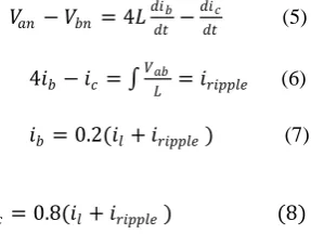
According to (3) and (4), Currents of coupled inductors in can be written down as following equations
𝑉𝑎𝑛 − 𝑉𝑏𝑛 = 4𝐿 𝑑𝑖𝑏
𝑑𝑡 − 𝑑𝑖𝑐
𝑑𝑡 (5)
4𝑖𝑏− 𝑖𝑐= 𝑉𝑎𝑏
𝐿 = 𝑖𝑟𝑖𝑝𝑝𝑙𝑒 (6)
𝑖𝑏= 0.2(𝑖𝑙+ 𝑖𝑟𝑖𝑝𝑝𝑙𝑒) (7)
𝑖𝑐= 0.8(𝑖𝑙+ 𝑖𝑟𝑖𝑝𝑝𝑙𝑒) (8)
Table 1 Switching states of seven level inverter
B.MODULATION METHOD
The switching state of S1 is decided by the sign of V12ref (the reference of V12). S1 is 1 if V12ref 0 and S1 is 0 if V12ref
0.S2 is the complement of S1.Thus we can see that both S1and S2 is switched at fundamental frequency and it is very easy to implement. By analyzing the states we can see that the rest of the switches are switched in high frequency. To decide the switching states of (S3, S5), the following cases will be discussed:
V12ref is between 0 and +2E/3, then switching states are (1, 0).
V12ref is between +2E/3and +4E/3, then switching states are (0, 1).
V12ref is between +4E/3and +2E,then switching states are (0,0)
V12ref is between 0 and -2E/3,then switching states are (0,1)
V12ref is between -4E/3and -2E,then switching states are (1,0)
V12ref is between -4E/3and -2E, then switching states are (1,1).
S1 S2 S3 S4 S5 S6 Vab
1 0 0 1 0 1 +2E
1 0 0 1 1 0 +4E/3
1 0 1 0 0 1 +2E/3
1 0 1 0 1 0 0
0 1 0 1 0 1 0
0 1 0 1 1 0 -2E/3
0 1 1 0 0 1 -4E/3
Table 2 shows the components required for a seven level inverter employing different topology, it is evident from the tables that components required is less for the topology
Table 2 Comparison of elements of different seven level inverter topologies
Diode clamped inverter
Capacitor clamped
Cascaded Inverter
Modified inverter
Switches
12 12 12 6
Diodes
30 - - -
Capacitors
- 21 - -
Pair of coupled
inductors - - -
1
DC sources 1 1 3 1
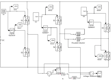
IV.SIMULATION RESULTS
The modified inverter is simulated in MATLAB/Simulink environment. The simulation diagram is shown in Fig 2
The simulation parameters are given in Table 3.
Table 3 Simulation Parameters
The seven level output voltage is shown in Fig 3
Fig .3Output voltage of the modified inverter
The THD analysis of the modified inverter is shown in Fig 4.
Parameters ValuesInput voltage
150V
Load resistance
33Ω
L1 3mH
Fig 4 FFT analysis of modified inverter
VI.HARDWARE IMPLEMENTATION
The hardware model of the seven level inverter was developed and the hardware setup is shown in Fig 5.
Fig.5 Hardware setup
The input given by a 6V battery. A seven level AC voltage with a peak of 6V is obtained as the output. The frequency of the output waveform is 50Hz. The Fig.6 is the obtained output wave form.
Fig.6 Output voltage waveform
The THD of the output waveform is obtained from the harmonic analyser is shown in Fig.7
VII.CONCLUSION
This work has presented a topology of multilevel inverters with coupled inductors. .The advantages with multilevel inverters over two-level inverters are clear. If low disturbances or low switching power loss is wanted, multilevel inverters are certainly a solution. The modified inverter uses less number of power electronic switches and dc sources than the conventional multilevel inverters. This seven level inverter is suitable for low voltage, low / medium power applications
.
REFERENCES
[1] Z. Li, P. Wang, Y. Li, and F. Gao, “A Novel Single-Phase Five-Level Inverter with Coupled Inductors,”IEEE Trans.on Power Electronics,vol. 27 , no. 6, pp. 27 16-2726,June 2012.
[2] J. Rodriguez, J.-S. Lai, and F. Z. Peng, “Multilevel inverters: A Survey of topologies, controls, and applications,”,IEEE Trans.Ind. Electron., vol. 49, no. 4, pp. 724738, Aug.2002.
[3] J. Rodriguez, S. Bernet, P. K. Steimer, and I. E. Lizama, “A survey on neutral-point-clamped inverters,” IEEE Trans. Ind. Electron., vol. 57, no. 7, pp. 22192230, Jul.2010
[4] M.Malinowski, K. Gopakumar, J. Rodriguez, and M. A. Perez, “A survey on cascaded multilevel inverters,”IEEE Trans. Ind. Electron., vol. 57, no. 7, pp. 21972206, Jul.2010
[5] A. M. Knight, J. Ewanchuk, and J. C. Salmon, “Coupled three-phase inductors for interleaved inverter switching,”IEEE Trans.Magn., vol. 44, no. 11, pp. 41994122, Nov.2008