Modeling and Simulation of a DVR with
Intelligent Rule based Controller
Murali Narahari Setty
M-Tech Student Scholar Department of Electrical & Electronics Engineering, Laqshya Institute of
Technology & Sciences, Telangana, India.
Email:
[email protected]
Mr. B. Krishnam raj
Assistant Professor Department of Electrical & Electronics Engineering, Laqshya Institute of
Technology & Sciences,
Telangana, India.
Email: joshephraj015
@gmail.com
Abstract-
The question of the quality of voltage is
rapidly increasing. New technologies are introduced
and we are facing many new power quality
requirements.
Flexible
alternating
current
transmission systems (FACTS) are modern devices
in power transmission and grid stability. The paper
deals with the modeling and designing of a dynamic
voltage restorer (DVR). DVR implements a voltage
sags
detection
algorithm
based
on
DQ
transformation. The proposed algorithm is designed
to operate correctly even during some disturbances
and fault conditions. Several simulations have been
performed in Matlab/Simulink in order to test the
function of the algorithm and the whole DVR system
by using fuzzy logic controller based designing &
modeling of DVR by using MATLAB/SIMULINK.
Keywords—
Dynamic Voltage Restorer, Energy
storage System, Total Harmonic Distortion, Fuzzy
Logic Controller.
I. INTRODUCTION
Voltage sags are now one of the most important power quality problems in the power distribution systems. A voltage sag is a momentary decrease in rms ac voltage (0.1-0.9 p.u. of the nominal voltage), at the power frequency, of duration from cycles to a few seconds. Most voltage sags are caused by remote faults, such as single line- to-ground fault, double line to ground fault and three phase fault on the power distribution system. [2] Recently, power quality problems become a major concern of industries due to massive loss in terms of time and money. Hence, there are always demands for good power quality, which positively resulting in reduction of power quality problems like voltage sag, harmonic, flicker, interruptions and harmonic distortion. Preventing
such phenomena is particularly important because of the increasing heavy automation in almost all the industrial processes. High quality in the power supply is needed, since failures due to such disturbances usually have a high impact on production costs. There are number of methods to overcome voltage sags. One approach is to use Dynamic Voltage Restorers with energy storage. The DVR is a power electronics device that is able to compensate voltage sags on critical loads dynamically. By injecting an appropriate voltage, the DVR restores a voltage waveform and ensures constant load voltage. The DVR consists of Voltage Source Converter (VSC), injection transformers, passive filters and energy storage (lead acid battery). The Dynamic Voltage Restorer (DVR) with the lead acid battery is an attractive way to provide excellent dynamic voltage compensation capability as well as being economical when compared to shunt-connected devices. The DVR is a custom power device that is connected in series with the distribution system. The DVR employs MOSFETs to maintain the voltage applied to the load by injecting three-phase output voltages whose magnitude, phase and frequency can be controlled. [3]
A. Voltage quality in electrical power system:
dim and flickers, loss of synchronization of processing equipment, motors or other process equipment malfunctions, transformers and cables overheating, problems with power factor correction equipment, noise interference to telecommunication lines and many more. Since the whole electrical power network represents a very complex structure, there is no way to control it without any faults and disturbances. Thus, companies are often forced to save its facilities on their own. One of the options for power quality and system stability improvement is to introduce FACTS devices [3].
B. FACTS controllers:
FACTS (Flexible Alternating Current Transmission systems) are alternating current transmission systems incorporating power electronic-based and other static controllers to enhance controllability and increase power transfer capability [4]. The major advantages of FACTS are [5]: power lines transmission capabilities improvement, power flow control, static and dynamic stability enhancement, secure interconnections between neighboring utilities. FACTS controllers are able to control and regulate one or several key parameters in power transmission, such as current, voltage, active, reactive power, frequency or phase angle. Reference [5] divides FACTS into four basic types – series connected, shunt connected, combined series-series and combined series-shunt controllers. The main disadvantage of implementing FACTS is very a high price of these devices and economic requirements. The series controller can be variable impedance, such as capacitor and reactor, or power electronics based variable voltage source. In general, all series controllers inject voltage in series with the line. They are able to compensate voltage sags or swells and eliminate harmonic distortion as well. These are static synchronous series controller (SSSC), thyristor-controlled series capacitor (TCSC) or dynamic voltage restorer (DVR). As in the case of series controllers, the shunt controllers may be variable impedance, variable source, or a combination of these. In basic principle, all shunt controllers inject current into the system at the point of connection. These are static thyristor controlled reactor (TCR), synchronous controller (STATCOM) or static var compensator (SVC). Combined series-shunt controllers are the most flexible and sophisticated FACTS devices. They are able to regulate and affect many different parameters at the same time. One of these devices is unified power flow controller (UPFC).
II. DYNAMIC VOLTAGE RESTORER Dynamic Voltage Restorer (DVR) belongs to series connected FACTS controllers. The primary function of a DVR is to compensate voltage sags and swells but it can also perform tasks such as harmonics elimination, reduction of voltage transients and fault current limitation [6]. DVR is usually installed between a source and a critical load that should be protected. Even the shortest
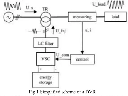
voltage sag can cause serious equipment damage, interruption of production cycles and thus financial losses as well. In general a DVR consists of three parts (Fig. 1.): measuring unit, control, power circuit. The measuring unit provides voltage and current measurements. The outputs are voltage and current analog signals (u, i), which enter the control unit. The control unit converts these signals to their digital representation using A/D converter so that they can be processed by a microprocessor (DSP – digital signal microprocessor). Next part is a voltage sags detection algorithm followed by compensating voltage calculation U_com, which is the voltage needed to be injected into the system in order to remain the load side voltage of purely sinusoidal waveform. Power section consists of a voltage source converter (VSC) equipped with a LC filter to smooth the output voltage, a DC energy storage and an injection transformer (TR) – booster. The basic principle of DVR function is to inject or draw the compensating voltage U_inj to or from the supply voltage U_s in order to mitigate voltage sags or swells on the load side U_load. At every moment the control algorithm compares desired voltage and actual measured voltage. The difference between these two signals is considered as a compensating voltage signal (control signal) U_com, which is directly proportional to compensating voltage U_inj (power circuit). U_com is a digital input signal for a pulse width modulation (PWM) to control the voltage source converter. The VSC converts DC energy stored in an energy storage device (such as batteries or super capacitors) to injecting AC voltage that is to be superimposed to the source voltage. DVR power output depends on the amount of energy that can be stored in the energy storage unit. DVRs are normally installed to protect large electrical energy consumers with the sensitive technologies and devices (2 MVA or more) connected at distribution voltage [9].
Fig 1 Simplified scheme of a DVR
any delay. The very important factor that influences the DVR speed most is the reaction time of the implemented voltage sag detection algorithm. The best DVR systems are able to react within 1 ms.
There are several voltage sags detection techniques, which can be used in DVRs, such as:
Peak value method Missing voltage method, RMS method,
Discrete Fourier transformation, DQ transformation,
Hybrid methods.
A. DQ transformation
In this paper the modeling of a DVR is proposed. Its control algorithm is based on DQ transformation. DQ transformation (dq0 – direct-quadrature-zero) is a mathematical transformation used to simplify the analysis of three-phase circuits [8]. d and q quantities represent rectangular two axis system, which rotates with angular frequency ω [7]. In the case of symmetric three-phase system, introducing of the dq0 transformation reduces three AC quantities (pu) to two DC quantities (d=1, q=0). Any deviations from the steady state condition in abc system reflect in changes of dq0 values in real-time. For unbalanced and asymmetric three phases system applies d≠0, q≠0, 0≠0. According to this presumption it is possible to obtain the difference between desired and instant values dynamically. Therefore, the output compensating voltage can be controlled by PID regulators [3]. The resultant signal is converted back to abc values. DQ transformation can be applied in the case of three phase system and there is a phase-locked loop (PLL) required to lock the synchronization of the compensating voltage in phase with the line voltage before the fault. DQ transformation is calculated as follows [3], [7]:
(1) IV.HYSTERESIS VOLTAGE CONTROL
TECHNIQUE
The control of dynamic voltage restorer is relates with the
Detection of voltage sag/dip, voltage swell, and the generation of the reference voltages for injection purpose.
The sag, swell detection technique is very important task for the appropriate working of dynamic voltage restorer. There are various techniques for the detection of voltage sag, swell. Some are given below. Measuring peak values of input supply,
Measuring of voltage components in dq frame in a vector controller and applying phase locked loop to each phase.
Structure of DVR by using Hysteresis Voltage Control Technique:
Following figure explains the main control diagram of dynamic voltage restorer with hysteresis voltage controller. It mainly consists of three phase IGBT inverter, Energy storage, booster transformer and the hysteresis voltage controller. The hysteresis controller mainly requires two voltage signals, one is from supply side voltage signal and another is from booster transformer which is voltage injected by dynamic voltage restorer. The controller compares these two signals and according to these signals switching pattern is established.
The hysteresis switching method is well explained in fig.5
Fig.2 Hysteresis switching pattern
A. Proportional-Integral Controller
PI Controller is a feedback controller which drives the plant to be controlled with a weighted sum of the error and the integral of that value. The proportional response will be adjusted by multiplying the error by constant KP, called proportional gain.[9] The contribution from integral term is proportional to both the magnitude of error and duration of error. First error will be multiplied by the integral Gain, Ki and integrated to give an accumulated offset that have been corrected previously.
VINTRODUCTIONTOFUZZYLOGIC CONTROLLER
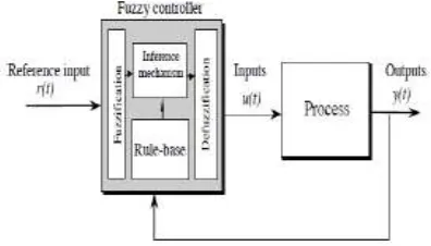
technique. Thus, fuzzy logic controller has been potential ability to improve the robustness of dc-to-dc converters. The basic scheme of a fuzzy logic controller is shown in Fig 5 and consists of four principal components such as: a fuzzy fiction interface, which converts input data into suitable linguistic values; a knowledge base, which consists of a data base with the necessary linguistic definitions and the control rule set; a decision-making logic which, simulating a human decision process, infer the fuzzy control action from the knowledge of the control rules and linguistic variable definitions; a de-fuzzification interface which yields non fuzzy control action from an inferred fuzzy control action [10].
Fig 3 General structure of the fuzzy logic controller on closed-loop system
The fuzzy control systems are based on expert knowledge that converts the human linguistic concepts into an automatic control strategy without any complicated mathematical model [10]. Simulation is performed in buck converter to verify the proposed fuzzy logic controllers.
Fig 4 Block diagram of the Fuzzy Logic Controller (FLC) for dc-dc converters
a) Fuzzy Logic Membership Functions:
The dc-dc converter is a nonlinear function of the duty cycle because of the small signal model and its control method was applied to the control of boost converters. Fuzzy controllers do not require an exact mathematical model. Instead, they are designed based on general knowledge of the plant. Fuzzy controllers are designed to adapt to varying operating points. Fuzzy Logic Controller is designed to control the output of boost dc-dc converter using Mamdani style fuzzy inference system. Two input variables, error (e) and change of error (de) are used in
this fuzzy logic system. The single output variable (u) is duty cycle of PWM output.
Fig 6 The Membership Function plots of error
Fig 7 The Membership Function plots of change error
Fig 8 The Membership Function plots of duty ratio b) Fuzzy Logic Rules:
The objective of this dissertation is to control the output voltage of the boost converter. The error and change of error of the output voltage will be the inputs of fuzzy logic controller. These 2 inputs are divided into five groups; NB: Negative Big, NS: Negative Small, ZO: Zero Area, PS: Positive small and PB: Positive Big and its parameter [10]. These fuzzy control rules for error and change of error can be referred in the table that is shown in Table II as per below:
Table II
Table rules for error and change of error
Fig.9.Matlab/Simulink circuit for proposed DVR
Fig.10. simulation results for balanced sag voltage, voltage injected by DVR, load voltage respectively for PI controller
Case 2 unbalance sag compensation
Fig.11.Simulation results for unbalance sag, DVR voltage, load voltage respectively for Three phase controller
Fig.12.Simulation results for (a) unbalance swell (b) DVR voltage (c) load voltage for single phase Controller
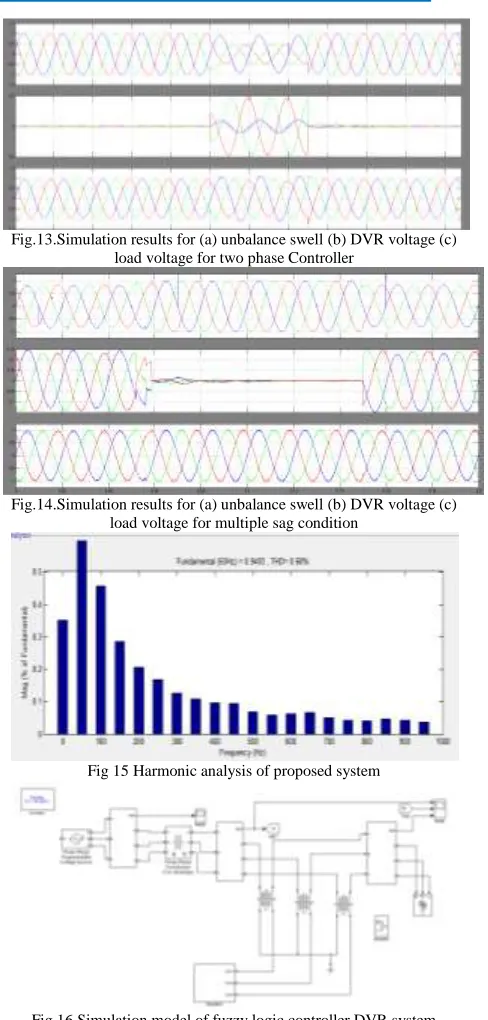
Fig.13.Simulation results for (a) unbalance swell (b) DVR voltage (c) load voltage for two phase Controller
Fig.14.Simulation results for (a) unbalance swell (b) DVR voltage (c) load voltage for multiple sag condition
Fig 15 Harmonic analysis of proposed system
Fig 16 Simulation model of fuzzy logic controller DVR system
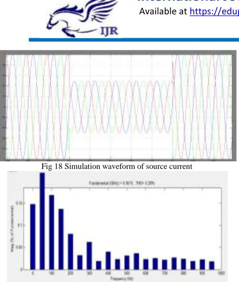
Fig 18 Simulation waveform of source current
Fig 19 Simulation waveform of harmonic analysis of fuzzy based system VI. CONCLUSION
To sum up, the presented DVR simulation model is based on a DQ transformation control algorithm. The main advantages of this control technique are high speed, simplicity and it can be used even during distorted supply voltage waveform. Fuzzy set theory has been widely used in the control area with some application to dc-to-dc converter system. A simple fuzzy logic control is built up by a group of rules based on the human knowledge of system behavior. The entire DVR model was created in Matlab/Simulink and its correct function was verified by several simulation tests. The obtained results showed that, the proposed DVR mitigates voltage sags and harmonics very fast and reliably. Many other parameters and conditions influence the DVR operation. BY using of the fuzzy logic increasing the system performance and improves the THD value comparing of other technique. The right choice of a reliable voltage sag detection method and a proper design of the whole system is the very first step in the developing of a DVR. Thus, the proposed simulation model can support the next research in the field.
REFERENCES
[1] STN EN 50160, “Charakteristiky napätia elektrickej
energie dodávanej z verejnej distribučnej siete,” Slovak technical standard, SÚTN, Bratislava, 2010.
[2] D. Chapman, “Introduction to power quality,” European Copper Institute publication, February 2012. [3] P. Hečko, “Kompenzace krátkodobých poklesů a přerušení napětí v distribuční soustavě,” University of Žilina, faculty of electrical engineering, 2010. Dissertation thesis.
[4] IEEE, “Proposed terms and definitions for flexible AC transmission system (FACTS),” IEEE Xplore digital library, October 1997. ISSN0885-8977
[5] G. N. Hingorani, L. Gyugyi, “Understanding FACTS. Concepts and Technology of Flexible AC Transmission Systems,” New York: IEEE Press, 2000. p. 432. ISBN 0-7803-3455-8
[6] M. N. Tandjaoui, et al., “Sensitive Loads Voltage Improvement Using Dynamic Voltage Restorer,” International Conference on Electrical Engineering and Informatics, 2011. Conference publication. IEEE Xplore digital library
[7] M. Gonzalez, “DQ transformation development for single-phase systems to compensate harmonic distortion and reactive power,” Power Electronics Congress, 2004. CIEP 2004. 9th IEEE International. p. 177- 182
[8] R. A. Kantaria, “A novel technique for mitigation of voltage sag/swell by Dynamic Voltage Restorer,” Electro/Information Technology (EIT), 2010 IEEE International Conference. Conference publication. p. 1-4 [9] M. Minarčík and A. Otčenášová, “Practical measurement of power quality and the possibility of its improvement,” 12-th International Scientific Conference Electric Power Engineering 2011, Kouty nad Desnou, Czech Republic, 2011, p. 478-481, ISBN 978-80-248-2393-5
Author’s Profile:
MURALI NARAHARI SETTY
M.TECH (ELECTRICAL POWER
SYSTEMS) PURSUING In Laqshya
Institute of Technology Sciences ,TANIKELLA(V) ,KHAMMAM(D), TELANGANA, INDIA.
Email id:
[email protected]
.Mr. B. Krishnam raj was born in India in the year of 1987.He received B.Tech degree in Electrical and Electronics Engineering in the year of 2012 & M.Tech PG in Electrical power systems in the year of 2015 from JNTUH, Hyderabad. He is expert in Power system and electrical machines Subjects. He is currently working as An Assistant Professor in EEE Department in Laqshya Institute of Technology and Sciences, Khammam,Telangana State ,India.