Implementation of Characterization
Algorithm for Voltage Sag
Nimmy Anna Kurien1, Jancy Varghese2
PG Student [Power System], Dept. of EEE, Saintgits College of Engineering, Kottayam, Kerala, India1
Assistant Professor, Dept. of EEE, Saintgits College of Engineering, Kottayam, Kerala, India2
ABSTRACT: The Dynamic Voltage Restorer (DVR) topologies in which the compensation schemes are sag type specific, the conventional characterization techniques cannot provide the informations required. Characterization algorithm that can identify the phase(s) affected and can provide information on sag magnitude and phase angle jump are hence needed. In this paper, instantaneous symmetrical component theory based algorithm is used for detection and characterization of voltage sags. The simulation study of the algorithm has been carried out in MATLAB/SIMULINK and the results are presented.
KEYWORDS: Dynamic Voltage Restorer, Phase angle jump, Symmetrical Component Theory, Sag magnitude, Voltage Sag.
I. INTRODUCTION
According to the IEEE 1959–1995 standard, voltage sag is the decrease of 0.1 to 0.9 p.u. in the rms voltage level at system frequency and with the duration of half a cycle to 1 min. Short circuits, starting large motors, sudden changes of load, and energization of trans-formers are the main causes of voltage sags. Since sags are largely due to faults in power system, they are classified into different types depending on the nature of fault which cause it. The four basic types A, B, C and D are shown in Fig.1. A single phase fault causes voltage sag in one phase (type B) at the terminals of a star connected load and in two phases (type C) at the terminals of a delta connected load. A phase-phase fault causes voltage type C sag at the terminals of a star connected load and type D sag at the terminals of a delta connected load. The sag types get transformed as it get propagated in power system, due to the transformers. Type B sag has zero sequence component which gets eliminated as it propagates in the power system through delta-delta or star-delta transformers and gets converted into type C or D respectively.
The sag inception is defined as instant when rms voltage of supply goes below 0.9 p.u. The sag detection time is the time taken by the algorithm to detect sag.
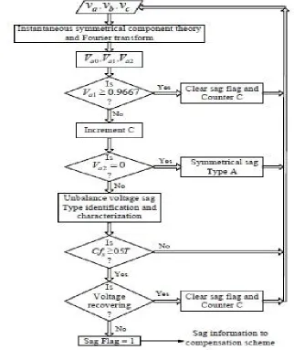
II. CHARACTERIZATION ALGORITHM
The instantaneous symmetrical component theory and Fourier transform can be combined to obtain fundamental symmetrical components. Instantaneous symmetrical components gives the instantaneous changes in voltages. It can hence be used to detect disturbances in a system. The sequence components are calculated as follows:
=1
3
1 1 1
1 1
where = 1 < 120°; , and are the instantaneous zero-, positive-, and negative sequence components,
respectively; are complex and time varying quantities; , are instantaneous three-phase voltages
at the PCC. Fourier transform is applied on the instantaneous symmetrical components of the voltage so that it can work even in presence of harmonics and distortions .
= √2 2
( ) ⁄
( ⁄)
where k= 0, 1 and 2 represent zero, positive, and negative sequence, respectively; ω is the fundamental frequency in
radians per second and Ts is the system time period in seconds.
The fundamental symmetrical components characterize sag by the symmetrical component algorithm (SCA). The SCA characterizes voltage sag using sag-type indicator Ty, characteristic voltage Vch which is a single complex voltage , and
duration of sag.
Type of Sag
Based on the type of faults, sags are classified into four basic types namely A, B, C and D. A single phase fault causes sag of type B, while symmetrical fault causes sag of type A. Phase to phase fault causes sag of type C at star connected load and type D at delta connected load terminals. The fig. 1 represents the four sag types in phasor. In the figure, the presag voltages are given by and ′ where j= a, b and c respectively.
Fig. 1. Phasor voltages of sag types (a) type A (b) type B (c) type C (d) type D
The sag type indicator Ty is calculated by,
=⦟ − ⦟
60°
Each sag type is further classified into three subtypes depending on the phases affected. For example, sag type Db has
Type indicator (Ty) 0 1 2 3 4 5 7
Sag type Ca Dc Cb Da Cc Db A
Table. 1. Numerizing type of sag
III.CHARACTERISTIC VOLTAGE
The characteristic voltage gives the three phase voltage sag. For sag-type C due to a phase-to-phase fault, characteristic voltage is along the affected line voltage; for other sag types, it is the affected phase voltage (sag types A, B, and D have the affected phase voltage as their characteristic voltage), as shown in Fig. 3. The characteristic voltage can be calculated from the sequence components and the sag-type indicator (Ty) using
′= ′− ′+ ′
IV. RESULT AND DISCUSSION
The simulation is carried out in MATLAB/SIMULINK. The sag occurs when the fault is applied from 0.4s to 0.6s. The fig.3 below shows the graph between time vs sag flag. When the sag is detected, sag flag is set at 1.
Fig. 3 Simulation time vs Sag flag
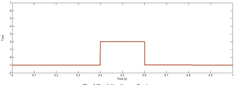
In the fig 4, it shows the graph of time Vs type of sag. The applied sag is phase to phase fault between a and c phases. It is of type Cb where phase b is healthy and other phases are affected. From the table 1, it can be seen that this sag is
numerically denoted by 2.
Fig. 4 Simulation time vs Sag type
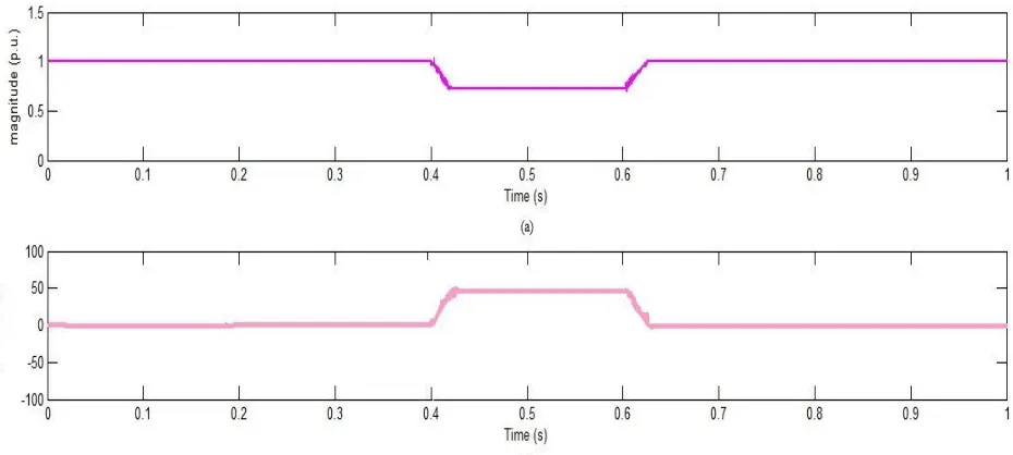
Fig .5 (a) Magnitude of characteristic voltage Vs time. (b) Phase of characteristic voltage Vs time.
V. CONCLUSION
The instantaneous symmetrical component theory based algorithm detects and characterizes voltage dip. It can be used effectively in distorted voltage also. For DVR topologies which require information regarding the phases affected and the sag magnitude, this algorithm can be used. The d-q transform method does not give these information readily. The proposed characterization method utilizing symmetrical component, may prove to be useful for these DVR topologies.
REFERENCES
[1] M. H. J. Bollen, Understanding power quality problems, IEEE press New York, 2000.
[2] R. C. Dugan, M. F. McGranaghan, S. Santoso, and H.W. Beaty, Electrical Power Systems Quality. New York, USA:McGraw-Hill, 2004. [3] J. G. Nielsen and F. Blaabjerg, “A detailed comparison of system topologies for dynamic voltage restorers,” IEEE Trans. Ind. Appl., vol. 41,
no. 5, pp. 1272–1280, Sep./Oct. 2005.
[4] B. Bae, J. Jeong, J. Lee, and B. Han, “Novel sag detection method for line-interactive dynamic voltage restorer,” Power Delivery, IEEE Transactions on, vol. 25, no. 2, pp. 1210 –1211, april 2010.
[5] S. Subramanian and M. Mishra, “Interphase AC-AC topology for voltage sag supporter,” Power Electronics, IEEE Transactions on, vol. 25, no. 2, pp. 514–518, 2010.
[6] M. Bollen, “Algorithms for characterizing measured three-phase unbalanced voltage dips,” Power Delivery, IEEE Transactions on, vol. 18, no. 3, pp. 937 – 944, july 2003.