University of Windsor University of Windsor
Scholarship at UWindsor
Scholarship at UWindsor
Electronic Theses and Dissertations Theses, Dissertations, and Major Papers
1-1-2007
Bio-mechanically driven MEMS power generator for implantable
Bio-mechanically driven MEMS power generator for implantable
medical devices.
medical devices.
Jose Martinez-Quijada University of Windsor
Follow this and additional works at: https://scholar.uwindsor.ca/etd
Recommended Citation Recommended Citation
Martinez-Quijada, Jose, "Bio-mechanically driven MEMS power generator for implantable medical devices." (2007). Electronic Theses and Dissertations. 7112.
https://scholar.uwindsor.ca/etd/7112
BIO-MECHANICALLY DRIVEN MEMS POWER GENERATOR
FOR IMPLANTABLE MEDICAL DEVICES
by
Jose Martinez-Quijada
A Thesis
Submitted to the Faculty o f Graduate Studies
through the Department o f Electrical and Com puter Engineering
in Partial Fulfillm ent o f the Requirements for
the Degree o f M aster o f Applied Science at the
University o f W indsor
W indsor, Ontario, Canada
2007
1*1
Library and
Archives Canada
Published Heritage
Branch
395 Wellington Street Ottawa ON K1A0N4 Canada
Bibliotheque et
Archives Canada
Direction du
Patrimoine de I'edition
395, rue Wellington Ottawa ON K1A0N4 Canada
Your file Votre reference ISBN: 978-0-494-42279-3 Our file Notre reference ISBN: 978-0-494-42279-3
NOTICE:
The author has granted a non
exclusive license allowing Library
and Archives Canada to reproduce,
publish, archive, preserve, conserve,
communicate to the public by
telecommunication or on the Internet,
loan, distribute and sell theses
worldwide, for commercial or non
commercial purposes, in microform,
paper, electronic and/or any other
formats.
AVIS:
L'auteur a accorde une licence non exclusive
permettant a la Bibliotheque et Archives
Canada de reproduire, publier, archiver,
sauvegarder, conserver, transmettre au public
par telecommunication ou par Nntemet, preter,
distribuer et vendre des theses partout dans
le monde, a des fins commerciales ou autres,
sur support microforme, papier, electronique
et/ou autres formats.
The author retains copyright
ownership and moral rights in
this thesis. Neither the thesis
nor substantial extracts from it
may be printed or otherwise
reproduced without the author's
permission.
L'auteur conserve la propriete du droit d'auteur
et des droits moraux qui protege cette these.
Ni la these ni des extraits substantiels de
celle-ci ne doivent etre imprimes ou autrement
reproduits sans son autorisation.
In compliance with the Canadian
Privacy Act some supporting
forms may have been removed
from this thesis.
While these forms may be included
in the document page count,
their removal does not represent
any loss of content from the
Conformement a la loi canadienne
sur la protection de la vie privee,
quelques formulaires secondaires
ont ete enleves de cette these.
Abstract
Acknowledgements
I want to take this opportunity to acknowledge the people without whom this work would not have been possible. Firstly, I want to express my sincere gratitude to my thesis supervisor, Dr. Sazzadur Chowdhury, for giving me the opportunity to work in the MEMS field, for his expert guidance and financial support, as well as for accepting my topic o f thesis, which became my greatest motivation from the moment I proposed him the core idea in a piece o f paper to the completion o f this thesis.
I want to deeply thank my beloved wife, Veronica Elizabeth Camacho Zuniga for her immense love and patience in this great journey and for continuously encouraging me with an ample smile. She has been for me a model o f braveness and strength everyday and especially when she brought our little son, Pepito, to life on May 15th, 2006. Now at the age o f 18 months, he is an energetic baby that fills up o f happiness our lives. Pepito and Eli did not know, when peacefully sleeping at night, that they were inspiring a research work that sooner o f later will help improve the quality life o f the human being.
Traduction (Translation) - Quiero agradecer profundamente a mi amada esposa, Veronica Elizabeth Camacho Zuniga, su inmenso amor y paciencia en esta gran aventura y p o r impulsarme continuamente con una amplia sonrisa. Ella ha sido para mi un modelo de valentla y fortaleza cada dla y especialmente cuando trajo a nuestro pequeho hiio, Pepito, a la vida el 15 de Mayo de 2006. Ahora a sus 18 meses de edad, el es un bebe lleno de energla, que colma de felicidad nuestras vidas. Pepito y Eli no sabian, mientras dormian tranquilamente en la noche, que inspiraban un trabajo de investigation que tarde o temprano ayudara a mejorar la calidad de vida del ser humano.
The greatest acknowledgement to my Mom, M aria del Carmen Quijada Cisneros, and to my Dad, Jose Martinez Pichardo, whose love has accompanied us in our way from Mexico, from where their efforts brought to reality our dream o f living and studying in Canada, giving us the unconditional and generous support that allowed us to live without lacking anything, even with the privilege o f knowing the world, and thanks to whom I have a past o f delightful memories and a future ahead.
Traduction (Translation) - El mas grande reconocimiento a mi Mama, M aria del
My special gratefulness to my friend and godmother o f my son, Dr. Irma Araceli Flores Tapia, whose dedicated work kept my eyes open to the books, the snow and the sky. But also for her attention and curiosity to my ideas and for joining me in the fight to improve life conditions o f the human being.
Traduction (Translation) - M i especial gratitud a mi amiga y madrina de mi hijo, la Dra. Irma Araceli Flores Tapia, cuyo dedicado trabajo mantuvo mis ojos abiertos a los libros, a la nieve y al cielo. Pero tambien p o r haber puesto su atencion y curiosidad en mis ideas y haberse unido a mi en la lucha p o r mejorar las condiciones de vida del ser humano.
And many thanks to E li’s family and the rest o f my family, as well as to our friends, who shape the warm environment I have lived and worked in, who from distance pray for us, and whom I keep incessantly in my heart.
“Im agina que y a estas ahi, imagina que y a lo lograste, imagina que y a lo tienes ! y dale gracias a Dios ”
(Translation) “Imagine that you are already there, imagine that you already achieved it, imagine that you already have i t ! and thank G od”
-M aria del Carmen Quijada Cisneros
“E l reto del hombre no es veneer al adversario, sino a la adversidad”
(Translation) “The challenge o f the mankind is not to defeat the adversary, but the adversity ”
Table of Contents
A b s tr a c t... iii
A c k n o w le d g e m e n ts... iv
L ist o f T a b le s... vii
L ist o f F ig u r e s ... viii
C H A P T E R 1: In tr o d u c tio n ...10
1.1
Problem Identification... 10
1.2
Goals...11
1.3
Background... 13
1.3.1 Energy Storage Alternatives for Biomedical Implants... 13
1.3.2 State of the Art in Microscale Power Generation...14
1.3.3 Electromagnetic Induction Micropower Generators... 16
1.3.4 In-body Micropower Generation... 18
1.4
Principal Results...21
1.5
Organization of Thesis... 22
C H A P T E R 2: D evice C on cep t...24
2.1
Fundamental Structure and Components...24
2.2
Operating Principle... 26
2.3
Key Features...27
2.4
Target Application Areas... 29
C H A P T E R 3: M icrogen erator D e sig n ... 31
3.1
Function of a Pacemaker... 31
3.2
Design Requirements... 33
3.3
Mathematical Model of Axial Flux Brushless Power Generators...35
3.4
Rotor Geometry...
36
3.5
Magnetic Material Selection...
38
3.6
Magnetization of NdFeB Magnets... 39
3.7
Lubrication System... 43
3.8
Design Strategy and Final Device Specifications... 47
C H A P T E R 4: M icrogen erator F a b rica tio n ... 53
4.1
Fabrication Strategy... 53
4.2
Rotor F abrication...54
4.3
Stator Fabrication...63
4.4
Assembly / Encapsulation of the Microgenerator... 71
C H A P T E R 5: M icrogen erator M ou n tin g and A ctuation S y s te m ...74
5.1
Silicone Encapsulation Package...75
5.2
Driving Pressure...78
5.3
Mechanical Input to the Microgenerator...80
C O N C L U S IO N S ... 82
R E F E R E N C E S ... 87
List of Tables
List of Figures
Figure 1. Three types o f electromagnetic induction microgenerators [17]... 17
Figure 2. A conceptual 3D model o f the microgenerator...25
Figure 3. Close-up view o f the 3D model o f the microgenerator... 25
Figure 4. Operating principle o f the microgenerator... 26
Figure 5. Stacks and arrays o f microgenerators for increased power generation... 28
Figure 6. Multiple-axes mounting system o f the microgenerator...28
Figure 7. Excitation and conduction system and major muscles in the human heart [1]. .32 Figure 8. Typical electrocardiogram (ECG) and its characteristic waves [1]... 33
Figure 9. Block diagram o f a typical cardiac pacemaker...34
Figure 10. Thickness parameters used to determine the shape factor/?...35
Figure 11. Semicircular rotor geometry... 37
Figure 12. Circular rotor geometry... 37
Figure 13. Capacitor discharge magnetization circuit used to implement M FSSM ...39
Figure 14. Stages o f the MFSSM magnetization method... 40
Figure 15. 3D Model used for simulation o f the MFSSM magnetization method... 41
Figure 16. Simulation results o f magnetic flux density in the MFSSM m ethod...42
Figure 17. Magnetic flux density along a line crossing through the pole pieces... 42
Figure 18. Detail o f the interface between a semicircular rotor and the shaft...43
Figure 19. Detail o f the interface between a circular rotor and the shaft... 44
Figure 20. Conceptual 3D Model o f the Ni-P-(IF-W S2) solid lubricant fd m ...46
Figure 21. Maximum output voltage as a function o f number o f embedded pole pairs. ..48
Figure 22. Output voltage waveform o f a microgenerator with semicircular rotor... 49
Figure 23. Output voltage waveform o f a microgenerator with circular rotor... 49
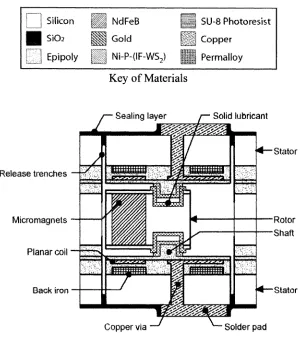
Figure 24. Cross-sectional view o f the final microgenerator with a semicircular rotor.... 51
Figure 25. Cross-sectional view o f the final microgenerator with a circular rotor...51
Figure 26. Key o f materials used in the fabrication process...54
Figure 27. Rotor fabrication step 1 - thermal growth o f bottom Si02 seed layer...54
Figure 28. Rotor fabrication step 2 - growth o f first epipoly structural layer... 55
Figure 29. Rotor fabrication step 3 - patterning o f openings for NdFeB pole pieces...55
Figure 30. Rotor fabrication step 4 - deposition o f NdFeB thick film using PLD ...56
Figure 31. Rotor fabrication step 5 - removal o f excess NdFeB by polishing...56
Figure 32. Rotor fabrication step 6 - deposition o f S i0 2 seed layer on top o f the wafer.. 57
Figure 33. Rotor fabrication step 7 - growth o f second epipoly structural layer...57
Figure 34. Rotor fabrication step 8 - patterning o f the rotor-stator gap... 58
Figure 35. Rotor fabrication step 9 - patterning o f destabilizer shape and shaft holes. ...58
Figure 36. Rotor fabrication step 10 - electroplating o f gold for the destabilizer... 59
Figure 37. Rotor fabrication step 11- electroless deposition o f solid lubricant film... 59
Figure 38. Rotor fabrication step 12 - patterning o f solid lubricant film in shaft holes. ..60
Figure 39. Rotor fabrication step 13 - deposition o f bottom sacrificial SU-8 layer...60
Figure 40. Rotor fabrication step 14 - patterning o f the rotor geometry...61
Figure 41. Rotor fabrication step 15 - deposition o f top sacrificial SU-8 layer... 61
Figure 44. IntelliSuite™ simulation result o f rotor process sequence (full view)... 62
Figure 45. Stator fabrication step 1 - thermal growth o f top SiC>2 insulating layer... 63
Figure 46. Stator fabrication step 2 - electroplating o f Permalloy® layer... 63
Figure 47. Stator fabrication step 3 - patterning o f the back-iron piece... 64
Figure 48. Stator fabrication step 4 - growth o f first epipoly structural layer... 64
Figure 49. Stator fabrication step 5 - patterning o f planar coil tracks and term inals...65
Figure 50. Stator fabrication step 6 - electroplating o f back-copper layer... 65
Figure 51. Stator fabrication step 7 - patterning o f vias to the planar coil term inals...66
Figure 52. Stator fabrication step 8 - copper electroplating o f planar coil and vias... 66
Figure 53. Stator fabrication step 9 - polishing o f excess copper... 67
Figure 54. Stator fabrication step 10 - growth o f second epipoly structural layer... 67
Figure 55. Stator fabrication step 11 - pattering o f the shaft... 68
Figure 56. Stator fabrication step 12 - electroless deposition o f the solid lubricant film. 68 Figure 57. Stator fabrication step 13 - patterning o f solid lubricant film around shaft. ...69
Figure 58. Stator fabrication step 14 - patterning o f rotor-release trenches...69
Figure 59. IntelliSuite™ simulation result o f stator process sequence (cross section 1). .70 Figure 60. IntelliSuite™ simulation result o f stator process sequence (cross section 2). .70 Figure 61. IntelliSuite™ simulation result o f stator process sequence (full view ).71 Figure 62. Assembly & Encapsulation step 1 - alignment o f rotor and stators... 71
Figure 63. Assembly & Encapsulation step 2 - Assembly and b o n d in g ...72
Figure 64. Assembly & Encapsulation step 3 - Solder pads pattering and rotor release..72
Figure 65. Assembly & encapsulation step 4 - vacuum sealing...73
Figure 66. The microgenerator and actuation mechanism in a silicone rubber capsule. ..75
Figure 67. Silicone encapsulation o f the complete pacemaker system...76
Figure 68. Attachment o f the microgenerator to lateral hinges and driving rods... 76
Figure 69. Operation o f the breathing actuation mechanism...77
Figure 70. The human ventilatory system as shown in [55]...79
Figure 71. Waveforms o f the mechanical input to the microgenerator... 80
Figure 72. The MEMS power generator as a power supply o f a blood pressure sensor... 83
Figure 73. The MEMS power generator as a power supply o f a drug delivery system .... 84
CHAPTER 1
Introduction
“The fin ite supply o f energy is the prim ary drawback to battery power. Moreover, there
are many situations where replacement or recharging o f batteries is inconvenient or
impossible. Examples include devices implanted in the human body,
e.g. pacemakers and cochlear implants, and devices intended f o r long duration. ”
-D avid P. Arnold [17]
1.1 Problem Identification
and a sensor subsystem are used in advanced pacemakers to monitor the operating conditions o f the pacemaker and physical activity o f the recipient and then change the shape and frequency o f the output pulses accordingly, aiming to increase the therapeutic performance o f the pacemaker and make more efficient utilization o f the energy in the battery to extend its lifetime. Although the electronic modules o f the pacem aker have been successfully miniaturized, the volume o f a typical pacemaker battery ranges from 5 to 8 cm3, which is nearly half the volume o f the entire pacemaker system [4], The weight o f pacemaker batteries ranges from 12.5 to 15.5 grams and their dimensions average 49 mm x 46 mm x 6 mm [4], For a device that is to be implanted, a minimum size and weight are desirable in order to prevent excessive strain, irritation and swelling o f surrounding tissues, conditions that, if not controlled properly, could lead to rejection o f the implant. The risk, cost and mental and physical pain associated with recurring surgeries, the use o f toxic substances in batteries, along with the need for less invasive smaller size longer life implantable medical devices, make it necessary to seek for alternative energy sources for cardiac pacemakers.
1.2 Goals
source o f higher power per unit volume at a lower cost, and substantially reduce the recurrence o f implant replacement surgeries due to battery exhaust.
M otivated by this philosophical thinking, the main goal o f this research work is to develop a microsized power generator capable o f delivering continuous energy to implantable medical devices, cardiac pacemakers in particular, in order to overcome the problem o f limited energy content o f conventional batteries. The approach undertaken to achieve this goal is to actively convert the kinetic energy present in the human body in the form o f physiological motion o f the body organs, into electricity through the use o f an electromagnetic induction micropower generator built with the MEMS technology.
The work o f development in this thesis was fractioned into the following specific goals:
1. Definition o f the fundamental structure and components o f a microgenerator capable to generate electrical power from the movements present in the human body, clearly defining its operating principle and identifying key features over other types o f microgenerators that could potentially make it more suitable for biomedical implant applications.
2. Identification o f the possible application areas o f the microgenerator and selection o f a top-priority target device. Then Investigation o f the power requirements o f the selected target device.
3. Design o f the microgenerator to meet the power requirements o f the target device, by firstly identifying an analytical model that allows predicting the behavior o f the microgenerator and optimizing the design parameters to achieve maximum performance within the microscale dimensions expected for the device and the constraints imposed by the available materials and fabrication technologies.
4. Identification o f the possible variations in the geometry o f the microgenerator or its parts as well as the materials and methods that can lead to overcome the main design challenges and to meet the power requirements o f the target device.
6. On the base o f the final design specifications, the elaboration o f an industry standard fabrication process table for the physical construction o f the device. Then verification o f the process by means o f computer simulation.
7. Definition o f a mounting and actuation scheme, as well as a suitable packaging, that enable the integration of the device with the circuitry and functional modules o f the target device into the target environment.
1.3
Background
1.3.1 Energy Storage Alternatives for Biomedical Implants
expensive or difficult-to-obtain materials. Other linked setbacks, like the risks o f corrosion, leakage, production o f hydrogen as a by-product or radioactive contamination have prevented these batteries from being widely used to power implantable medical devices, especially cardiac pacemakers.
1.3.2 State of the Art in Microscale Power Generation
The MEMS technology offers the advantage o f realizing microsizcd devices such as sensors, actuators, resonators, microfluidic and micro-optic devices that can be batch fabricated. In recent years some design examples [8-11] have been published where m iniature or microsized electromagnetic induction power generators have been created, some in MEMS technology, to enable microscale power generation. In [8], an intemal- combustion tubular micro-engine has been presented where a piston reciprocates between two opposite combustion chambers due to the pressure generated by the expansion o f gas produced by the ignition o f a fuel-oxidant-catalyst mixture. The piston, containing a permanent magnet, induces a voltage across a coil that is wound around the tubular engine. With a stroke o f 60 to 70 mm and 8 mm in diameter, the device is capable to generate 20 W RMS power. An axial flux permanent magnet (AFPM) brushless microgenerator has been reported in [9] where an external gas flow spins a microturbine, which in turn causes a permanent magnet embedded SU-8 polymer rotor to rotate between two silicon stators embedded with electroplated planar copper coils. To reduce friction, the generator employs 1 x 1 x 3 mm conventional ball bearings. With a diameter o f 7.5 mm, the device is capable o f producing 1.1 mW RMS power at 1.19 Vpp per stator when the rotor is driven at a rotational speed o f 30,000 RPM.
Electromagnetic induction and piezoelectric transduction have also been exploited to create microsized power generators that rely on the resonant characteristics o f a mass- spring-damper system to generate electricity, as reported in [12-15]. These devices yield maximum power when externally vibrating forces match the resonant frequency o f the system. In vibration-based electromagnetic induction generators, like those presented in [12-14], an external vibration causes a permanent magnet to oscillate through a conductor coil, thereby inducing a voltage across its terminals. In vibration-based piezoelectric generators, like that presented in [15], an external vibration causes a proof mass to oscillate and stress a flexible structure that has been coated with layers o f piezoelectric material, thereby straining the piezoelectric film and causing an electric charge differential to appear on the film surface. A comprehensive review o f vibration- powered microgenerators is available in [16].
M icropower generators that require injection o f a driving fluid have necessarily a flow output. Miniature combustion engines require fuel and produce gaseous emissions, as well as excessive noise and heat. Hence, generators like these cannot be packaged in a sealed container, similarly to the generators that have their rotor mechanically coupled to an external source o f torque. As sealing is not possible in these devices, they cannot be used to power implantable medical devices, where complete isolation between the im plant’s inner parts and the live tissue is mandatory to prevent rejection.
On the other hand, though vibration-powered generators can be encapsulated and yield enough power to energize most biomedical implants, including pacemakers, their life span is severely compromised due to the fatigue failure o f their vibrational springs. The fatigue failure occurs due to cyclic strain that flexible structures suffer over an extended period o f operation. Furthermore, vibration-powered generators must be exposed to sustained vibrations at their specific resonant frequency for them to output maximum power; however, such conditions do not naturally exist in the human body where only
lo w frequency quasi-periodic and random m echanical m ovem ents are present. T hese
1.3.3 Electromagnetic Induction Micropower Generators
Electromagnetic induction permanent magnet microgenerators are o f special interest due to their simple operation mode, their potentially high power density and efficiency [17]. Nowadays however, batch manufacturability, further miniaturization and enhancement o f the total power output, power density and efficiency o f these microgenerators face two major challenges: the implementation o f physically small permanent magnets with strong magnetic properties, i.e. high remanence (Br), high coercivity (Hc) and high energy product (BH max); and the development o f micro scale low-friction bearings. In [17], miniature and microscale permanent magnet power generators developed over the last decade are classified into three groups:
Rotational generators - Designed for continuous rotational motion under a steady driving torque provided by a fluid-powered microturbine or heat engine. A conceptual drawing o f such generator is shown in figure la. They often operate at high rotational velocities, due to the small diameter o f their rotor, thus enabling a high rate o f change o f magnetic flux per unit time. They can produce power in the order o f tens o f watts.
Oscillatory generators - A conceptual drawing o f such generator is shown in figure lb. They are driven by forced environmental vibrations in resonance mode and rely on small relative displacements between a permanent magnet and a coil. Operate at lower electrical frequencies and lower power densities than rotational generators. The basic design utilizes a mass-spring-damper system and maximum power is achieved at the mechanical resonant frequency. In the case o f MEMS oscillatory generators said resonant frequency is well above the range o f naturally occurring vibrations (1 Hz to 1 kHz).
Magnetic rotor
Coils
(a)
Permanent Magnet
Coils
Eccentric Magnetic rotor
Coils
I
(C)
Though a few devices, like that in [8], do not belong to any o f these categories, the above classification can be considered comprehensive. The author o f [17] cites 14 small-scale electromagnetic induction power generation systems pertaining to the rotational category and 19 in the oscillatory category. Distinctive examples in these two categories are the devices o f [9] and [14], respectively. In the category o f hybrid generators four systems are cited: three o f them are designed to power Automatic Generating System (AGS) wristwatches [18-23], They have a non-magnetic oscillating weight that occupies the rear portion o f the watch and oscillates due to the movements o f the w earer’s wrist. The oscillating weight can either drive a gear train that increases rotational speed by hundred times and spins a small permanent magnet generator [18-21], or wind a circular spring that when reaches a maximum torque is released, starting a millimeter-scale generator through a gear train [22-23]. The fourth hybrid system [24] cited in [17], consists o f a pendulum, formed by two permanent magnets in opposite polarities, that oscillates freely around a shaft across a set o f six round-shape conductor coils accommodated in circumference beneath the rotation plane o f the pendulum. In a computer simulation, this hybrid generator is placed in horizontal or vertical position and exposed to radial short- distance continuous vibration, seeking to cause a self-sustained rotational movement o f the pendulum, thereby producing continuous output o f electricity. The aim o f the device is to convert small amplitude linear vibration into rotary motion, not stochastic movement, like the non-resonant generators used in watch industry. Results o f simulation o f millimeter-scale and microscale devices in [24] suggest the feasibility to produce a MEMS generator o f this design with a pendulum o f 440 pm length. In a 1.5 cm 3 prototype, built with conventional windings and two millimeter-size NdFeB magnets mounted on a pendulum, a vibration o f 75 pm amplitude at 80 Hz is capable to induce synchronous rotation at 4800 RPM and generate 3 mW power.
1.3.4 In-body Micropower Generation
The authors o f [25] presented a macro scale handmade variable capacitance electrostatic power generator to be driven by the contraction o f the heart ventricles during the heartbeat, aiming to produce power for a cardiac pacemaker. The feasibility o f the generator was demonstrated in a vibrating table that emulated the motion o f the left ventricular wall following in real-time the readings o f an accelerometer attached to a live canine heart. The generated power was supplied to a cardiac pacemaker, which then stimulated the animal heart. A mean power o f 36pW was generated, which was enough to power the cardiac pacemaker for continuous generation and pacing for more than two hours. A simple variable-frequency variable-width pulse oscillator circuit made with off- the-shelf CMOS inverters was used as a constant-rate pacing cardiac pacemaker for the experiment. The electrostatic generator consists o f an enlarged surface area variable capacitor with one o f its plates fixed and the other movable and attached to a mass-spring system to form a linear resonant mechanism tuned to a harmonic component o f the heartbeat in the range o f 1 to 2 Hz, such that the capacitance o f the variable capacitor changes by an external vibrating force and maximum power is attained at resonance. The total spring constant o f the system was calculated to be 1100 N/m, and the total mass suspended by the steel springs was estimated to be 780 grams for a resonant frequency o f 6.0Hz. The generator also requires a starting power supply, i.e. a battery, to charge the variable capacitor with an initial DC voltage only once at the very beginning o f power generation.
In spite o f this, the experiment successfully certifies that the motion o f the heart is capable to drive a generator to produce power for a cardiac pacemaker that in turn maintains the heart motion, in this way giving raise to a closed loop self-sustained permanent power generation-stimulation system.
A bio-thermo-electrical generator has been reported in [26-27] to recharge a battery in an implantable device. The design exploits the Seebeck effect in which a voltage is created in the presence o f a temperature differential between two junctions o f dissimilar metals or semiconductors. The bio-thermal generator is to be implanted directly under the skin in order to exploit the temperature difference between the patient’s body and the outer environment at opposite faces o f the device. The patient is responsible for providing a continuous temperature difference, either putting on or taking o ff clothing, moving to a warmer or colder environment, or topically applying an irritant substance or ice.
In this approach large contact area surfaces are needed in order to assure sufficient heat transfer through the device, fact that complicates its miniaturization. Medical conditions like fever or stress, or physical activity can negatively affect the temperature differential necessary for power generation. As implantation o f the device is to be done under the skin, it cannot be integrated to medical devices targeting deep-body organs, like cardiac pacemakers. Moreover, as this generator is intended to recharge a battery, the limited number o f charge-discharge cycles o f such a battery will eventually result in an early end o f life o f the implant.
The authors o f [28-30] have presented a micropower fuel cell that employs oxygen and glucose in the blood stream and other ambient body fluids to produce electricity. In its electrochemical process, the fuel cell outputs water and CO2 as byproducts, which the
ferricyanide is used as an oxidant that accepts the electrons, thereby closing the external electrical circuit. Simultaneously, electrostatic attraction causes protons in the anode chamber to diffuse across the PEM into the cathode chamber, where they recombine with oxygen and form water. A nanoporous polycarbonate membrane keeps the yeast microbes trapped in the anode chamber but allows circulation o f glucose into the chamber and wastes out o f it. With pore size o f 10 nm, the membrane also prevents antibodies, which size ranges from 10 to 25 nm, from entering the anode chamber, isolating it from the immune system.
The power produced by this fuel cell still falls below the power requirements o f most medical implants. In the device, the production o f electricity will continue as long as the yeast microbes survive. However, the delicate habitat inside the anode chamber, in close relation to the human organism, may be interfered and endangered by agents such as viral infections or medication, that can easily penetrate the porous membrane. Also medical conditions like diabetes may take the fuel cell to an unpredictable situation. In case o f failure to preserve the health o f the anode chamber microbes, a violent rejection process would be rapidly initiated by the immune system.
1.4 Principal Results
The outcomes o f this research work are the following:
1. A MEMS electromagnetic induction axial flux permanent magnet (AFPM) brushless power generator has been developed for use in a cardiac pacemaker to replace conventional batteries. In the system, an asymmetrical planar rotor embedded with microfabricated NdFeB alternate-polarity permanent magnets oscillates around a central shaft due to the thorax motion during breathing to induce a voltage in two microfabricated planar copper coils embedded in two stators. The microgenerator does not need any external supply o f fluid, as necessary in some other types o f microgenerators.
1.0 V open circuit RMS voltage per stator. The circular rotor microgcnerator has a rotor footprint area o f 3 x 3 mm2 and can generate 59.73 mW RMS pow er with 9.0 V open circuit RMS voltage per stator. The generated voltage and power are sufficient to meet the power requirements o f a typical cardiac pacemaker.
3. A novel magnetization method to produce alternate polarity thin film micromagncts in close proximity was developed and verified through 3D finite element analysis simulation.
4. A nanoparticle based thin film solid lubrication system was identified as a suitable means to minimize wear and energy losses due to friction between the rotor and the shaft, thereby improving the efficiency and extending the lifetime o f the microgenerator.
5. A detailed fabrication process sequence was developed to fabricate the device. The developed process sequence was verified by simulation using IntelliSuite, an industry standard MEMS design and fabrication tool.
6. A biocompatible mounting and actuation system that enables the thorax muscles to drive the proposed microgenerator from breathing was presented and designed to ensure power generation for the pacemaker even when the recipient is at rest.
1.5 Organization of Thesis
system o f choice are illustrated and finally the simulation results for the output voltage o f the microgenerator are presented along with final specifications o f two generator designs: one with a semicircular rotor and one with a circular rotor. Chapter 4 details the m icrofabrication process steps for the physical construction o f the rotor and the two stators o f the microgenerator and the procedure for assembly/encapsulation o f these major parts into a single functional unit. Chapter 5 reveals a novel mounting and actuation scheme where the microgenerator is submerged in a liquid silicone ambient inside a soft silicone rubber capsule that provides biocompatibility between the microgenerator and the live tissue, at the same time offering a reliable way to maintain the oscillation o f the rotor, hence power generation, when the recipient o f the implant is at rest or sleeping, only relying on the contraction o f the thorax muscles during breathing. The chapter begins with a description o f the proposed mounting and actuation system, then introduces the pleural pressure in charge o f driving the microgenerator and ends with a description o f the forces that form the mechanical input to the microgenerator in the breathing actuation mechanism.
CHAPTER 2
Device Concept
In this chapter the fundamental concept o f the proposed bio-mechanically driven MEMS power generator is presented. Its fundamental components, their functions, and operating principle are explained. The chapter also covers the features that make the microgenerator suitable for medical implantable devices and points out the other possible target devices in which the microgenerator might be used as a power supply instead o f a conventional battery.
2.1 Fundamental Structure and Components
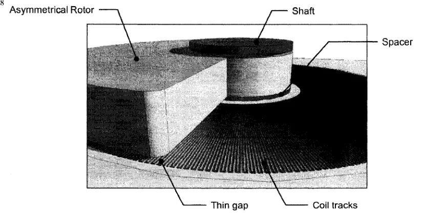
Figure 2. A conceptual 3D model of the microgenerator.
Asymmetrical Rotor Shaft
Thin gap Coil tracks
Figure 3. Close-up view o f the 3D model o f the microgenerator.
2.2 Operating Principle
The overall movements o f the human body and the local movements o f the region where the system is implanted provide driving force to the microgenerator. The motion o f the thorax during breathing, head turning, mechanical activity o f the extremities or even the movement o f internal organs like the heart or stomach, cause the asymmetrical rotor to leave its initial stable position (figure 4a) and change its previous axis orientation (figure 4b), such that the Earth’s gravitation alone can generate a torque that triggers oscillation o f the rotor. The rotor oscillates for a certain time (figure 4c) and finally reaches a new stable position (figure 4d).
(d)
Figure 4. Operating principle o f the microgenerator.
(a) Initial stable position o f the rotor, (b) The rotor axis orientation changes on excitation, (c) The rotor oscillates after excitation, (d) New stable position o f the rotor.
Due to the mechanical oscillation o f the rotor, a changing magnetic axial flux cutting through the planar coil induces a voltage across its terminals following Faraday’s Law o f electromagnetic induction. The kinetic energy acquired by the rotor on excitation eventually dissipates and oscillation stops due to a couple o f factors: (a) mechanical damping, caused by friction between the rotor and the shaft; (b) electromagnetic damping, caused by the induced current in the planar coil, that in turn causes a magnetic
field that opposes the m otion o f the rotor. O nce the kinetic energy o f the rotor has been
dissipated a new change in the orientation o f the rotation plane is necessary to trigger a new energy generation cycle.
energy can be stored in a MEMS fabricated super capacitor to provide stable power to the target device even during certain periods o f inactivity.
For its construction, according to the classification in [17], the microgenerator belongs to the category o f hybrid generators. However is not intended to convert forced linear vibrations in the radial direction into continuous rotational motion, though it is capable to do this kind o f conversion, but to convert changes in inclination angle (or axis orientation) and stochastic motion, which are the predominant situations in the human body, into rotational motion.
2.3 Key Features
The presented microgenerator does not carry potentially harmful liquid/gel agents and does not produce emissions/byproducts. Since no fluid injection or mechanical shaft coupling are necessary to drive its asymmetrical rotor, the microgenerator can be packaged as a self-contained unit in a sealed biocompatible encapsulation to eliminate the threat o f leakage o f body fluids towards the interior o f the generator and escape o f materials from it to the organism. Also, the microgenerator can be electromagnetically shielded to prevent electromagnetic interference (EMI) over the circuitry o f the target device, as well as perturbations o f strong external magnetic fields to the microgenerator system. The operation o f the microgenerator is independent o f the corporal temperature or the presence o f any substance or live organism in the body ambient.
The microgenerator is much smaller than conventional pacemaker batteries and offers a much greater energy per unit volume. The smaller volume o f the device also means a smaller amount o f foreign material inside the body, therefore a better tolerance from the recipient and lower risk o f rejection. Additionally, the generator does not produce noise or excessive heat, and differently from vibration-powered microgenerators, its functionality is not restricted to environmental vibrations sustained at a specific resonant frequency, because just a change in orientation is enough to drive the device.
Figure 5. Stacks and arrays o f microgenerators for increased power generation, (a) Vertical stacks o f microgenerators, (b) Horizontal arrays o f microgenerators.
HHi
These two features can yield a maintenance-free energy source suitable to supply power to implantable devices over long periods o f time and therefore minimize the frequency o f invasive surgeries nowadays needed for replacement o f an implant w hen its battery reaches the end o f its lifetime.
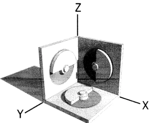
The essential simplicity o f the microgenerator allows its batch fabrication using the MEMS technology, and a number o f these generators can be arranged vertically or horizontally, as shown in figure 5, or scaled up versions can be used to meet higher power demands. This modularity also enables the use o f a multiple-axes mounting system, as shown in figure 6, to ensure power generation at any physical posture o f the patient, e.g. standing or laying down on the back or on a side.
The device can be implanted in any part o f the body, provided that it will be exposed to enough motion so as to produce sufficient pow er for the target device. In the case o f modem pacemakers, as the person increases his/her physical activity, more energy is drawn from the battery, as more pulses have to be applied to the myocardium, hence more rapidly the battery exhausts. Conversely, for a pacemaker using the proposed microgenerator an increased physical activity o f the patient would mean higher energy generation rate and power availability.
2.4 Target Application Areas
glucose-level-measurement/insulin-liberation patches and other closed-loop physiological function controllers which perform blood sampling, analysis/diagnosis and drug delivery.
In this thesis, the design o f the microgenerator will be optimized for its application in cardiac pacemakers, because the survival and long-term health o f a recipient o f one o f these implants strongly depends on the power supply capacities o f the pacemaker.
Chapter Summary
CHAPTER 3
Microgenerator Design
Supported on a b rief description o f the heart’s excitation and conduction system, this chapter explains the role o f a pacemaker as a therapeutic implant, then establishes its typical power requirements, to be met by the microgenerator, and presents the mathematical model that allows predicting the behavior o f the microgenerator and optimizing its design parameters. Two possible rotor geometries for the microgenerator are proposed to create the instability that enables the Earth’s gravitation to generate the driving torque. The selection o f magnetic material, along with the deposition, micropatteming and magnetization techniques necessary to produce the thin film alternate polarity permanent magnets in the rotor are presented. Then, a nanoparticle based lubrication system is proposed to reduce friction between movable parts in the microgenerator as a solution to lessen energy losses and extend the lifetime o f the device. Finally, simulation results for design verification are presented, as well as the design strategy employed to optimize the microgenerator for use in pacemakers and the final design specifications are summarized in a table.
3.1 Function of a Pacemaker
The heart is composed o f four major muscles: the right atrium, left atrium, right ventricle
and left ventricle, redrawn in figure 7 from [1], that make up the m yocardium ; and
During normal sinus rhythm, the heart is controlled by the SA node, which depolarizes at a rate o f 60 to 100 beats per minute. The right atrial internodal tracks and Bachmann’s bundle conduct the SA-nodal activation throughout the atria, initiating a coordinated contraction o f the atrial walls. Meanwhile, the electrical impulse transfers through the AV node that introduces a delay allowing the contraction o f the atria to complete before ventricular contraction is initiated. Then, the bundle o f His, bundle branches and Purkinje fibers conduct the electrical impulse at a high velocity while splitting the excitation throughout the two ventricles, enabling a coordinated and massive contraction [1],
Internodal Tracks
Bachm ann’s Bundle
Left atrium Bundle Branch
SA N ode Right
atrium
AV N ode
Bundle of His Left
ventricle
Right ventricle
Purkinje Fibers
Figure 7. Excitation and conduction system and major muscles in the human heart [1].
ventricular cells return to their electrical and mechanical resting state, completing the repolarization phase, which is observed as the T-wave [1].
P W ave: Atrial Depolarization
PR Interval
Figure 8. Typical electrocardiogram (ECG) and its characteristic waves [1].
Arrhythmia disorders entail the abnormal or irregular beating rhythm o f the heart due to asynchrony o f the cardiac chambers [1], negatively affecting the hemodynamic performance o f the circulatory system. The therapeutic function o f a cardiac pacemaker in the treatment o f arrhythmia is to restore the synchrony between the atria and ventricles by applying controlled electrical pulses to the heart muscles.
3.2 Design Requirements
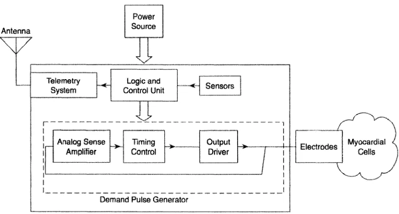
Redrawn from [1], a block diagram o f a typical cardiac pacemaker is depicted in figure 9. For effective pacing, the output pulses o f the pacemaker should have an appropriate width and frequency and sufficient energy to depolarize the myocardial cells in the vicinity o f the electrodes. On successful depolarization, the electrical stimulation will propagate from the cells surrounding the electrodes to the neighboring cells throughout the entire excitation and conduction muscular fiber system o f the heart, completing a contraction sequence.
The typical power supply specifications o f a cardiac pacemaker are listed in Table 1 [1 - 4], From Table 1, it is evident that the proposed microgenerator must generate at least 3.0 volts open circuit voltage to energize the control unit, the telemetry system and the sensors in the pacemaker, as well as to provide 3 to 6 pJ o f energy per pulse to the
Q R S Complex or R Wave: Ventricular Depolarization
ST Segment
microelectronic Demand Pulse Generator (DPG). Higher power generation may help to include additional microelectronic-based functionalities in a future pacemaker system.
Power Source Antenna
Telemetry System
Logic and
Control Unit Sensors
i--- — i
Analog Sense Amplifier
Output Driver Timing
Control
Myocardial Cells Electrodes
Demand Pulse Generator
Figure 9. Block diagram o f a typical cardiac pacemaker.
Table 1. Typical Cardiac Pacemaker Power Supply Specifications.
Parameter
Value
Unit
Battery open circuit voltage 3.0 Volts
Battery capacity 2 Ah
Pacemaker control unit voltage supply 2.2 Volts
Pacemaker control unit current drain 10 pA
Pulse duty cycle 16.7 %
Energy consumption per pulse 3-6 p j
Battery dimensions (length x width x height) 49 x 46 x 6 mm
3.3 Mathematical Model of Axial Flux Brushless Power Generators
The induced RMS voltage across the terminals o f a planar conductor coil exposed to a changing axial magnetic flux can be expressed as [9]:
Vm s = 2 p ^ N lr Q N , B S
(1)
where /? is a shape factor, Npis the number o f alternate polarity magnetic pole pairs in the rotor, N , is the number o f coil turns exposed directly to the axially changing magnetic flux, B is the remanence o f the permanent magnets and S is the area o f the planar coil covered by the pole pieces. Ignoring the fringing fields, the product J3B represents the magnetic flux density in the rotor-stator gap.
The shape factor /? as described in [10-11] determines the percentage o f flux linkage between the rotor and stator and depends on the relative thicknesses o f the permanent magnets embedded in the rotor, the planar coil and the gap between them, as shown graphically in figure 10, and is given by:
Asym m etrical rotor
Planar coil Rotor-stator gap
Figure 10. Thickness parameters used to determine the shape factor/?.
planar coil should be kept to a minimum in order to obtain a shape factor close to unity to maximize the output voltage. The angular velocity Q o f the rotor in equation (1) can be determined from the relation:
developed in this research work, where g is the acceleration due to gravity, 0 is the instantaneous angular displacement and Rp is the radius o f the rotor. The generated RMS power thus can be calculated from [9]:
where R is the total ohmic resistance o f the planar coil.
3.4 Rotor Geometry
In this thesis two possible rotor geometries for the microgenerator were investigated: a semicircular rotor geometry and a circular rotor geometry.
Semicircular Rotor Geometry - A conceptual model o f this geometry is shown in figure 11. In this approach, a number o f alternate polarity permanent magnets or pole pieces are embedded in a semicircular shaped rotor made o f a non-magnetic structural material. It is the asymmetrical shape o f the rotor that causes it to leave its initial stable position in the presence o f an external excitation. The Earth’s gravitational attraction on the rotor center o f mass, which has been displaced out o f the rotation axis, generates the actuating torque,
w h ile the m agnets em bedded in the rotor are the source o f m agnetic flux that, as the rotor
oscillates, fluctuates in direction and magnitude over the planar coils embedded in the stators, thereby inducing a voltage in them.
Gap between permanent magnets
Permanent magnet Structural material
Shaft hole
(b)
Permanent magnet
j - ShaftShaft hole
(a)
Figure 11. Semicircular rotor geometry.
(a) Top view of the semicircular rotor, (b) Cross-section view o f the semicircular rotor.
Circular Rotor Geometry - In this geometry, depicted in figure 12, an asymmetrical destabilizer body made o f a high mass density material, e.g. gold or tungsten, has been formed along a portion o f the circumference o f a circular rotor embedded with alternate polarity permanent magnets. In this configuration, it is the asymmetrical shape o f the destabilizer what displaces the center o f mass out o f the rotation axis, enabling the Earth’s gravitation to generate the actuating torque. The major advantage o f this geometry is that the entire area o f the planar coils embedded in the stators is exposed to the changing magnetic flux created by the mechanical oscillation o f the rotor, fact that contributing to a higher power generation.
Destabilizer
Circular rotor
Permanent magnet
/ —Shaft hole
Ivmva
Destabilizer
Shaft hole
- Permanent magnet
Structural material
(b)
Gap between permanent magnets
(a)
The fabrication process o f a microgenerator with a semicircular rotor will require fewer process steps and materials than a microgenerator that incorporates a circular rotor, hence the later will be more expensive. A semicircular rotor microgenerator occupies a smaller volume, however it cannot reach the energy generation capability o f a circular rotor microgenerator. Additionally, in the circular rotor geometry the magnitude o f the actuating torque, exerted by the Earth’s gravitation on the rotor, can be controlled by changing the radius, thickness and material o f the destabilizer independently o f the dimensions or material o f the rotor and permanent magnets.
3.5 Magnetic Material Selection
Investigation shows that the high coercivity Nd2Fei4B (abbreviated NdFeB) crystalline
o f NdFeB thin films, the micromagnets in the rotor are to be immediately coated with a protective layer before being exposed to air and to the strong etchants used to pattern other materials during the fabrication process.
3.6 Magnetization of NdFeB Magnets
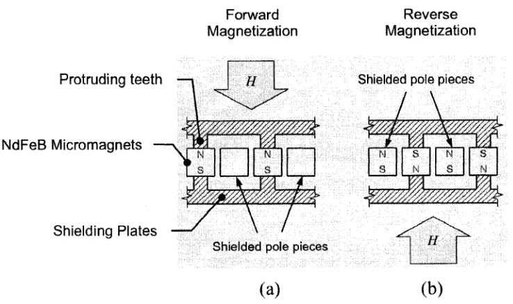
A major design challenge to realize the MEMS microgenerator appears to be the alternate polarity magnetization o f the deposited and patterned NdFeB thin film magnetic pole pieces embedded in the rotor. Although a number o f different methods for alternate polarity magnetization are available [40-43], it appears that none o f the methods is suitable for the microgenerator due to microsized dimensions and micrometer scale proximity o f the pole pieces. After investigation, the author has developed a novel method o f alternate polarity magnetization o f very close proximity thin film magnets. The capacitor discharge magnetization circuit used for the developed Magnetic Flux Shielding Selective Magnetization (MFSSM) method is illustrated in figure 13. As shown in figure 13, in the magnetizing fixture two identical high-permeability (nickel, Permalloy®, MU-metal®) shielding plates with protruding teeth are placed above and below the set o f thin film magnets to be magnetized. Then, the stack o f shielding plates and magnets is secured between the poles o f a commercial capacitor discharge magnetizer.
NdFeB micromagnets Shielding
plates
Protruding teeth Power
supply
--- Magnetizing fixture Capacitor Discharge Magnetizer
The two stages o f the MFSSM method are depicted in figure 14. During forward magnetization, the magnetizing field H generated by the capacitor discharge magnetizer is directed towards the selected pole pieces by aligning them with the protruding teeth of the shielding plates. As a result a high permeability magnetic path is established through these pole pieces, whereas the pole pieces in between the aligned ones are placed in a low permeability magnetic path, i.e. they become shielded. Thus, when applying the magnetizing field in the first stage (figure 14a), the shielded pole pieces do not reach the magnetization saturation point o f the material and remain unmagnetized when the field is withdrawn. In the second stage (figure 14b), the direction o f the magnetizing field H is reversed while the protruding teeth o f the shielding plates are aligned with the pole pieces that were shielded in the first stage. As a result, the pole pieces now in the high permeability magnetic path are magnetized in the reverse polarity and the magnetizing force through the shielded ones is not strong enough to switch their previously established polarity as they feature a high coercivity property.
Forward M agnetization
R e v e r s e M agn etization
Protruding teeth
N d F eB M icrom agn ets
Sh ield in g P la te s
Shielded pole pieces
(a)
Shielded pole pieces
N S ■ j ^
s
*
N S'//M
s N*
(b)
Figure 14. Stages o f the MFSSM magnetization method.
(a) First stage - forward magnetization, (b) Second stage - reverse magnetization.
simulation, as shown in figure 15, a set o f three unmagnetized NdFeB thin film pole pieces are placed next to each other on the same plane and separated by an airgap.
Figure 15. 3D Model used for simulation o f the MFSSM magnetization method.
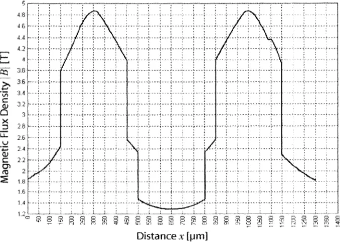
The shielding plates are placed on top and bottom o f the magnet array, with their teeth touching the two NdFeB thin film pole pieces at the extremes. For more efficient meshing and shorter simulation time, the rotor structural material and the protective coating o f the NdFeB thin film pole pieces were not included in the simulation. The model was then exposed to a constant and uniform magnetizing field produced by an infinitely long solenoid that plays the role o f the actual capacitor discharge magnetizer. From the results o f simulation, shown in figures 16 and 17, it is evident that most o f the magnetic flux is confined within the magnetic path passing through the NdFeB thin film pole pieces at the extremes, while just a few flux lines cross through the NdFeB thin film piece in the center, i.e. the magnet in the center is being shielded from the magnetizing field. Figure 17 is a plot o f the magnetic flux densities measured in a horizontal line that intersects the three micromagnets through the center. The peaks correspond to the magnetic flux density at the interior o f the micromagnets on the extremes and the valley corresponds to the magnetic flux density in the shielded magnet. From figure 17, it can be seen that the magnets at the extremes receive a magnetizing force approximately five times greater compared to the shielded magnet. As a result, the magnets on the extremes will reach saturation earlier compared to the shielded magnet and will be the only ones in attaining a permanent magnet characteristic after turning o ff the magnetizing field. These
High permeability shielding plates
simulation results establish the validity o f the developed MFSSM magnetization method that is to be used for alternate polarity magnetization o f the permanent magnets embedded in the rotor o f the microgenerator.
Figure 16. Simulation results o f magnetic flux density in the MFSSM method.
2 6
CT>
.
-1.2
D istance* [pm]
3.7 Lubrication System
As the rotor oscillates around the central shaft, the friction at the interface between them, as shown in figures 18 and 19, will unavoidably wear these bodies and will produce losses due to frictional forces opposing to the movement o f the rotor. If the rotor was made o f a soft material, e.g. SU-8 (as used in [9]) and the shaft was fabricated o f a hard material, like polysilicon, the rotor would wear very fast if no bearing or lubrication mechanism is incorporated to the system. Additionally, due to the small mass o f the rotor, the magnitude o f the frictional force may surpass the gravitational torque that causes the rotor to oscillate, thus preventing the rotor from moving or from reaching maximum angular velocity. However, if friction is controlled properly, energy losses can be reduced to allow satisfactory operation o f the device and wear can be minimized to a point that the life span of the generator extends for the term o f years. With this purpose a suitable lubrication mechanism must be incorporated in the system. The lubrication system of choice must meet the conditions o f micro-scale manufacturability and batch fabrication capability. Furthermore, its tribological properties must remain the same during the anticipated life span o f the microgenerator and it must not interfere with the magnetic/electric circuits in the microgenerator.
Semicircular rotor
Shaft
Semicircular rotor
Shaft
Interface
(a)
Destabilizer
Circular rotor Destabilizer
•Shaft - Circular rotor
y^Shaft
Interface
(a)
Figure 19. Detail of the interface between a circular rotor and the shaft. (a) Top view of the circular rotor, (b) Cross-section view o f the circular rotor.
Thin air film hydrodynamic lubrication systems, as used in [10-11], appear not to be suitable for the proposed microgenerator, as the low relative velocity between sliding surfaces o f the shaft and the rotor does not allow the formation o f an air film capable to keep separation between them, and also because the microgenerator is to be vacuum- sealed in order to minimize mechanical damping o f the rotor. Conventional oil or silicone lubricants cannot be used either as their tribological properties are highly dependant on temperature, in vacuum they volatilize away, their surface tension and viscosity may be high enough to clog the rotor and the lubricant itself could be a source o f contamination if leakage occurs through microscopic cracks in the walls o f the microgenerator.
MEMS because a number o f them can be deposited using standard microfabrication techniques, like chemical vapor deposition (CVD), epitaxial growth or electroplating [47], Some most prominent solid lubricant films are those made o f super-hard materials, like synthetic diamond or carbides containing tungsten, silicon, aluminum or titanium; also soft metallic films like TiN, silver and thick plasma-sprayed layers o f chromia- molybdenum, zirconia-alumina and alumina-titania; self-assembled monolayers (SAMs) o f methylated fluorocarbon and other organic compounds; thin films or powder o f graphite, molybdenum disulfide or Molybdenite (M0S2) and tungsten disulfide or
Tungstenite (WS2).
The major advantage o f solid lubricants is that they can provide effective lubrication while eliminating the strong surface tension and high viscosity o f liquid phase oil-based or silicone-based lubricants. Solid lubricants are also well suited for low speed or vacuum applications, where hydrodynamic lubrication cannot be created. These features make solid lubricants a suitable solution to reduce friction in the presented microgenerator. An clcctroless deposited Ni-P-(IF-W S2) composite solid lubricant film presented by [48] consisting o f a suspension o f inorganic Fullerene-like tungsten disulfide nanoparticles (IF-WS2) aggregated to a nickel-phosphorus (Ni-P) alloy was developed and tested to
compare its tribological performance with other Ni-P based solid lubricant films already being used as wear-resistant coatings. The IF-W S2 nanoparticles, synthesized through the
method described by [49], range in size from 100 nm to 200 nm and even though they are not perfect spheres, have a very definite boundary, which is the consequence o f their multilayer closed crystalline structure that, differently from amorphous W S2 nanoparticles, enables them to roll and slide.
The experiments to determine wear and friction coefficient o f the different Ni-P films tested by [48] yield the results shown in Table 2. From Table 2, it is evident that the Ni- P-(IF-W S2) film possesses considerably better tribological properties than other Ni-P
Table 2. Wear and Friction Coefficient o f different Ni-P thin films [48].
Thin Film
Mass loss of block (mg)
Friction Coefficient
Ni-P 15.6 0.090
Ni-P-(2H-W S2) 5.2 0.062
Ni-P-Graphite 4.3 0.067
Ni-P-(IF-W S2) 3.0 0.030
According to [48-49] and [52], the favorable tribological properties o f the N i-P-(lF-W S2)
film are due to the ability of IF-WS2 nanoparticles to roll/slide between interfacing
surfaces; also, during friction, they are slowly released from the Ni-P alloy, providing continuous replenishing o f lubricant material; they serve as spacers, preventing contact between asperities; they can fill up very small pores, contributing to reduce surface roughness; they associate with the wear particles and facilitate them to slide past the contact area, limiting abrasive wear; some particles exfoliate, yielding one-atom thick sheets o f hexagonal crystalline structure that locally produce a superlubricity effect, also observed in graphite [50-51]. A conceptual 3D model o f the N i-P-(lF-W S2) solid
lubricant film is depicted in figure 20.
IF-WS2 n anoparticles
-Ni-P alloy
As can be seen from figure 20, some nanoparticles move freely on the surface o f the film while the rest, to be released along time due to friction, is trapped in the Ni-P alloy.
Due to the good experimental performance o f the Ni-P-(IF-W S2) film, its ability to be
integrated to a batch fabrication process, as it can be electroless deposited, and considering the complexities o f implementing micro ball bearings, micro sliders and other solid or liquid lubricants, a thin coating o f Ni-P-(IF-W S2) around the central shaft
was selected as the lubrication system to minimize wear and energy losses due to friction between interfacing surfaces o f the shaft and the rotor in the microgenerator system.
3.8 Design Strategy and Final Device Specifications
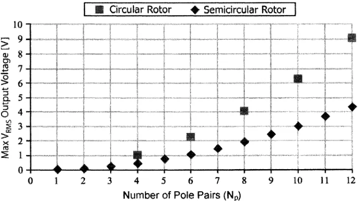
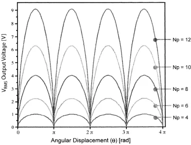
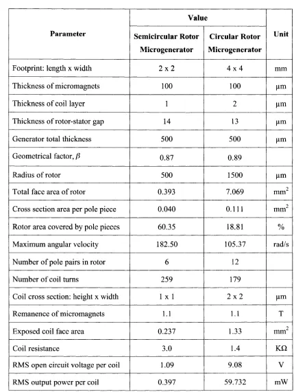
Following equation (1), the major design objective is to minimize the overall volume o f the microgenerator while optimizing the rotor size to increase the exposed face area S.
![Figure 1. Three types of electromagnetic induction microgenerators [17]. (a) Rotational generators, (b) Oscillatory generators, (c) Hybrid generators.](https://thumb-us.123doks.com/thumbv2/123dok_us/1473909.1180497/18.614.236.419.91.637/electromagnetic-induction-microgenerators-rotational-generators-oscillatory-generators-generators.webp)