www.ijiset.com
159
Analysis of Fuzzy Control of Dynamic Loads
with Adaptive Power System
Pankaj Kumar Verma
P#
P
, Anupam Masih
P*
P
#
P
Electrical Engineering, Sam Higginbottom University of Agriculture Technology and Sciences Allahabad, Uttar Pradesh India.
*Assistant Professor, Dept. of Electrical Engineering, SIET, SHUATS, Allahabad, Uttar Pradesh, India
ABSTRACT- In this paper proposes an Adaptive Power System (APS), it is utilized to alleviate the negative effects exhibit on the stages coming about because of vast dynamic burdens. Here we are utilizing the fluffy rationale controller, since it has many preferences contrasting with different controllers. For example, the fluffy controller is the most reasonable for the human basic leadership instrument, giving the operation of an electronic framework with choices of specialists. The Navy's future and close term high-vitality sensors and high-vitality weapons will expend a huge segment of the assets of the expected ship stage. By utilizing the fluffy controller for a nonlinear framework takes into account a decrease of unverifiable impacts in the framework control and enhances the proficiency. The APS has used to look after generator/prime-mover unwavering quality, and furthermore it is utilized to enhance sensor/weapon execution or enhance measurements, for example, framework weight, cooling requests, and ship filling costs. By utilizing the reenactment comes about we can examine the proposed strategy.
1. INTRODUCTION
The APS is like the dynamic channel idea whereby the dynamic channel gives the current expected to keep up the nature of the heap current required by the upstream power framework. Obligation cycles can change from little to nonstop and, for a few cases, the pinnacle control requests can be over the capacity of the ship control plant.
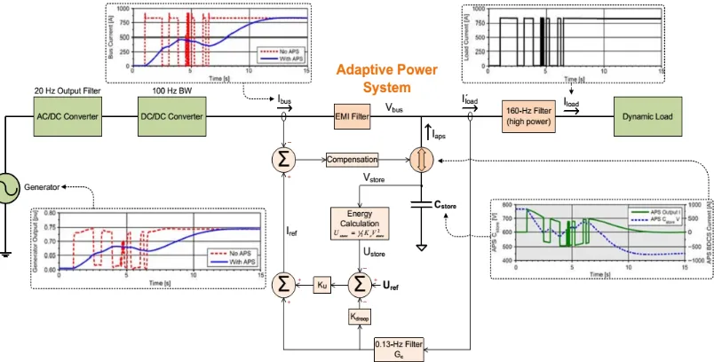
The Adaptive Power System (APS) idea introduced in this paper can be an empowering innovation for sensors or weapons with expansive dynamic burdens, which without the APS would be incongruent with the upstream shipboard generator and circulation transport. The APS comprises of vitality stockpiling, a bidirectional current source, and imaginative control methods. These inventive control methods increment the vitality stockpiling use, subsequently limiting the vitality stockpiling size. A square chart of a traditional shipboard power framework is appeared in the Figure 1. Ordinary frameworks have concentrated vigorously on giving all around managed voltages and clean energy to the comparing load. On the off chance that the voltage flow seen at the heap are to be limited, the yield impedance of every converter organize is limited by utilizing little arrangement inductance esteems,
substantial shunt capacitance esteems, and control circles with high transmission capacities. In any case, to keep the mid to low recurrence stack flow this sort of framework is introduced from proliferating back to the circulation transport and generator.
At the point when contrasted and the inactive channel strategy (beast drive technique) the APS can bolster the beat stack at a small amount of the size and weight required. In the event that utilizing the dynamic load technique without inordinate power dissemination as would exist (discard strategy), and for some particular applications without timetable limitations as would be required if utilizing an invigorate or energizing sort framework (confined course of events technique).
Fig. 1. A block diagram of a notional power system with the APS attached
As far as possible for the upgraded operation is constrained by the APS measure, the extent of the vitality stockpiling expected to give the delta control, and the most extreme normal power permitted. This most extreme permitted normal power decides the comparing obligation cycle of this upgraded operation and subsequently the speediest permitted revive time of the APS vitality stockpiling. Therefore, another approach is expected to deal with the heap progression of developing Navy frameworks.
www.ijiset.com
160
APS comprises of vitality stockpiling, a detached power channel, a bi-directional current source, and imaginative control circles, as appeared in Figure 2. The bi-directional current source proficiently conveys the beat control request from the APS vitality stockpiling to the coveted sensor or weapon framework, therefore giving a support to the upstream power gear.
The APS is like the dynamic channel idea whereby the dynamic channel gives the current expected to keep up the nature of the heap current required by the upstream power framework. Dynamic channels have been utilized for quite a long time in rotating current (AC) control frameworks to diminish the present music and enhance the power factor exhibited to the source when the heaps are nonlinear and electrically boisterous.
Fig. 2. An overview of the functionality of the APS system.
With the best possible utilization of control circles and vitality stockpiling, the APS can diminish the rate at which the power request on the generator changes, subsequently restricting the flow and ghastly substance seen by the generator - changing a weapon or sensor framework that had generally been inconsistent with the state’s energy framework into one that is presently plausible.
2. ADAPTIVE POWER S YSTEM (APS) 2.1 Overview
The objective of the APS is to limit transport unsettling influences and worry to prime-control hardware by changing over the dynamic power stack into a proportional moving normal of the power request. The APS is intended to meet the proposed prerequisite as appeared in Figure 3.
Fig. 3. The power ripple filtering requirement of the APS
The APS execution should likewise not meddle with keeping up a hardened voltage (firmly directed voltage) to the heap. The best level segments of the APS incorporate the vitality stockpiling capacitance and two control circles. One circle controls the APS yield current to give the required dynamic current to the heap utilizing the vitality from the capacity capacitance, and the other circle keeps up the voltage over the vitality stockpiling capacitance to inside the permitted rating.
Figure 2 gives the detail voltage and current waveforms for the APS and the generator control waveform amid the use of a dynamic load profile. 2.2 Operation of the Adaptive Power System is as follows:
www.ijiset.com
161
• Hence, the AC segment or elements of the heap profile isn't a piece of Ibus yet is given by the vitality stockpiling capacitance through the BDCS.
• The vitality stockpiling capacitance esteem is chosen to be sufficiently huge to give the source and sink streams to help the beat stack request. The incentive for the vitality stockpiling capacitance is limited by enabling the voltage crosswise over Cstore to differ essentially, where Udelivered = 1 2 Cstore(Vt20 − Vt2+), limiting the vitality stockpiling capacitance required.
– This gives huge weight and size investment funds contrasted with utilizing an in-line powerful low-pass channel (animal power technique).
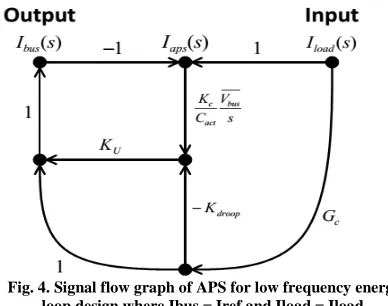
Fig. 4. Signal flow graph of APS for low frequency energy loop design where Ibus = Iref and Iload = Iload.
– The voltage variation across Cstore is also decoupled from the load, allowing tight regulation of the bus voltage seen by the load to be maintained. Udelivered is the energy delivered or absorbed by the storage capacitance, and Vt0 and Vt+ are the corresponding voltages across the energy-storage capacitance just prior to the load disturbance and after the energy-storage capacitance has delivered or absorbed the desired energy.
2.3 APS Requirements for Notional System
To demonstrate the APS functionality and performance, a top-level design and simulation for a notional 300-kW system was performed. For this specific system the APS interfaces with the 375-VDC bus, as shown in Figure 1. The system was designed to support the following load and input–output performance specifications:
• Duty Cycle of Load: 0 to continuous • Average Load Power: 0 to 300 kW • Peak Load Power: 0 to 300 kW
• Input Voltage: 4160 VAC per MIL-STD-1399-680 • Input Interface Power Ripple Requirements: Figure 3
• Voltage Transients at the 375-V Bus Load Interface: maintain to better than ±5%
2.4 APS Design Details for Notional System Control Loop Bandwidth Considerations:
Figure 5 provides the schematic details for the APS. The bi-directional current source is a modular design consisting of thirty-eight 8-kW modules.
The sizing and performance for the BDCS is based on the bi-directional buck topology [17], using a 100-kHz switching frequency and average current-mode control. The switching frequency is chosen high enough to obtain the needed control loop bandwidths (which will give the desired APS filtering performance) but low enough to maintain acceptable switching losses. The inner current loop bandwidth of the bi-directional current source is set to be between 15 and 25 kHz (varies with the voltage across Cstore), allowing the outer current loop of the APS to be set at 4 kHz.
To simplify the analysis, the preceding assumptions have been used, and therefore this signal flow graph is only valid for low frequencies. In Figure 4, Ibus is the controlled upstream bus current coming from the 375-V converter, Iload is the current to the load before the 160-Hz filter, and Gc is the transfer function of the 0.13-Hz filter, which has been selected to be a second order filter defined as
𝐺𝑐= 𝜔𝑐
2
𝑠2+(2(𝜔𝑐)𝑠)+𝜔𝑐2 (1)
where ω c is the corner frequency (in rad/s) and ζ is the damping ratio. In this example, ζ is equal to 0.9.
In addition, Ku is the energy-loop gain that determines the energy outer loop bandwidth, Kdroop is the gain of the energy droop compensation (in J/A), Cact is the actual capacitance of Cstore (in Farads), and Kc is the capacitance value (in Farads) used in converting the measured capacitor bank voltage, Vstore, to energy,
the transfer function can be determined as follows:
𝐼𝑏𝑢𝑠(𝑠)
𝐼𝑙𝑜𝑎𝑑(𝑆)= ∑
𝑃𝑘∆𝑘
∆ 𝑁
𝑘=1 (2)
where N is the total number of forward paths, Pk is the gain of the kth forward path, Δ is the determinant, and Δk is the cofactor of path k. The gain of forward paths are defined as
𝑃1= 𝐺𝑐, (3)
𝑃2= −𝑘𝑑𝑟𝑜𝑜𝑝𝐾𝑈𝐺𝐶, (4)
𝑃3= 𝑘𝑢𝑐𝑘𝑎𝑐𝑡𝐶 𝑉�������𝑏𝑢𝑠𝑠 , (5)
www.ijiset.com
162
𝐿 = −𝑘𝑢𝑐𝑘𝑎𝑐𝑡𝐶 𝑉�������𝑏𝑢𝑠𝑠 , (6)Fig. 5. The high-level schematic of an APS system used for simulation, where N is the total number of parallel modules (N=)38
The determinant is then
∆= 1 − 𝐿 = 1 + 𝑘𝑢𝑐𝑘𝑎𝑐𝑡𝐶 𝑉�������𝑏𝑢𝑠𝑠 (7)
Because the loop, L, touches all the forward paths, the cofactor for each forward path is simplify defined by
∆1= ∆2= ∆3= 1 (8)
Fig. 6. The bus current filtering performance of the APS with the proposed requirement overlaid (for example, a 100 kW average load is allowed 3 kW peak ripple at 1 Hz). Because the bus voltage is approximately constant, current filtering directly
relates to power filtering.
Figure 6 demonstrates that this equation’s predictions (black dashed line) are nearly identical to the detailed simulation results (solid blue line) up to 4 Hz, at which point interactions with the current control-loop compensator begins to appear. Figure 6 provides the time-constant requirement via the frequency-domain specification needed to determine the storage-capacitance nominal value, Cdesign.
This results since K droop’s units are Joules/Ampere. Knowing the amount of energy used,
𝑈𝑡𝑜𝑡𝑎𝑙= 𝐼𝑙𝑜𝑎𝑑𝑚𝑎𝑥𝐾𝑑𝑟𝑜𝑜𝑝 (9)
along with the maximum available energy for use
𝑈𝑚𝑎𝑥=12𝐶𝑑𝑒𝑠𝑖𝑔𝑛(𝑉𝑚𝑎𝑥2 − 𝑉𝑚𝑖𝑛2 ) (10)
the corresponding capacitance value can be solved for
𝐶𝑑𝑒𝑠𝑖𝑔𝑛 =2𝐼𝑙𝑜𝑎𝑑𝑚𝑎𝑥�𝑉 𝐾𝑑𝑟𝑜𝑜𝑝
𝑚𝑎𝑥2 −𝑉𝑚𝑖𝑛2 � (11)
Here, Iloadmax is the designed maximum load current of the module, Vmax is the maximum allowed capacitor voltage, Vmin is the minimum allowed capacitor voltage.
Table I provides a summary of predicted component losses. The MOSFETs used in the implementation of the BDCS are silicon carbide devices. Silicon carbide devices are selected because of the inherently low drain to source parasitic capacitance, which is crucial to minimizing the switching losses when operating at the high voltage levels with hard switching.
TABLE I
POWERLOSSES OF THEAPS SYSTEM
www.ijiset.com
163
The Navy's MIL-STD-1399-680 tends to beat stacking prerequisites, however just manages beats that happen occasionally – not exactly once at regular intervals. A prerequisite is required that secures the genset and appropriation transport against the progression coming about because of regular and monotonous beating loads however which isn't as prohibitive as the present necessity of just permitting a solitary heartbeat once like clockwork. Meeting the accompanying prerequisite would give this insurance, and with the utilization of the APS, this necessity is achievable to actualize, notwithstanding for frameworks with expansive dynamic power profiles. 3.1 Proposed Pulsed Load Requirement:
The consolidated three-stage crest control swell as observed by the shipboard generator(s) at any single recurrence created by the heap should be not as much as the cutoff points characterized by Figure 3. The subsequent permitted stack profile proposed in Figure 3 has been coordinated to the generator and prime mover execution. Run of the mill gensets' reaction times to a critical load change are on the request of 1.0 to 1.5 sec [15], [16]. In the event that the ascent and fall times for control changes (incline rate) seen by the generator are controlled to be slower than the genset's reaction times, the generator and prime-mover control circles will have the capacity to keep up the voltage and speed direction, transport aggravations will be kept to a base for such a moderate changing force profile, and sub-synchronous resonances won't be energized in light of the fact that the unsettling influences are at bring down frequencies.
4. FUZZY LOGIC CONTROLLER
In FLC, basic control action is determined by a set of linguistic rules. These rules are determined by the system. Since the numerical variables are converted into linguistic variables, mathematical modeling of the system is not required in FC.
Fig.7.Fuzzy logic controller
The FLC comprises of three parts: fuzzification, interference engine and defuzzification. The FC is characterized as i. seven fuzzy sets for each input and output. ii. Triangular membership functions for simplicity. iii. Fuzzification using continuous universe of discourse. iv. Implication
using Mamdani’s, ‘min’ operator. v. Defuzzification using the height method.
Fuzzification: Membership function values are assigned to the linguistic variables, using seven fuzzy subsets: NB (Negative Big), NM (Negative Medium), NS (Negative Small), ZE (Zero), PS (Positive Small), PM (Positive Medium), and PB (Positive Big). The Partition of fuzzy subsets and the shape of membership CE(k) E(k) function adapt the shape up to appropriate system. The value of input error and change in error are normalized by an input scaling factor.In this system the input scaling factor has been designed such that input values are between -1 and +1. The triangular shape of the membership function of this arrangement presumes that for any particular E(k) input there is only one dominant fuzzy subset. The input error for the FLC is given as
E(k) = Pph(k)−Pph(k−1)
Vph(k)−Vph(k−1) (12)
CE(k) = E(k) – E(k-1) (13)
Inference Method: Several composition methods such as Max–Min and Max-Dot have been proposed in the literature. In this paper Min method is used. The output membership function of each rule is given by the minimum operator and maximum operator. Table 1 shows rule base of the FLC.
Defuzzification: As a plant usually requires a non-fuzzy value of control, a defuzzification stage is needed. To compute the output of the FLC, „height‟ method is used and the FLC output modifies the control output. Further, the output of FLC controls the switch in the inverter. In UPQC, the active power, reactive power, terminal voltage of the line and capacitor voltage are required to be maintained. In order to control these parameters, they are sensed and compared with the reference values. To achieve this, the membership functions of FC are: error, change in error and output
The set of FC rules are derived from
u=-[α E + (1-α)*C] (14)
www.ijiset.com
164
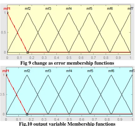
Fig 9 change as error membership functions
Fig.10 output variable Membership functions
Where α is self-adjustable factor which can regulate the whole operation. E is the error of the system, C is the change in error and u is the control variable.
Fig11. Block diagram of simulation
Fig 12. Control block diagram of simulation
Fig13. Block diagram of fuzzy logic controller
5. Simulation results for Notional System
The DC/DC converter voltage control loop is set at 100 Hz. To demonstrate the effectiveness and benefits of the APS, Figures 14(a) and 14(b) provide simulation results for various waveforms in the system when a dynamic load is applied both with and without use of the APS.
The load profile chosen in Figures 14(a) and 14(b) not only contains varying duty cycles but also simulates the extreme stressing condition.
(a)Load and APS results.
(b)Generator results.
Fig. 14. Simulation results of the first load profile.
Figure11(a) also shows the voltage waveform of the storage capacitor and the current waveform of the bi-directional current source, demonstrating the APS’s capability of providing the dynamic demand of the load resulting in the generator only having to provide the rolling average of the load power profile.
6. CONCLUSION
www.ijiset.com
165
energizing expenses. By utilizing the fluffy controller for a nonlinear framework takes into consideration a diminishment of questionable impacts in the framework control and enhances the proficiency. The APS configuration is displayed alongside reenactment comes about checking the idea. By utilizing the reenactment comes about we can investigate the proposed strategy.
REFERENCES
[1] F. Kanellos, I. Hatzilau, and J. Prousalidis, “Investigation of voltage/frequency modulation in ship electric networks with pulsed loads according to stanag 1008 design constraints,” in All Electric Ship Conference, 2007.
[2] IEEE Recommended Practices and Requirements for Harmonic Control in Electrical Power Systems, IEEE Industry Applications Society/Power Engineering Society Std. 519-1992, 1993.
[3] M. Baldwin, “Electric arc furnace impact on generator torque,” in Power Systems Conference and Exposition, 2004. IEEE PES, 2004, pp. 776– 780 vol.2.
[4] G. J. Tsekouras, F. D. Kanellos, J. M. Prousalidis, and I. K. Hatzilau, “Stanag 1008 design constraints for pulsed loads in the frame of the all electric ship concept,” Nausivios Chora, vol. 3, pp. 113–152, 2010. [Online]. Available: http://nausivios.snd.edu.gr/nausivios/docs/b3 2010. pdf
[5] H. Smolleck, S. Ranade, N. R. Prasad, and R. Velasco, “Effects of pulsed-power loads upon an electric power grid,” Power Delivery, IEEE Transactions on, vol. 6, no. 4, pp. 1629–1640, Oct 1991.
[6] D. N. Walker, S. L. Adams, and R. J. Placek, “Torsional vibration and fatigue of turbine-generator shafts,” Power Apparatus and Systems, IEEE Transactions on, vol. PAS-100, no. 11, pp. 4373– 4380, 1981.
[7] M. Butler, G. Dakermanji, L. Goliaszewski, D. Kusnierkiewicz, J. Tarr, D. Temkin, and U. Carlsson, “Fault tolerant shunt regulator for a spacecraft thermionic nuclear reactor,” AIP Conference Proceedings, vol. 324, no. 1, pp. 39–44, 1995. [Online]. Available: http: //scitation.aip.org/content/aip/proceeding/aipcp/10.1
063/1.47196
[8] M. Doyle, D. Samuel, T. Conway, and R. Klimowski, “Electromagnetic aircraft launch
system-emals,” Magnetics, IEEE Transactions on, vol. 31, no. 1, pp. 528–533, Jan 1995.
[9] J. Bernardes, M. Stumborg, and T. Jean, “Analysis of a capacitor-based pulsed-power system for driving long-range electromagnetic guns,” Magnetics, IEEE Transactions on, vol. 39, no. 1, pp. 486–490, Jan 2003.
[10] B. Singh, K. Al-Haddad, and A. Chandra, “A review of active filters for power quality improvement,” Industrial Electronics, IEEE Transactions on, vol. 46, no. 5, pp. 960–971, Oct 1999.
Pankaj Kumar Verma
received the B.Tech degree in Electrical and Electronics Engineering from Alice Institute of Technology, Ranchi, Jharkhand India, and
currently he is a post graduate
student pursuing M.Tech in Electrical
Engineering (Power System) from Sam
Higginbottom University of Agriculture Technology and Sciences Allahabad, Uttar Pradesh India. His main research interests include Electrical Engineering (Power System) and He is currently doing his project in Power Electronics.