Auto Angular Tracking of UAV Based on Mixed
Phased/Retrodirective Array
Alaa Salman*, Shokri Almekdad, and Mohamad Alhariri
Abstract—A mixed phased array and retrodirective array providing auto tracking of the angular position of the unmanned aerial vehicle (UAV) is presented. The phase conjugation technique and complex vector multiplication are used together to find the geometric phase of each channel canceling the need to use direction finding algorithm (DOA). After generating the phase conjugated version of the received signal on each channel, its complex vector representation will be multiplied by the complex vector representation of the received signal on the reference channel. The UAV will stay on the beak of the array factor during its movement within the field of view (FOV), and a permanent high gain data link is obtained without the need of the tracking algorithm. The beamwidth of the resulted array is widened to be equal to the FOV. The computational cost of the tracking system will be reduced due to canceling the need of using the complex processing algorithms (DOA, and tracking) used in smart antenna. Direction finding algorithm, beamforming algorithm, and tracking algorithm are combined in one algorithm. The least square error pattern synthesis with nulls method is used to eliminate the predefined interference signals and add null steering ability to the resulted array. The effect of the phase errors is reduced to the case of single antenna due to including the phase errors of each channel in its complex weights. The beam pointing error is taken as a metric to evaluate the performance of the resulted array compared with the BPE of a phased array using the monopulse tracking method.
1. INTRODUCTION
Unmanned aerial vehicle (UAV) has a variety of communication links with different types and characteristics to accomplish its mission tasks [1–3]. UAV is equipped with stabilized camera payload to achieve the intelligence and surveillance missions, thus the payload imagery and flight progress down-links are clearly essential for accomplishment of the UAV mission tasks. The mission has to be aborted in case of payload (camera) down-link loss [2]. The antenna of the ground control station (GCS) must have a narrow, precisely directed beam towards the UAV [2, 3] to get a permanent high gain data link between the UAV and the GCS and to receive all the signals sent by the UAV [1–3, 5, 6]. In other words, achieving high gain data link requires applying direction of arrival (DOA) algorithm to determine the direction of the UAV then applying tracking algorithm to keep the UAV within the main lobe of the antenna and getting a high gain data link.
Phased array is recently used in the GCS to achieve fast tracking and to avoid the problems of the mechanical movement of the antenna in the traditional systems [4–6]. The scenario of achieving this mission with phased array is as follows: acquiring the signal sent from the UAV and determining the UAV angular position using DOA algorithm like MUSIC algorithm [9, 10] or RSNS algorithm [4, 5], then forming the beam towards the UAV to receive the signal in maximum gain using beamforming algorithm [7, 8], and finally tracking the UAV angular position using tracking algorithm like monopulse
Received 25 January 2019, Accepted 30 April 2019, Scheduled 15 May 2019
* Corresponding author: Alaa Salman ([email protected]).
tracking algorithm [4, 5]. These algorithms increase the computational cost of the phased array system [7–12], and on the other hand, these algorithms require high calibration of the array [6, 7]. In addition, using the phased array results in increased sources of noise [13–15], where the phased array is sensitive to phase errors caused by random phase noise, quadrature modulation demodulation errors, and element dislocation [14]. Phase error’s effect on the pattern can include loss in gain, increased sidelobe levels, and increased beam pointing errors (BPE) [15–19].
The main function of the tacking array is to keep the UAV within the main beam during its movement within the field of view (FOV), so widening the beamwidth of the antenna array is good for keeping the UAV within the main beam of the array, but it will be at the expense of reducing the gain and increasing the possibility of receiving interference signals, which may lead to the failure in achieving the desired link.
This paper presents a new structure of tracking array that has the ability to achieve auto forming of the reception beam towards the angular position of the UAV without the need of complex signal processing algorithms used in smart antenna. The proposed structure makes mixing between phased array and retrodirective array [20–24], where the phase conjugation technique and complex vector multiplication are used together to generate the geometric phase of each channel. The resulting array gives a permanent high gain downlink between the UAV and the GCS, so widening the beamwidth to be equal to the FOV without reducing the gain and with null steering ability to eliminate the predefined interference signal. In the resulting array, the effect of phase errors is reduced to the case of single antenna receiver.
In this paper, we use the beam pointing error (BPE) as a metric to evaluate the performance of the resulting array, where we will compare the BPE of the resulting array with the BPE of a phased array using the monopulse tracking method.
In the following sections, we will present the methodology of the proposed approach and illustrate the block diagram, then we will mathematically illustrate how to reduce the effect of the phase errors and widen the beamwidth with null steering ability, then the simulation and results followed by the conclusion.
2. METHODOLOGY
2.1. Block Diagram
Figure 1 shows the block diagram of the proposed structure of the tracking array, and we take two channels for simplicity.
( )t (wRFt n)
x =cos +φ
(wIFt−φn) cos
(wIFm−φn) cos
n j n e
r = φ
(
wRFt+φref)
cos
(
wIFm−φref)
cos
ref
j ref e
r = φ
(wLOt) cos
IF RF LO w w
w = −
(
2wIFm)
cosn
j
n e
r* = −φ
(wIFm+φn) cos
(
wIFt−φref)
cos
gn j n e
c = −φ
ref j eφ ref
j eφ
(
wIFm)
cosFigure 1. Block diagram of two channels of the tracking array.
Due to using the quadrature demodulation in the receiver, the received signal can be represented in a complex form as in Eq. (1)
S=ej∅ (1)
where ∅ is the phase of the received signal. In antenna array the received signal on each channel is
the phase shifted version of the received signal on the reference channel by the geometric phase of each channel [11, 12]. By considering the first channel as the reference channel, the complex vector representation of the received signal on the reference channel can be represented in the complex form as in Eq. (2):
rref =ej∅ref =S (2)
where ∅ref is the phase of the received signal on the reference channel. Also the complex vector
representation of the received signal on each other channel will be:
rn=ej(∅ref+∅gn) =ej∅n (3) wherenis the channel number,∅gnthe geometric phase of each channel, and∅nthe phase of the received
signal on each channel. The geometric phase of each channel is related to the angle of arrival θi of the received signal and the geometric of the array elements, as in Eq. (4) for the uniform linear array case:
∅gn =
2πn
λ dsin (θi) (4)
Then the received signals at the output of the array channels can be represented by the matrix shown in Eq. (5)
V =
ej∅refej(∅ref+∅g1)ej(∅ref+∅g2). . . ej(∅ref+∅gN−1) (5)
where N is the number of the array elements. The beamformer in the digital phased array can be
so the phase shift will be compensated, and the signals will add constructively. The complex weight at the output of each channel is like Eq. (6):
w∗n=e−j∅gn =e−j
2πn
λ dsin(θi) (6)
The complex weights can be represented by the matrix shown in Eq. (7):
WH =
ej0e−j∅g1e−j∅g2 . . . e−j∅gN−1 (7)
The array response at the output of the beamformer as a function of θis given by Eq. (8):
B(θ) = WHV
=
N−1
n=0
wne∗ j∅n (8)
To direct the beam towards the source of the signal, the phases of the complex weights should be adjusted, and the array response will be as Eq. (9):
B(θi) =
N−1
n=0
e−j∅gnej(∅ref+∅gn)
= N ej∅ref (9)
So to form the beam towards the source of the signal in the traditional phased array, a direction finding algorithm should be used to find the geometric phase of each channel.
In this proposed approach instead of using direction finding algorithm, we will use the complex vector multiplication to find the geometric phase of each channel, where the complex vector representation of the received signal on the reference channel will be multiplied by the complex vector representation of the phase conjugated version of the received signal on each channel separately. As shown from the block diagram, we will apply the phase conjugation technique by using the digital heterodyne mixing technique in IF band [8] to generate the phase conjugated version of the received signal at each channel, where its complex vector representation will be:
r∗n=e−j∅n (10)
We can represent the phase conjugated version of the signals at the output of the array channels by the matrix shown in Eq. (11)
V∗=
e−j∅refe−j(∅ref+∅g1)e−j(∅ref+∅g2). . . e−j(∅ref+∅gN−1) (11)
Then we multiply the complex vector of the reference channel by the complex vector of the phase conjugated version for each channel separately, and the matrix of the resulted complex vectors will be as follows:
C = rref ∗V∗
= ej∅ref e−j∅refe−j(∅ref+∅g1)e−j(∅ref+∅g2). . . e−j(∅ref+∅gN−1)
=
ej0e−j∅g1e−j∅g2. . . e−j∅gN−1
= WH (12)
As a result, we will get the required complex weight matrix to form the beam towards the UAV without the need to applying a direction finding algorithm, and on other side this complex weight matrix will be updated automatically to the required complex weights to form the beam towards the angular position of the UAV during the UAV movement. So we will achieve automatic tracking of the UAV angular position without the need to use a tracking algorithm. By substituting Eqs. (3) and (12) in Eq. (8), the array response will be:
|B|=
N−1
n=0
ej∅ref
which is equal to the peak of the array factor. In this way, the array response will be always equal to the peak of the array factor so having a permanent high gain datalink between the UAV and GCS, because the geometric phase of each channel will be changed automatically according to the UAV movement within the FOV. As a result, we can say that the beamwidth of the resulting array is widened to be equal to the FOV without reducing the gain. In this way, we achieve an auto forming of the beam towards the UAV without using the complex processing algorithms. Thus, the direction finding algorithm, beamforming algorithm, and tracking algorithm are combined in one algorithm, so we can say that three algorithms are implemented in one.
2.2. Reducing the Effect of Phase Errors
We can illustrate the effect of phase errors on the traditional phased array performance by including the phase errors in the array response equation. Reference [16] shows the final expression for the array response after considering all the possible phase errors as follows:
B(θ) =
N−1
n=0
wne∗ j∅nejδn (14)
whereδn is the total phase error on each channel which is considered as a random variable. When the
array is directed towards the UAV, the array response will be:
B(θi) =ej∅ref
N−1
n=0
ejδn (15)
This equation illustrates the effect of the phase errors on the gain loss in the phased array.
In the proposed approach, we will include the phase errors of each channel in its complex weight, and thus the phase errors of each channel will be compensated. We will consider the phase errors of each channel, so its complex vector representation will be:
rref = ej(∅ref+δ0) (16)
rn = ej(∅n+δn) (17)
where δ0 is the phase error on the reference channel. Then the matrix of the signals at the output of
the array channels will be:
V =
ej(∅ref+δ0)ej(∅ref+∅g1+δ1)ej(∅ref+∅g2+δ2). . . ej(∅ref+∅gN−1+δN−1) (18) And the matrix of the phase conjugated version of the signals at the output of the array channels will be:
V∗=
e−j(∅ref+δ0)e−j(∅ref+∅g1+δ1)e−j(∅ref+∅g2+δ2). . . e−j(∅ref+∅gN−1+δN−1) (19)
Then by multiplying the vectors in Eq. (16) by Eq. (19), the matrix of the resulting complex vector will become:
C = rref ∗V∗
= ej(∅ref+δ0)e−j(∅ref+δ0)e−j(∅ref+∅g1+δ1)e−j(∅ref+∅g2+δ2). . . e−j(∅ref+∅gN−1+δN−1)
=
ej0ej(−∅g1−δ1+δ0)ej(−∅g2−δ2+δ0). . . ej(−∅gN−1−δN−1+δ0)
= WH (20)
By substituting Eq. (20) in Eq. (14), the array response will be:
B(θ) =
N−1
n=0
ej(∅ref+δ0)
= N ej∅refejδ0 (21)
2.3. Interference Signal Elimination
As a result of widening the beamwidth of the resulted array, the possibility of receiving the interference signal will increase. We will add the null steering ability to the resulting array in order to cancel the predefined interference signal. We will use the least square error pattern synthesis with nulls method to eliminate the predefined interference signals. Equation (22) gives the synthesized beam using the least square error method, and we take the case of linear array with zero order nulls [11]:
Bo(θ) =Bd(θ)−
M0
m=1
amBc(θ−θm) (22)
where:
M0 is the number of the interference sources.
amBc is the weighted conventional beam directed towards the interference source.
Bd is the desired beam.
We will synthesize the desired beam (Bd) using the complex weight resulting from the complex
vector multiplication.
And the conventional beam is given by:
Bc(θ−θm) = sin
N πkd
sinθ−sinθm
2
sin
πkd
sinθ−sinθm
2
(23)
The weight vector of the weighted conventional beam is given by:
a=wHd C0
C0HC0 − 1
(24)
where wd is the desired complex weights, C0 the null constraint N ×M0 vector, and N the number of
array elements:
C0 =
Vk(k1)...Vk(k2)...· · · ...Vk(kM0)
where Vk(k) is the array manifold vector for a wavenumber towards the interference source. As a
result, at each angular position of the UAV, the synthesized beam will always have a main lobe directed towards the UAV and nulls directed towards the interference sources. So we get an array response that has beamwidth equal to the FOV with null steering ability.
3. SIMULATION AND RESULTS
Matlab simulation environment was used to verify this proposed approach, where the case of uniform linear array of eight dipole elements was taken. The simulation was done in four steps:
• First step: testing the resulting complex weight to verify that the proposed approach gives the
required complex weight to direct the beam towards the UAV without the need of the DOA and tracking algorithms.
• Second step: drawing the array response of the resulting tracking array as a function to the UAV
angular position.
• Third step: simulating the elimination of a predefined interference signal.
• Fourth step: evaluateing the improvement provided by the proposed approach by comparing its
θ = -10 θ = 0 θ = 10
Similar Case in Traditional Phased Array
-90 -80 -70 -60 -50 -40 -30 -20 -10 0 10 20 30 40 50 60 70 80 90 θ (deg)
0 0.1 0.2 0.3 0.4 0.5 0.6 0.7 0.8 0.9 1 1.1
Array response amplitude
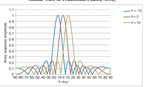
Figure 2. Formed beam with the resulted weights.
3.1. Test Complex Weights
In this step, three different angular positions of the UAV were supposed, and then the complex weights that resulted from the complex vector multiplication in Eq. (12) at each angular position were applied separately on a similar case of traditional phased array and see its formed beam for these complex weights. Figure 2 shows the formed beam in similar case of phased array for different UAV angular positions.
We can see that the formed beam is directed towards the angular position of the UAV, and the array response is equal to the peak of the array factor. So we can say that the proposed approach gives the array its required complex weights automatically at each angular position without using DOA and tracking algorithms, so reduces the computational cost of the tracking system.
3.2. Draw Array Response
The array response of the proposed tracking array as a function of the UAV angular position was drawn
by simulating the movement of the UAV within the angular position range [−90◦ + 90◦] and finding
the array response at each angular position. For non-isotropic array elements the element factor must be considered in the array response equation as in Eq. (25):
H(θ) =EF(θ)∗B(θ) (25)
where the element factor for dipole element is EF(θ) = cos(θ). Figure 3 shows the resulting array
response.
We can see that the beamwidth of the resulted array is [−45◦ +45◦] which is equal to the FOV.
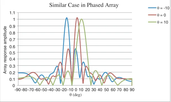
3.3. Eliminate Predefined Interference Signal
As we mentioned above, the possibility of receiving the interference signal will increase due to widening the beamwidth of the proposed array. The null steering ability was added to the resulted array using the “least square error pattern synthesis with nulls” method in order to cancel the predefined interference
signal. In this simulation, an interference source at angular position −5◦ was supposed. Then the
resulting complex weights at specific angular positions were applied to a traditional phased array, to verify that the proposed approach gives the desired complex weight for Equation (22) to synthesize the beam towards the UAV and NULL towards the interference source. Figure 4 shows the formed beam at different UAV angular positions.
-40 -35 -30 -25 -20 -15 -10 -5 0
-90 -80 -70 -60 -50 -40 -30 -20 -10 0 10 20 30 40 50 60 70 80 90
Array response magnitude(dB)
θ(deg)
Array Response
Figure 3. Array response.
θ = -10 θ = 0 θ = 10 Similar Case in Phased Array
-90 -80 -70 -60 -50 -40 -30 -20 -10 0 10 20 30 40 50 60 70 80 90 θ (deg)
0 0.1 0.2 0.3 0.4 0.5 0.6 0.7 0.8 0.9 1 1.1
Array response amplitude
Figure 4. Synthesized pattern with UNLL.
Then the array response of the proposed tracking array was drawn by simulating the movement of the UAV within the angular position range [−90◦ + 90◦] and the interference source at−5◦. Figure 5 shows the resulting array response after considering the element factor.
We can see that the array response has beamwidth equal to the FOV with null steering ability.
3.4. Evaluate Array Performance
The effect of the signal to noise ratio (SNR) and the phase error on the array performance was tested, where the beam pointing error (BPE) was taken as a metric to evaluate the improvement of the array performance by the proposed approach compared to the BPE of a tracking array that uses the monopulse tracking algorithm.
The beam pointing error here is the difference between the beam pointing angle and the angular position of the UAV, where the beam pointing angle is the angle at which the beam pattern has a maximum value and is given by:
B(θmax) = max
|B(θ)|2
(26)
and
-40 -35 -30 -25 -20 -15 -10 -5
0 5
-90 -80 -70 -60 -50 -40 -30 -20 -10 0 10 20 30 40 50 60 70 80 90
Array response magnitude(dB)
θ(deg)
Array Response with NULL
Figure 5. Array response with NULL.
where θmax for the proposed approach was found at each angular position by applying the resulted
complex weights on a traditional phased array as in Section 3.1.
In this part, we simulate the movement of the UAV within the FOV by changing the angular position within the range [−45◦ +45◦]. Figures 6, 7, and 8 show the beam pointing error of the proposed array and the monopulse tracking array at different SNR levels.
0 1 2 3 4 5 6 7 8 9 10
-45 -35 -25 -15 -5 5 15 25 35 45
BPE(deg)
Scan theta(deg)
Beam pointing error SNR =30 dB
proposed array
monopulse
Figure 6. BPE at SNR = 30 dB.
-2 0 2 4 6 8 10
-45 -35 -25 -15 -5 5 15 25 35 45
BPE(deg)
Scan theta(deg)
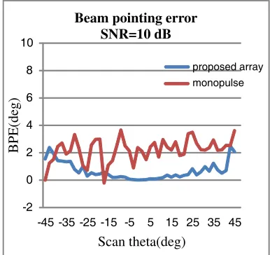
Beam pointing error SNR=10 dB
proposed array
monopulse
Figure 7. BPE at SNR = 10 dB.
We can see that the BPE for the proposed tracking array does not increase by the decrease of the SNR, while for the monopulse tracking array, the BPE increases by the decrease of the SNR.
Then the effect of the phase error on the array performance was tested, by considering the phase error in array response expression using Equation (14), where the phase error was assumed as a random variable with uniform distribution δn∼U[−σmax, σmax] where 0
◦
≤σmax≤180
◦
. Figures 9, 10, and 11 show the PBE of the array for different values of the phase error deviation.
0 1 2 3 4 5 6 7 8 9 10
-45 -35 -25 -15 -5 5 15 25 35 45
BPE(deg)
Scan theta(deg) Beam pointing error
SNR=5 dB
proposed array
monopulse
Figure 8. BPE at SNR = 5 dB.
0 1 2 3 4 5 6 7 8 9 10
-45 -35 -25 -15 -5 5 15 25 35 45
BPE(deg)
Scan theta(deg) Beam pointing error
Uniform σmax=5o
proposed array
monopulse
Figure 9. BPE atσmax= 5◦.
0 1 2 3 4 5 6 7 8 9 10
-45 -35 -25 -15 -5 5 15 25 35 45
BPE(deg)
Scan theta(deg) Beam pointing error
Uniform σmax=20o
proposed array monopulse
Figure 10. BPE at σmax= 20◦.
0 1 2 3 4 5 6 7 8 9 10
-45 -35 -25 -15 -5 5 15 25 35 45
BPE(deg)
Scan theta(deg) Beam pointing error
Uniform σmax=50o
proposed array
monopulse
4. CONCLUSION
In this paper, a proposed structure of tracking array to achieve auto tracking of UAV’s angular position is presented. The resulting array is a mixing of phased array and retrodirective array. Using the phase conjugation technique gives the ability to find the geometric phase of each channel by the complex vector multiplication canceling the need to use complex signal processing algorithms (DOA and tracking). A permanent high gain downlink is obtained due to the auto forming of the beam towards the UAV’s angular position. The phase errors of each channel will be included in its complex weights, so the effect of the phase errors will be reduced to the case of a single antenna system. Generating the phase conjugated version of the received signal on each channel separately gives the ability to apply it on a conformal array case.
REFERENCES
1. Okcu, H., “Operational requirements of unmanned aircraft systems data link and communication
systems,”Journal of Advances in Computer Networks, Vol. 4, No. 1, March 2016.
2. Dimc, F. and T. Magister, “Mini UAV communication link systems,” Conference: ICTS 2006,
International Conference on Traffic Science, December 2006.
3. Valavanis, K. P. and G. J. Vachtsevanos, Handbook of Unmanned Aerial Vehicles, Editors,
SpringerScience+BusinessMediaDordrecht, 2015.
4. Sharma, R. K. and B. B. Soni, “Analysis of a radar system for UAV tracking using MATLAB,”
International Journal of Engineering and Technical Research(IJETR), Vol. 7, No. 6, ISSN: 2321-0869 (O) 2454-4698 (P), June 2017.
5. Yeh, S. Y., “Development of a digital tracking array with single-channel RSNS and monopulse digital beamforming,” Naval Postgraduate School, Master’s Thesis, December 2010.
6. Dalbakk, L.-E., “Antenna system for tracking of unmanned aerial vehicle,” Norwegian University of Science and Technology, Master’s Thesis, June 2014.
7. Fulton, C., M. Yeary, D. Thompson, J. Lake, and A. Mitchell, “Digital phased arrays: Challenges
and opportunities,”Proceedings of the IEEE, Vol. 4, No. 1, March 2016.
8. Uchendu, I. and J. Kelly, “Survey of beam steering techniques available for millimeter wave
applications,” Progress In Electromagnetics Research B, Vol. 68, 35–54, 2016.
9. Foutz, J., A. Spanias, and M. K. Banavar,Narrowband Direction of Arrival Estimation for Antenna
Arrays, Morgan & Claypool Publishers, 2008.
10. Khmou, Y., S. Safi, and M. Frikel, “Comparative study between several direction of arrival
estimation methods,” Journal Of Telecommunications and Information Technology, 2014.
11. Van Trees, H. L., Optimum Array Processing. Part IV of Detection, Estimation, and Modulation
Theory, John Wiley & Sons, Inc, New York, 2002.
12. Mailloux, R. J., Phased Array Antenna Handbook, 2nd Edition, Artech House Antennas and
Propagation Library, 2005.
13. Gouri, N. N., N. Tiwari, and T. R. Rao, “An overview on beamforming and its issues for 60 GHz
wireless communications,” ITSI Transactions on Electrical and Electronics Engineering
(ITSI-TEEE), Vol. 1, No. 4, 2320–8945, ISSN (PRINT), 2013.
14. H¨ohne, T. and V. Ranki, “Phase noise in beamforming,” IEEE Transactions on Wireless
Communications, Vol. 9, No. 12, December 2010.
15. Sri Kavya, K. C., S. K. Kotamraju, B. N. Kumar, M. D. N. S. Mounika, S. Singh, and A. Sidda,
“Beam pointing accuracy of phased arrays for satellite communication,”Journal of Theoretical and
Applied Information Technology. Vol. 95. No. 10, May 2017.
16. Siu, M. C. L., “Effects of local oscillator errors on digital beamforming,” Naval Postgraduate School, Master’s Thesis, March 2016.
18. Golio, M., The RF and Microwave Handbook, CRC Press LLC, 2001.
19. Fakharzadeh, M., P. Mousavi, S. Safavi-Naeini, and S. H. Jamali, “The effects of imbalanced phase
shifters loss on phased array gain,”IEEE Antennas and Wireless Propagation Letters, Vol. 7, 2008.
20. Chen, L., Y. C. Guo, X. W. Shi, and T. L. Zhang, “Overview on the phase conjugation techniques of the retrodirective array,”International Journal of Antennas and Propagation, Article ID 564357, 2010.
21. Yang, C. and A.-X. Chen, “A direct conversion phase conjugation arithmetic for retrodirective
antenna array system,” 2011 4th IEEE International Symposium on Microwave, Antenna,
Propagation and EMC Technologies for Wireless Communications, November 1–3, 2011.
22. Miyamoto, R. Y., Y. Qian, and T. Itoh, “A reconfigurable active retrodirective/direct conversion
receiver array for wireless sensor systems,” IEEE Microwave Symposium Digest, 2001.
23. Leong, K. M. K. H., R. Y. Miyamoto, and T. Ito, “Ongoing retrodirective array research at UCLA,”
Technical Report of IEICE, SPS2002-08, 2003.
24. Goshi, D. S., K. M. K. H. Leong, and T. Itoh, “Recent advances in retrodirective system