Abstract—An induction or asynchronous motor is an AC electric motor in which the electric current in the rotor needed to produce torque is obtained by electromagnetic induction
from the magnetic field of the stator winding. Various studies have shown that anywhere from 70%, to as high as 90%, of faults on most overhead lines are transient. Three-phase induction (asynchronous) motors are industrial work-horses, responsible for consumption of 40–50% of generated electrical power. There are different kinds of induction motor faults, broadly classified as rotor and stator faults. The source of such faults could be external and/or internal due to various electrical, environmental, mechanical reasons. A transient fault, such as an insulator flashover, is a fault which is cleared by the immediate tripping of one or more circuit breakers to isolate the fault, and which does not recur when the line is re-energized. Faults tend to be less transient (near the 80% range) at lower, distribution voltages and more transient (near the 90% range) at higher, sub transmission and transmission voltages. In the present paper, automatic fault detective analysis for protection of three phase induction motor has been investigated and experimental set up have been carried out for the required detective analysis by using PIC18F452 microcontroller and has also been shown in C Programming. The normal and abnormal conditions of voltage and current parameters for 3ϕ, 415V, ⁄ HP induction motor have been discussed based upon the performance of present investigation. It has been found that under short circuit and under/over voltage conditions, the current/voltage through the respective phases are differ from the normal operating conditions.
Keywords:Induction Motor, Permanent and Temporary Faults, PIC Microcontroller, Overvoltage, Short Circuit.
I. INTRODUCTION
In an electric power system, a fault is any abnormal flow of electric current. For example, a short circuit is a fault in which current flow by passes the normal load. In three phase systems, a fault may involve one or more phases and ground, or may occur only between phases. In a “ground fault” or “earth fault”, current flows into the earth.
The prospective short circuit current of a fault can be calculated for powersystems. In power systems, protective devices detect fault conditions and operate circuit breakers and other devices to limit the loss of service due to a failure. An induction or asynchronous motor is an AC electric motorin which the electric current in the rotor needed to produce torque is obtained by electromagnetic induction from the magnetic field of the stator winding. An induction motor therefore does not require mechanical commutation, separate-excitation or self-excitation for all or part of the energy transferred from stator to rotor, as in universal, DC and large synchronous motors. An induction motor's rotor can be either wound type or squirrel-cage type. Three phase squirrel-cage induction motors are widely used in industrial drives because they are rugged, reliable and economical. Single-phase induction motors are used extensively for smaller loads, such as household appliances like fans. VFDs offer especially important energy savings opportunities for existing and prospective induction motors in variable-torque centrifugal fan, pump and compressor load applications. Squirrel cage induction motors are very widely used in both fixed-speed and VFD applications. Three-phase induction (asynchronous) motors are industrial work-horses, responsible for consumption of 40–50% of generated electrical power. Therefore, the diagnostics of induction motor problems are of prime importance. There are different kinds of induction motor faults, broadly classified as rotor and stator faults. The source of such faults could be external and/or internal due to various electrical, environmental,mechanical reasons. In this paper, we have designed system where the faults are detected and after clearing those faults motor get auto turn on which depends on temporary or permanent faults. There is one PIC microcontroller is used to detect the faults like short circuit and over/under voltage and turn off motor. Relays are used to operate supply to switch off load in case of short circuit.
Automatic Fault Detection And Protecton In
Three Phase Induction Motor
Mr. Anil Tekale Mr. Amardeep Potdar
M-Tech Scholar
M-Tech Scholar TGPCET Mohgaon, Nagpur
TGPCET Mohgaon, Nagpur
[email protected]
[email protected]
Prof. Swapna God Dr. Harikumar Naidu
Assistant Professor Head, Electrical Engineering Department
Parikrama Group of Institutions, Kashti TGPCET Mohgaon, Nagpur
II. SYSTEMOVERVIEW 1. FAULT DETECTION CIRCUITORY
The block diagram of fault detection circuit contains various blocks like PIC18F452, R phase voltage sensor, R phase current sensor, LCD etc. as shown in Figure 1. The load current will be measured by the current transformer which is given to the current sensing circuit which will convert the 1A ac current to 5V dc and given to the AN0, AN1 and AN3 channels of ADC of PIC18F452. All the processed values are compared with predetermined standard limits. If the measured value will not be within the limit then it will disconnect the Induction motor.
Figure1. Fault Detection
This is used to control the loads according to the priority of thecustomer’s uses within their time limit. The same three current sensorsoutputs are given to the ADC of PIC18F452 controller which will sense theload current and it is given to the ADC of the PIC18F452 as shown in Figure1.When the motor is in running condition then there is normal current through the circuit. After the short circuit fault this current becomes higher than normal current. At that time CT sense, the increased current and givesanalog output via current sensing circuit. After that ADC of the PIC18F452works and convert this analog output into the digital output and when there is changes in digital value then each relay gets NO, either any value at ADC is change then again relay get NC and motor get started automatically with graduallyincreasing voltage level, it can be happening if and only if there is temporaryfault occurred which having time duration of 0 to 5 seconds. If fault couldnot be cleared within the time limit then this fault is defined as permanentfault and for permanent fault motor gets disconnected for long time.
2. CONTROL POWER SUPPLY CIRCUIT:
A three phase rectifier used to convert ac supply to the dc in two different voltage levels of 5V and 12V as shown in Figure 2. A three phase star-delta transformer is used to convert 415V/12V. Capacitor filter is used to remove the ripples from the rectified output of the rectifier. MOVs are used to protect transformer winding from overvoltage. The fixed voltage regulators 7805 and 7812 are used to convert the rectifier output of the rectifier to fixed 5Vdc and 12 Vdc.
Figure2:Control Power Supply of 5V & 12V
3. CURRENT SNSOR
By using this circuit, we can convert the load current into the 0-5Vdc as shown in Figure 3. To step down the current we can use the current transformer which secondary current is 1A. CT secondary is connected to the bridge rectifier across which a 5Ω resistor is connected. When 1A current flows through the circuit a 5V drop will be across the 5Ω resistor. A capacitor is used as a filter. The required voltage is adjusted across the resistor R2 by setting the preset RP.
Figure3: Current Sensing
III COMPUTER PROGRAMME
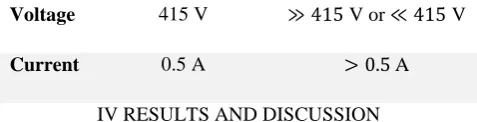
To ensure the validity and accuracy of the calculations, the results are availed from experimental data. Normal operation and abnormal operation of three phase induction motor is compared. The specifications of the model under normal and abnormal conditions are shown in Table 1. (See. Appendix A& B)
Table 1. Test model Specifications and conditions
Normal Condition Abnormal Condition
Voltage 415 V V or V
Current 0.5 A A
IV RESULTS AND DISCUSSION
The results for detection and protection of three phase induction motor under normal and abnormal conditions are obtained as shown in Table 1. For normal working condition
voltage across the motor is 415V which is required to run motor and during this period current flowing through each phase is 0.5A. Under abnormal condition (when short circuit or overvoltage faults takes place), the voltage across three phase is not equal to 415V that means unbalance in voltage takes place or during short circuit, current flowing through circuit is asymmetric in each phase then motor gets disconnect automatically vice versa. These all operations and resultsare analyzed in this paper and designed system is shown in Figure 4.
Figure2:Designed System
V CONCLUSIONS
A system has been designed for the detection and protection of induction motor under abnormal conditions. Some concluding observations from the designing are given below.
Under short circuit conditions, current flowing through each phase is different and more than normal current rating.
During the under voltage or overvoltage faults voltage across motor get vary.
As per new designed protection technique motor get disconnect during faulty condition and after clearing these faults motor get starts automatically without any damage.
REFERENCES
1. Muhammad Ali Mazidi, Rolin D. McKinlay, Danny Causey
“PIC Microcontroller and Embedded system using Assembly
and C for PIC18”.
2. Anil Tekale, Dinesh Nawani, NilamBelkar and Vishal Devkar, a Review Paper on Power Quality Issues and Mitigation Strategies. Journal for Advanced Research in Applied Sciences. Volume 4, Issue 4, Sept-2017; Pages: 51-57
3. Microchip “Datasheet of PIC18F452”.
4. Zoolnasri Bin Abu Harun, University Malaysia Pahang, “Over Current Protection Relay Using PIC Micro Controller”,
Project report. PP 1-24
5. “Microcontroller based fault detection”, International Journal
of Advancements in Research & Technology, Volume 1, Issue 5, October-2012 1 ISSN 2278-7763
6. https://www.researchgate.net/publication/321097011_Automat ic_Fault_Detection_And_Protection_Of_Three_Phase_Inducti on_Motor
7. “Three Phase Fault Analysis with Auto Reset for Temporary
Fault and Trip for Permanent Fault”, Sathish Bakanagari1, A.
Mahesh Kumar2, M. Cheenya3, 12(Asst.prof in EEE Department) 3(Asst.Prof in ECE Department) Mahaveer Institute of Science and Technology, bandlaguda, Hyderabad.A.P.
8. “Fault detection and protection of induction motors using
sensors”, 2008, RamazanBayindir, Ibrahim Sefa, İlhamiColak,
and AskinBektas
9. M. E. H. Benbouzid, “Bibliography on induction motors faults detection and diagnosis,” IEEE Trans. Energy Convers., vol. 14, no. 4, pp. 1065-1074, Dec. 1999.
10. “INDUCTION MOTORS - PROTECTION and STARTING by
VIV COHEN “Circuit Breaker Industries, P.O. Box 881,
Johannesburg 2000, South Africa.
11. Vaibhav Ware, Ganesh Dungahu, TukaramArade, Anil Tekale, Swapna God "AMORPHOUS TRANSFORMER: STUDY PAPER" International Journal for Science and Advance
Research in Technology, 3(10)
12. Anil Tekale, MadhuriJadhav, ShitalBhalke, PratibhaBhudhe “AUTO PHASE SELECTION BASED ON POWER FACTOR MEASUREMENT “International Research Journal of Engineering and Technology (IRJET) Volume: 04 Issue: 05 | May -2017, 3144-3147.
APPENDIX A
1. REPRESENTATION AND FIGURES OF
DESIGN CHARTS
In the present work a number of design charts are used for the calculation of digital values from the obtained analog values. These figures are adapted from the design charts given by Muhammad ali mazidi. [1].
Table 2.Analog to Digital Conversion
A simple linear calculation is used to find the value for conversion used in the design as follows:
Voltage level
[mV]
Hex Number
Decimal
Number
0.00-0.48
000
0
0.48-0.96
001
1
0.96-1.44
002
2
1.44-1.92
003
3
.
.
.
.
.
.
APPENDIX B
2. COMPUTER PROGRAMME
B.1. INTRODUCTION
A computer code, for the execution of designed system developed in the present work. This programme is based on the analytical and digital methods. The computer
programme can serve two main purposes: firstly, in the design stage, a rapid study of design can be performed to allow the optimum configuration compatible with the requirements to be found and secondly, by calculating the voltages and currents which were changed as per different conditions.
The programming for designed system has been elaborated as follows:
#include<P18F452.h>
# define RC0 PORTCbits.RC0 # define RC1 PORTCbits.RC1 # define RC2 PORTCbits.RC2 # define RD0 PORTDbits.RD0 # define RD1 PORTDbits.RD1 # define RD2 PORTDbits.RD2 void ADC1(void);
void delay (unsigned int value); unsignedint A, B;
unsignedinti,j;
////ADC for conversion/////////////////////////////////////////////// void main ()
{
UnsignedintVrl,Vrh,VR,Vyl,Vyh,VY,Vbl,Vbh,VB; TRISC=0X00;
TRISD=0X00;
while (1) ///continuous scanning loop////////// {
/////// AN0 /////////
ADCON0=0x81 ///A/D convertor module is powered up & RA0 as i/panalog
ADC1 (); ///A/D loop is called////////// Vrl=A;
Vrh=B; Vrh=Vrh<<8; VR=(Vrh|Vrl); delay (10); /////// AN1 /////////
ADCON0= 0x89 ///A/D convertor module is powered up & RA1 as i/panalog
ADC1 (); Vyl=A; Vyh=B; Vyh=Vyh<<8; VY= (Vyh|Vyl); delay (10); /////// AN2 /////////
ADCON0= 0x91 ///A/D convertor module is powered up & RA2 as
i/panalog pin// ADC1 ();
Vbl=A; Vbh=B; Vbh=Vbh<<8; VB= (Vbh|Vbl); delay (10);
/////////// End of Channels Scan /////////////// if ((VR>0000) |(VY>0000) |(VB>0000)) {
RC0=1; RC1=1; RC2=1; RD0=1; RD1=1; RD2=1; }
//else if(VY>0001) ///// {
// RC0=1; // RC1=1; // RC2=1; // RD0=1; // RD1=1; // RD2=1; // }
//else if(VB>0001) ////// {
RD1=0; RD2=0; } } }
void ADC1(void) {
ADCON1=0x80 ////Right justified. ////// ADCON0bits.GO=1 ////A/D conversion in progress////////////
while (ADCON0bits.GO==1);
A=ADRESL ////store lower value of ADC in A.//////////
B=ADRESH ////store higher value of ADC in B.////////////
}
void delay (unsigned int value) {
Unsignedinti, j; for (i=0; i<value;i++) for (j=0; j<62; j++); }
B.3. PROGRAMME STRUCTURE AND DESCRIPTION OF SUBROUTINES