IJEDR1603142
International Journal of Engineering Development and Research (www.ijedr.org)881
Design, Development and Analysis of Femur Bone by
using Rapid Prototyping
N.D. Deokar1, Dr. A. G. Thakur2
1PG Research fellow, SRES’s College of Engineering, Kopargaon
2Asso. Professor & PG Teacher SRES’s College of Engineering, Kopargaon, Maharashtra, India
________________________________________________________________________________________________________
Abstract—Most of the bone fractures in daily life occur within the arm bone and femur bones. Machining of medical science alloy implants, with high speed machining, offers blessings, however additionally has its own disadvantages metallic element, steel etc. are used as bone replacement; however the implants are unit straightforward geometric approximations of the bone. There is lot of probabilities of mismatches to occur between real bone and implants, which regularly causes stress concentrations and premature implant failure. To beat this stress concentration and unsustainable pain correct bone implant is needed. By Appling Rapid prototyping we are able to prepare the image to induce physical model of bone. This can be helpful to manufacture correct bone implant. This paper tries to utilize the advanced Computer Aided Design and Finite component Analysis to notice and perceive the stress within the femur bone, and aid within the manufacture of artificial joints and limbs. This method takes input from CT scan or MRI, That is then fed into CAD by using different software’s like MIMIC and 3D slicer. This CAD file can be used in prototyping the bone by using different methods of Rapid Prototyping. And it will help in different medical application.
Index Terms—Computer Aided Design; CT scan; Femur Bone; Rapid Prototyping.
________________________________________________________________________________________________________
I. INTRODUCTION
Rapid prototyping methods are unique in that they add and bond materials in layers to form objects. Such systems are also known by the general name free form fabrication, solid freeform fabrication and layered manufacturing. Nowadays, more than 30 different processes with high accuracy and a large choice of materials exist. These processes are classified in different ways on the basis of materials used, by energy used, by lighting of photopolymers, or by typical application range. Rapid prototyping is one among the quickest developing producing technologies within the world these days. RP have tremendous advantages in medical field. Firstly Rapid Prototyping is fastest developing technology in all fields of engineering and medical both. It is using for preparation of prototype before mass production for testing and changing purpose. Rapid Prototyping is the costly process but overall cost is low. RP give physical model for observation and testing purpose, failure of material after come in market is reduced.[1] RP is also useful for modification of product in less time and see the physical model for farther changes if required. Due to all advantages in all field research is doing by different companies and research center to improve present research and reduce cost of production. There are some limitations for using materials for prototype preparation. Because, it is difficult to manufacture prototype by using all metals, second is not possible to manufacture prototype of large size. Also it is time consuming. [2]
Accidents are the major cause of bone fracture. In day to day life car accidents or any other Mischance are occur due to increase in population on road. In this accident bone fracture is frequently happen. For medical treatment and for surgical planning doctors are using CT scan image or MRI image. CT scan give 3D visualization of bone but it can give physical model type feel. Preparing prototype has same advantages in surgical planning and implant fixation. [3]
Rapid prototyping technology was originally developed to quickly build an image of a brand new product, particularly in industry. Currently constant technology is employed within the medical field within the production of anatomical models and templates, that facilitate surgeons to optimize operative surgical designing, interactive surgical simulation, whereas reducing operative time and complications. [4]
II. LITERATURE REVIEW
Ludmila Novakova et al. discussed about rapid prototyping technologies the initial state of material can come in either solid, liquid or powder state. The current range materials include paper, metals and ceramics. In fused deposition modeling are used as basic material ABS - Acrylonitrile Butadiene Styrene, polyamide, polycarbonate, polyethylene. In its place of these materials in special FDM applications can be used silicon nitrate, PZT, aluminium oxide, hydroxypatite and stainless steel for a variety of structural, electroceramic and bioceramic applications.
Odokuma Emmanuel Igho et al. Study was aimed to determining the pattern of bone fractures in City. Two hundred and sixteen bone fracture cases were reviewed, and the fractures were observed to have occurred more in males than in female. Majority of the fractures were observed in the femur, and least in the patella. Road traffic accidents were observed to be the leading cause of bone fractures.
IJEDR1603142
International Journal of Engineering Development and Research (www.ijedr.org)882
III. PROBLEM IDENTIFICATION IN BONE SURGERY
After consulting with Doctors most of the bone fracture in day-today life happens within the arm bone and femur bones. [5] Mismatches will occur between real bone and implants typically inflicting stress concentrations and premature implant failure. Additional conventional machining of metallic element implants, with 5-Axis High Speed Machining, that offers benefits, however conjointly has disadvantages like, Machining of metallic element or steel will be done economically on a routine production basis, if shop procedures are set up to allow for the physical characteristics common to the metal [6]. CT scan giving the illusion of 3D volumes on a 2nd screen will cause issues through angle, depth, transparency and lighting anomalies that manifest as viewing orientation uncertainties. Accuracy of implant is another issue.
Use of physical models for treatment designing and visualization rather than using X-ray, CT scan or MRI images as input increase accuracy in bone manufacturing and reduce the errors. As the errors are reduced and we get the exact shape of bone, patient does not fill any pain in their bone [7].
The paper contain process of preparing prototype of femur bone and also do the stress analysis by using CT scan as input data. About femur bone, Femur is the longest bone in the human body and the only bone present in thigh. And also the strongest bone in the human body. Its length on average is 26.74% of a person's height. Femur fractures can happen when a great force is put on the side of the upper leg or when the foot is pushed on, extending the force upward to the femur. This kind of force happens with a fall from a great height or an automobile injury. Fractures of the femur can happen near the ball at the top of the joint and are called “hip fractures”. A true femur fracture happens in the shaft of the femur [8]. Such fractures operate under the force of a great deal of muscle strength so they almost always displace and shorten.
IV. FUSED DEPOSITION MODELING (FDM)
Fused deposition modeling is the second most commonly used process after Stereo lithography Plastic filament supply coil is the filler coil which continuously supply filament to nozzle. ABS material is used as filament for common purpose. Extrusion nozzle is having motion in all three directions. At one end filament supply coil is attached and in opposite end heater is attached. Heater heat the filament up to semi molten state. At the tip of nozzle hopper is there for filtering extrusion. Some lower-cost configurations of the machinery use plastic pellets fed from a hopper rather than a filament. Table is used for supporting the object which is to be manufacturing [9].
Input to the FDM machine is given in the .stl file format because only STL file is readable to FDM machine. After giving input to the FDM machine start their working. Filament drum continuously start supplying filament to nozzle. After coming filament in nozzle it heated up to semi molten state to pass through nozzle. Nozzle start moving in programmed manner and filament is continuously coming out from nozzle and for a layer on top of another. [9] Femur bone is prepared after number of slices one over another prepares in programmed manner. If suppers are required to any part due to cantilever shape then supporting structure is prepare. After completing the object supporting structure is cut. Figure 1 shows simple fused deposition modeling process.
Fig. 1.FDM Process representation diagram [10]
V. MATERIALS
Materials used in rapid prototyping are both metal and nonmetal. Non-metals thermoplastics like ABS, PC, and PPSF are commonly used. Thermoplastics having properties like elasticity, strong, toughness. And in metals steel, different alloy steel, aluminum used as filaments.
A. Acrylonitrile Butadiene Styrene (ABS)
IJEDR1603142
International Journal of Engineering Development and Research (www.ijedr.org)883
VI. THE FUNDAMENTAL METHOD
A. CAD Model Creation:
Fig. 2.CT scan unit
3D digital image will be obtained by CT scanner or MRI information. These imaging technologies are used for modeling internal structures of human’s body. Medical models made up of this information should be terribly correct and since of this they need a spiral scanning technique that permits to try to full volume scanning. This makes potential to get a high variety of slices. The constituent dimension in every slice may well be reduced computation on every case. Most CT and MRI units have the power of commerce information in common medical file format. Figure 2 shows process of taking computer topographic image machine and figure 3 shows three dimensional view of CT scan. (DICOM – digital imaging and communication in medication)
Fig. 3.3D view of CT scanned bone
B. Translate the CAD model to STL format
IJEDR1603142
International Journal of Engineering Development and Research (www.ijedr.org)884
Fig. 4.Bone in MIMIC softwareC. Slice the STL file into number of layers
In the third step, a pre-processing program prepares the STL file to be designed. Many programs are a unit obtainable, and most enable the user to regulate the dimensions, location and orientation of the model. Build orientation is vital for many reasons. First, properties of fast prototypes vary from one coordinate direction to a different. As an example, prototypes are a unit typically weaker and fewer correct within the z (vertical) direction than within the x-y plane. Additionally, half orientation partly determines the quantity of your time needed to make the model. Putting the shortest dimension within the z direction reduces the quantity of layers, thereby shortening build time. The pre-processing computer code slices the STL model into range of layers from 0.01 mm to 0.7 mm thick, betting on the build technique as shown in figure 6. The program can also generate associate supporting structure to support the model throughout the build. Supports are an element helpful for delicate options like overhangs, internal cavities, and thin-walled sections. Every RP machine manufacturer provides their properties preprocessing computer code. Figure 5 shows noise reduction by using catia and model preparation for prototyping.
Fig. 5.Femur Model Preparation
D. Construct the model one layer over another
IJEDR1603142
International Journal of Engineering Development and Research (www.ijedr.org)885
Fig. 6.Preparation of STL File for PrototypingE.Clean and Finish:
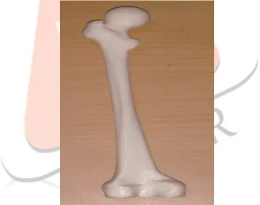
The final step is post-processing. As it is layer by layer manufacturing accuracy is depends on thickness of slice. This involves removing the prototype from the machine and cracking any supports if available. Some light-sensitive materials have to be compelled to be absolutely cured before use. Prototypes can also need minor improvement and surface treatment. Sanding, sealing, and/or painting the model can improve its look and sturdiness [12]. Figure 7 shows final prototype model after cleaning and finishing.
Fig. 7.Human femur bone by RP
VII. APPLICATIONS
A. Great improvements to the fields of prosthetics and implantation.
RP techniques are helpful in creating prostheses and implants for years. The power to quickly work corrective to a patient's distinctive proportions may be a nice advantage. The techniques also are used for creating hip sockets, knee joints and spinal implants for quite your time. The created model may be used as a master model of the customer implant. Several researchers explored new applications of RP during this field.
B. Designing and explaining complicated surgical operations
This is vital role of RP technologies in medication that modify pre surgery designing. the utilization of 3D medical models helps the doctor to set up and perform complicated surgical procedures and simulations and offers him a chance to review the bone structures of the patient before the surgery, to extend surgical exactitude, to cut back time of procedures and risk throughout surgery also as prices . 3D physical model will be very helpful for surgery designing and higher understanding of the matter also as for teaching purpose. Surgical designing is most frequently finished stereo lithography wherever they created model has high accuracy, transparency however restricted variety of colors and 3DP (for a lot of colored models, presentation of FEA results).
IJEDR1603142
International Journal of Engineering Development and Research (www.ijedr.org)886
RP models will be used as teaching aids for college kids within the college room also as for researchers. These models will be created in several colors and supply a far better illustration of anatomy, permit viewing of internal structures and far higher understanding of some issues or procedures that must to be taken in existing case. They’re conjointly used as teaching simulators.D. Design and manufacturing bioactive implants and tissue engineering.
RP technologies gave vital contribution within the field of tissue engineering through the utilization of biomaterials as well as the direct manufacture of bioactive implants. Tissue engineering may be a combination of living cells and a support structure referred to as scaffolds. RP systems like fused deposition modeling, 3D printing and selective laser sintering are tried to be convenient for creating porous structures to be used in tissue engineering. During this field it's essential to be able to fabricate three-dimensional scaffolds of assorted geometric shapes, so as to repair defects caused by accidents, surgery, or birth.
E. Arts and Archeology
Selective Laser Sintering with marble powders can be used to restore or duplicate ancient statues and ornaments, which undergo from environmental influences. The originals are scanned to derive the 3D data, damages can be corrected by using the software and the replica can be created easily. One application is duplicating a statue. The original statue was digitized and a smaller model was produced to serve a base for a bronze casting process.
VIII. CONCLUSION
Use of physical models for patients treatment planning and visualization instead of exclusively using RP models based on X-ray computer tomography or magnetic resonance imaging data has a number of distinct advantages. In accordance with solid model obtained after CT/MRI. It is possible to manufacture femur bone implants from block material on milling machine. Approach in bone surgery treatment that was presented in this paper offers great potentials in time saving and eventually possible postoperative treatments. This procedure is revolutionized since it could be planed and starts at the moment when the preventive CT/MRI is performed. All the phases are based only on CT/MRI data and procedure of implant production is automatically linked with CT/MRI report. That means that the human errors and its leakage are minimize to least and the operation results because of that become more successful. Machining time has to be improved and we pointed out a tool selection as very important and critical in that manner. Also, there is consideration regarding tool path overlapping to achieve better surface quality.
However this is just a small step ahead. There are many unanswered medical problems and many beliefs from Rapid Prototyping in this areas. Development in speed, cost, accuracy, materials and tight collaboration between radiologists, surgeons and engineers is required and so are constant improvements from RP vendors. This will help Rapid Prototyping technologies to give their maximum in such an important field like medication.
REFERENCES
[1]. Wei-chen Lee, Ching-chih Wei, Shan-Chen Chung. Development of a hybrid rapid prototyping system using low-cost fused deposition modeling and five-axis machining, Journal of Materials Processing Technology 214,ScienceDirect, 2014. P.2366–2374.
[2]. L. Villalpandoa, H. Eiliata, R. J. Urbanicb, An optimization approach for components built by fused deposition modeling with parametric internal structures,ScienceDirect, 2014, Pp. 800 – 805.
[3]. P.M. Pandey, N. Venkata Reddy, S.G. Dhande, Part deposition orientation studies in layered manufacturing, P.M. Pandey et al. / Journal of Materials Processing Technology, 2006. Pp. 1-7.
[4]. LudmilaNovakovaMarcincinova, Ivan Kuric, Basic and Advanced Materials for Fused Deposition Modeling Rapid Prototyping Technology, 2012, Pp. 24-27.
[5]. Odokuma Emmanuel Igho, OgwaraAkpogheneIsaac, OsemekeOnyemaechiEronimeh, Road Traffic Accidents and Bone Fractures in Ughelli, Nigeria, IOSR Journal of Dental and Medical Sciences, Volume 14, Apr. 2015, Pp. 21-25.
[6]. S. Kumar, J.-P. Kruth, Composites by rapid prototyping technology, Materials and Design 31, Pp. 850–856.
[7]. Xishi Wang , Tian Ying Wang , Fuchuan Jiang ,YixiangDuan , “ The hip stress level analysis for human routine activities” , Biomedical Engineering Applications, Basis & Communications , 17, 2005, pp.153-158.
[8]. D. Bubesh Kumar, Dr. K.G.Muthurajan, Finite Element Analysis of Equivalent Stress and Deformation of Cement less Hip Prosthesis, A Review on Energy Saving Using Green Computing System| ISSN: 2321-9939,pp. 93-97.
[9]. R. VenkataRao, Dhiraj P. Rai, Optimization of fused deposition modeling process using teaching learning based optimization algorithm, Engineering Science and Technology an International Journal, 2015, Pp. 1-16.
[10]. D. Chandramohan, K. Marimuthu, Rapid Prototyping/Rapid Tooling - A Over View And Its Applications In Orthopaedics, International Journal Of Advanced Engineering Technology, Vol.2,Issue Iv, Oct-Dec 2011, Pp. 435-448. [11]. Sofia P. Faria, Paulo R. Fernandes, Joao O. Folgado,Modeling Approaches On The Lumbar Spine Biomechanics - A
Comparative Study, VI International Conference on Computational Bioengineering ICCB 2015 S. Faria, P. Fernandes and J. Folgado, Pp. 1-12.
![Fig. 1.FDM Process representation diagram [10]](https://thumb-us.123doks.com/thumbv2/123dok_us/8268186.1375880/2.595.165.437.422.609/fig-fdm-process-representation-diagram.webp)