29-397r01_Power_Supply_Sep74.pdf
51
0
0
Full text
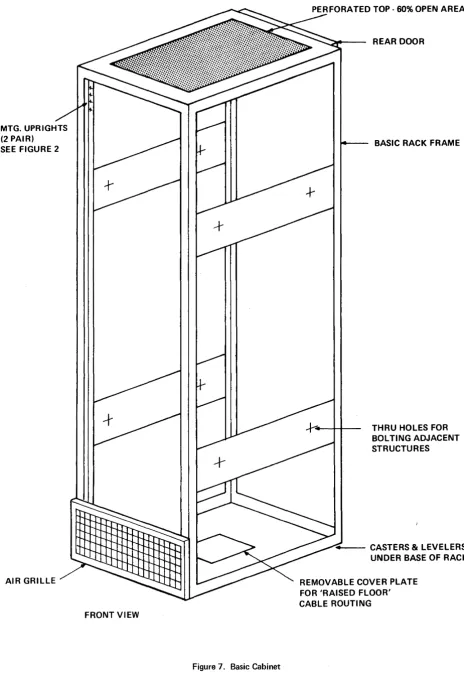
Figure
+7

Related documents
In the menu operation, the icon in red or cursor is the currently selected menu; the icon in blue is the unselected menu; press ENTER to confirm; press the encoder to cancel
When measuring constant current performance specifications, the power supply's voltage control must be set above the maximum output voltage that the supply will deliver, since
Apply power to transformer. L4 should light.. Check capacitors to see if shorted or open. Check and replace bad ones. Check for proper polarity and solder
Figure 8 – RD650 Rear View - Riser Card Expansion Slots and AnyFabric Slot The following server configurations support PCIe riser card expansion:.. A server configuration
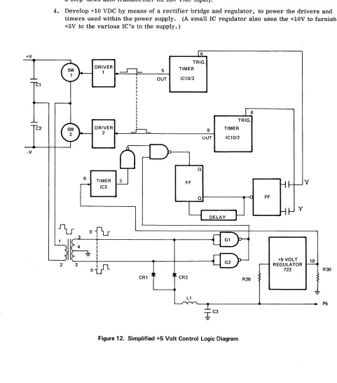
The second half of the power cycle is described in the Output Circuit description.. CR2 is forward biased, and regenerative
Then, when you solder the connection, make sure the solder remains in this area and does not bridge to-another foil.. This is especially important when the foils are
- Output socket/Output plugs: USB socket type A micro and mini USB plugs by using supplied adapter lead.. For cameras,
Operating in series mode doubles voltage on variable channels to 0 ~ 60V, while parallel mode offers 0 ~ 6 Amp current rating. MODEL GPS 4303 – FOUR independent, voltage
