BUCKLING PROPOGATION IN CORRODED PIPE
LINES CONSIDERING THICKNESS AS A RANDOM
VARIABLE
Bantupalli Sravan Teja
Dept. of Civil, Pydah College of Engg. Visakhapatnam, (India)
ABSTRACT
Propagation pressure for offshore intact and corroded pipelines is calculated by Rigid Plastic Analysis based
on average thickness and using thickness variation. For generating thickness it is assumed that the thickness
follows uniform distribution. Further the same work is carried out using normal distribution and is found that
the results can be used for any random thickness variation. Fourier Approximation is made to the thickness
generated using uniform distribution to resemble practical situation. Application of using thickness variation is
checked for corroded pipe and is found that it is applicable to small angular extent of corrosion with small
relative depth of corrosion and large angular extent of corrosion for any relative depth of corrosion.
I. INTRODUCTION
Fig .2 Buckling of an offshore pipeline during laying process (Kyriakides.S, Corona.E, 2007)
Fig 1 Collapse of an offshore pipeline (Kyriakides.S, Corona.E, 2007)
render projects far too costly. This failure mode is therefore controlled by inserting buckle arrestors. These thicker sections of pipe limit the buckle‟s travel by preventing it from crossing over.
Fig .3 Schematic diagram of Propagating buckle (Michelle S. Hoo Fatt, 2001)
Fig 4 Buckling propagation in a pipeline due to impact by an anchor (Kyriakides.S, Corona.E,
2007)
II. PROBLEM DESCRIPTION
dimensional. Corrosion is also considered as uniform along the length of the pipeline. Detailed description of corroded pipe is given in section .
III. INTACT PIPE
As explained earlier in seamless pipe inside surface is generally smooth as surface of the piercer cylinder used to pierce through billet is smooth. But the outside surface is irregular due to uneven heating and rolling. This results in thickness variation in cross section and along the length. To simplify the problem same thickness variation is assumed at all cross sections. Solutions obtained from such assumption will yield conservative estimates of failure load. The pipeline is assumed to be in a state of plane strain. Cross-sections in the pipeline perpendicular to the longitudinal axis of the pipeline remain plane. The pipeline is considered to be composed of ring elements. Stresses in a ring element of the pipeline do not interfere with the deformation of the adjacent ring elements. Therefore, one can analyze the deformation of the ring element to approximate the collapse of the pipeline.
IV. CORRODED PIPE
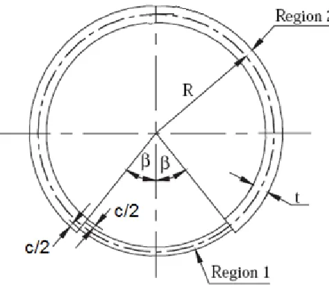
The corroded pipeline is modeled as a non-uniform, infinitely long cylindrical shell with a cross-section as shown in Fig 2.1. The non-uniform shell is divided into two regions. Region 1 has a thickness of „t– c’ and is subtended by an angle of 2β where t is the average thickness of the shell, c is the thickness reduction and β is the angular extension of the non-uniformity. Region 2 has a thickness of t with angular extension of 2(π-β). The thickness is symmetric about the circumferential neutral surface of the shell in both Regions 1 and 2.
Fig. 5 Cross section of corroded pipe
Rigid plastic analysis is used to find the propagation pressure in both intact and corroded pipes. In the analysis, the material of the corroded pipeline is idealized as perfect, rigid plastic. Four plastic hinges are used to approximate the collapse mechanism of the corroded pipeline. Plastic work dissipated in the pipeline is calculated from a ring collapse mechanism due to circumferential bending at the four plastic hinges. For the intact pipe the mode of buckling is anti-symmetric. In corroded pipe both symmetric and anti-symmetric modes are possible. For both symmetric and anti-symmetric modes, the principle of virtual work and upper bound theory are used to find the buckle propagation pressure.
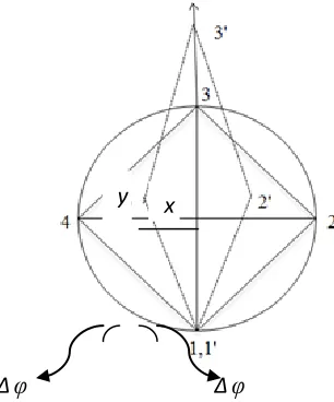
When small angular deformation Δ is given as shown in fig 6, the change in angle between the lines joining the plastic hinges at each hinge can be found using the geometry of the figure. According to energy theorem, external virtual work is equal to plastic energy dissipated in pipe.
Fig. 6 Deformed shape of intact pipe
2
π
So,
angles.
right
at
are
hinges
joining
lines
the
Initially
.
hinge
at
hinges
plastic
joining
lines
between
angle
final
is
'
,
hinge
at
hinges
plastic
joining
lines
between
angle
initial
is
,
hinge
at
hinges
plastic
joining
lines
between
angle
in
change
is
,
hinge
at
moment
plastic
is
,
hinges
plastic
joining
lines
by
enclosed
area
in
change
is
pressure,
external
is
where
3.1
A
form
al
mathematic
In
4 3 2
1
θ
θ
θ
θ
i
i
i
Δθ
i
M
ΔA
P
i
Δθ
i
M
PΔ
i i i i
Δ
φ
Δ
φ
Δφ
Δθ
Δφ
θ
θ
'
2
2
Fig.3.2
the
of
geometry
the
From
1 11
-
1
1
1
-1
8
)
(1
8
0
n
n
Δθ
y
σ
En
n
Δθ
y
y
σ
σ
Here, at all the hinge points, Δθ=2Δ is the same, thereby making σ0 same at all the hinges. Hence their
corresponding moments are also the same.
Normalized propagation pressure :
Normalized propagation pressure is defined as ratio of propagation pressure of corroded pipe to that of the intact pipe. It is denoted by the symbol ɳ.
where is the propagation pressure of corroded pipe. is the propagation pressure of intact pipe
.
V. RESULTS USING THICKNESS VARIATION
Initially thickness is generated assuming that it follows uniform distribution between allowable tolerances. In this formulation the constant (average) radius is used. But in reality radius also changes, to demonstrate this, in next formulation radius is also considered as variable. The same procedure is repeated again by assuming the variables (thickness and radius) follow normal distribution. Then finally a Fourier approximation is made to the thickness developed using uniform distribution to represent the thickness as a function of θ (circumferential position). Then by using this t(θ) propagation pressure is calculated. Detailed explanation about these procedures, their application to the problem previously considered and comparison is given in subsequent sections of this chapter. As mentioned in Table 1.1, DNV code allows ±12.5% variation from average thickness for t ≥10 mm. In the present case as t =18.29 mm, thickness can vary from 16.004 mm to 20.576 mm. Assuming that thickness follows uniform distribution between these limits, t is generated. A brief description of the procedure is given below.
Cumulative distribution function of the uniform distribution is
dt
a
b
C
t
a
1
Where a and b are upper and lower limits of the distribution respectively and C is cumulative distribution function which varies from 0 to 1. In the present case
a = 16.004 mm
b = 20.576 mm
On integrating Eqn(5.1) and rearranging the terms
t = C(b-a) + a
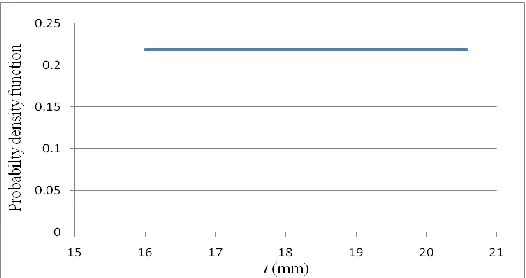
By taking required number of terms, C can be divided into corresponding number of intervals between 0 and 1, and for each C corresponding t can be found using Eqn(5.2) and is shown in Fig.5.1. Then the square of the average thickness in Eqn(3.5) is replaced by average of squared thickness . In other words, the average thickness is replaced by its Root Mean Square (RMS) value. Here radius is treated as constant and average R is used.
Fig. 5.1 Thickness variation using Uniform Distribution
VI. OBSERVATIONS
1. Propagation pressure decreases with increase in both β and c/t values. But the rate of decrease is slow with increase in β when compared to that of c/t.
2. As the angular extension of corrosion increases Anti-Symmetric mode dominates. This phenomenon is expected as β reaches 180° the pipe is again an intact pipe with reduced thickness throughout which buckles in Anti-Symmetric mode only.
3. Present values are compared with the values published by Jianghong Xue (2005). Small difference is observed because in the present work, the average flow stress is taken different at different hinges which is more accurate.
4. With increase in angular extension of corrosion the propagation pressure decreases. For higher depth of corrosion (c/t value) the decrease in propagation pressure is very rapid
VII. CONCLUSIONS OF WORK
1. For all values of β normalized propagation curves approximately follows the line joining the points (0, 1) and (1, 0). The mathematical equation of the line can be represented as “ɳ + c/t = 1”. By using this
equation an approximate value of propagation pressure can be found out.
2. The minimum required number of readings to find the propagation pressure accurately is 360 for both intact and corroded pipe line.
3. Average radius of the middle surface can be taken as constant when thickness is considered as random. 4. For any given thickness variation of a corroded pipe Fourier approximation can be made and propagation
pressure can be found using the propagation pressure formula for intact pipe by replacing t2
5. Calculating propagation pressure using thickness variation is especially useful for practical purpose where the angular extension and relative depth of corrosion is small like pitting corrosion and for the case when the angular extension of corrosion is large like erosion.
6. As the difference between propagation pressures calculated using normal distribution and using uniform distribution is very small, calculation of propagation pressure using thickness variation can be applied to any real situation even though it is checked here only for uniform distribution.
VIII. SUGGESTION FOR FUTURE WORK
1. Unsymmetric corrosion can be considered and applicability of using thickness variation for calculating propagation pressure can be studied which is more realistic
2. Three dimensional models of thickness variation can be formed and effect on buckling propagation pressure can be studied
REFERENCES
[1]. “Submarine pipeline systems (DNV-OS-F101)”, offshore standard, Det Norske Veritas, Norway, October 2007.
[2]. Palmer AC, Martin JH, “Buckle propagation in submarine pipelines. Nature” Vol. 254, March 1975, pp 46–48.
[3]. J. Xue, M. S. Hoo Fatt, “Propagating buckles in corroded pipelines”, Marine Structures, Vol. 14, Feb. 2001, pp 571–592.
[4]. J. Xue, M. S. Hoo Fatt, “Buckling of a non-uniform, long cylindrical shell subjected to external hydrostatic pressure”, Engineering Structures, Vol. 24, 2002, pp 1027–1034.
[5]. J. Xue, M. S. Hoo Fatt, “Symmetric and anti-symmetric buckle propagation modes in subsea corroded pipelines”, Marine Structures, Vol. 18, Aug. 2005, pp 43–61.
[6]. Fuat Kara, “Effect of thickness variation on collapse pressure of seamless pipes”, Ocean Engineering, Vol. 37, 2010, pp 998–1006.
[7]. Kyriakides.s, Corona.E, “Mechanics of offshore pipelines, Volume 1: Buckling and collapse”, Elsevier, Slovenia, 2007.
[8]. Ellenberger.P, “Piping systems and pipeline”, McGraw-Hill, 2005.
[9]. George A.Antaki, Piping and Pipeline Engineering: Design, Construction, Maintenance, Integrity, and Repair, ISBN 0-203-91115-6, Marcel Dekker, 2003.
[10].“Pipeline engineering manual: Design and Engineering practice (DEP 31.40.00.10-Gen)”, Companies of the royal Dutch/shell group, November 1993.
[11].“Gas transmission and distribution piping systems (ASME B31.8-2003)”, The American Society of Mechanical Engineers, U.S.A, Feb 2004.