ATLAS and CMS
DuccioAbbaneo1,2,a 1CERN, Geneva, Switzerland
2For the ATLAS and CMS Collaborations
Abstract.The High-Luminosity operation of the LHC poses unprecedented challenges for the design of the upgraded trackers of ATLAS [1] and CMS [2]. The stringent require-ments imposed by the high particle density and integrated fluence reduce the phase-space of valid technical solutions, inducing both collaborations to design “all-silicon” trackers. On the other hand constraints and requirements coming for the rest of the detector lead to some different choices, especially for the outer trackers. The main requirements for the two tracking systems are reviewed, discussing the implications for the detector designs and layout, and explaining why some of the technical choices remain different in the two experiments. To conclude, some expected performance figures for the two tracking systems are presented.
1 Requirements for the High-Luminosity LHC tracking systems
1.1 Requirements from higher particle rates
A major challenge for the design of the HL-LHC trackers is the target integrated luminosity of 3000 fb−1, which translates to unprecedented requirements in terms of radiation tolerance, particularly difficult to meet for sensors and on-detector electronics. The outer trackers will have to operate with unspoiled performance throughout the high luminosity program, planned for the decade 2026−2035, while it is conceivable that the inner parts of the pixel detectors could be replaced during a long shutdown, if the radiation tolerance requirements cannot be fulfilled.
ATLAS and CMS have performed detailed FLUKA [3] simulations to estimate the radiation ex-posure of the different detector regions, obtaining consistent results (Figure1). The estimated levels are about one order of magnitude higher compared to the requirements that were used for the design of the existing trackers [4–7], reaching levels of 1016particles per cm2in the innermost pixel regions. The particle fluence depends essentially onr(the distance from the beam axis), while the variation withz(the distance from the nominal average collision point, along the beam axis) is very moderate.
When translating such radiation levels into requirements for the design of the tracking subdetec-tors, it should be noted that the boundary between the outer tracker and the pixel detector is located at a radius of about 350 mm in ATLAS and 200 mm in CMS. Furthermore, in the present tracker upgrade layouts the first pixel layer is located at 39 mm in ATLAS and at 29 mm in CMS, which translates to
Figure 1. Integrated particle fluence in 1 MeV neutrons equivalent per cm2, for the CMS [8] and ATLAS [9] phase-2 trackers. The estimates shown correspond to a total luminosity of 3000 fb−1of 14 TeV pp collisions.
nearly a factor of two difference in hit rates and integrated particle fluence per unit area. Some of the reasons for these differences will be discussed below.
The other basic requirement for the high-luminosity operation is the ability to maintain efficient tracking in a high-density particle environment. The experience with the present detectors shows that efficient tracking with low fake rate can be achieved if the channel occupancy does not exceed the 1% level. ATLAS and CMS are designing their trackers to operate with up to 200 pile-up collisions per bunch crossing, which requires a granularity between 5 and 10 times higher than that of the present trackers.
1.2 Requirements from first-level trigger
Besides the fundamental requirements directly linked to the increased particle rates in the tracking detectors, ATLAS and CMS also need to improve their first level trigger decision1, in order to fully
profit from the higher luminosity. The enhancement of the trigger performance involves both a higher output rate of interesting events and an improved discriminating power of the event selection, which is more challenging in high pileup. Improved discriminating power will be achieved by using more information for the trigger decision, with a longer latency available for its processing. ATLAS and CMS plan to enhance the first level trigger rate and latency to the figures shown in Table1, which are the new requirements for front-end electronics of the tracking systems.
In addition to the increased trigger rate and latency, CMS has chosen to also provide tracking in-formation for the first-level trigger decision, implying that the tracker will send out some inin-formation at every bunch crossing. The different design choice is to some extent motivated by different boundary conditions in the two detectors (ATLAS has higher-granularity information from the calorimeters in the first-level trigger, while CMS has a stronger magnetic field, which helps for the specific imple-mentation chosen), and has in turn led to several differences in the design of the upgraded trackers.
Table 1.Planned increase of output rate and latency for the first-level trigger decision in ATLAS and CMS.
ATLAS 100 kHz −→ 1000 kHz 2.5μs −→ 6.0μs
CMS 100 kHz −→ 750 kHz 3.2μs −→ 12.8μs
1N.B.: The first-level trigger is called Level-0 in ATLAS and Level-1 in CMS.
DOI: 10.1051/
,
127 12700002
EPJ Web of Conferences 00002 (2016) epjconf/2016
Figure 2. Possible layout of the ATLAS (a) and CMS (b) upgraded tracking systems. In the ATLAS tracker the boundary between outer tracker and pixel detector is located at about 350 mm, while in CMS it is located at 200 mm.
1.3 Other improvements
Both ATLAS and CMS are planning to extend the rapidity acceptance of their tracking systems up to about|η|=4. Tracking in the very forward region allows to assign forward jets to primary vertices, which improves performance in vector boson fusion and vector boson scattering physics. The rapidity extension concerns mostly the layout of the pixel detectors, with relevant implications on the detector mechanics and arrangement of the services.
The material in the tracking volume is a major limitation for the performance of the present de-tectors, affecting not only tracking but also the global event reconstruction. Reducing the amount of material in the upgraded trackers is a vital goal, although the requirements of highly enhanced functionalities mentioned above make such goal challenging to achieve.
ATLAS and CMS are still optimising the layouts of the tracking systems that will have to fulfill the requirements discussed. Two of the layouts under consideration are shown in Figure2. For the CMS outer tracker, the layout shown is the baseline presented in the upgrade Technical Proposal [8], the collaboration is however also studying a different option with progressively tilted modules in the inner barrel layers. The layouts of the pixel detectors are still in the speculative phase for both collaborations.
2 Outer trackers
2.1 Tracker input to first-level trigger in CMS
The CMS tracker will provide information at each bunch crossing, in order to contribute to the first-level trigger decision. Such functionality relies upon local data reduction in the front-end electronics, in order to limit the volume of data that are sent out at 40 MHz. This is achieved with modules that are capable of rejecting signals from particles below a certainpT threshold, referred to as “pT mod-ules” [10–12]. The modules are composed by two closely-spaced sensors read out by a common set of front-end ASICs, that correlate the signals in the two sensors and select the pairs (“stubs”) compatible with particles above the chosenpTthreshold (Figure3). A threshold of around 2 GeV corresponds to a data volume reduction of roughly one order of magnitude, which is sufficient to enable transmission of the stubs at 40 MHz, while all other signals are stored in the front-end pipelines and read out when a trigger signal is received.
Figure 3.(a) Correlation of signals in closely-spaced sensors enables rejection of low-pTparticles; the channels shown in light green represent the “selection window” to define an accepted “stub”. (b) The same transverse momentum corresponds to a larger distance between the two signals at large radii for a given sensor spacing. (c) For the end-cap disks, a larger spacing between the sensors is needed to achieve the same discriminating power as in the barrel at the same radius. The acceptance window can therefore be tuned along with a few different values of sensor spacing to achieve the desiredpTfiltering in different regions of the detector. For a realistic pitch of about 100μm, sufficientpTresolution can be achieved down to a radius of about 200 mm, thanks to the 3.8 T magnetic field of CMS.
coordinate. For this reason two versions ofpT modules have been realized: 2–Strip (2S) modules
and Pixel–Strip (PS) modules (Figure 4). In PS modules one of the two sensors is segmented into
macro-pixels of about 1.5 mm length, providing also a precise measurement of thezcoordinate. The
main parameters of 2S and PS modules are summarized in Table2. The choice of pitch of 90μm
and 100μm are driven by limitations in the line density on the hybrid for the 2S module, and on the bump density of the C4 technology for the PS module. PS modules are deployed in the first three layers of the outer tracker, in the radial region of 200–600 mm (blue in the sketch of Figure2b), while 2S modules are deployed in the outermost three layers, in the radial region above 600 mm (red in
the sketch of Figure2b). Thezcoordinates provided by the three PS layers enable some level of
primary vertex discrimination for trigger tracks that do not have pixel coordinates, hence the interest to extend the range of PS layers towards low radii, up to the limit where the stubpTresolution remains acceptable.
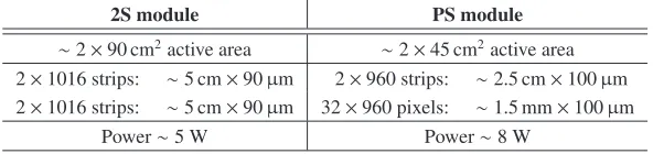
Table 2.Main parameters of the 2S module and the PS module of the CMS tracker.
2S module PS module
∼2×90 cm2active area ∼2×45 cm2active area 2×10¹⁶ strips: ∼5 cm×90μm 2×960 strips: ∼2.5 cm×100μm 2×10¹⁶ strips: ∼5 cm×90μm 32×960 pixels: ∼1.5 mm×100μm
Power∼5 W Power∼8 W
DOI: 10.1051/
,
127 12700002
EPJ Web of Conferences 00002 (2016) epjconf/2016
Figure 4. Silicon modules for the CMS tracker. 2S modules are composed of two strip sensors superimposed, PS modules of one strip sensor and one pixelated sensors. In the 2S module, the sensors are read out from the sides, where high-density flex hybrids bring the signals from both sensors to a common set of readout ASICs (CBC, CMS Binary Chip), as shown in the rightmost sketch. In PS modules, one of the two sensors is pixelated, and read out by a dedicated Macro-pixel ASIC (MPA). Also in this case a flex hybrid provides the connectivity between the MPA and the Short-Strip ASIC (SSA), reading out the strip sensor.
2.2 Modules and structures in ATLAS
For the barrel region, ATLAS has designed modules with similar strip lengths as CMS (48 mm and 24 mm for the outer and inner layers, respectively), but could afford a smaller pitch of 75μm, since the readout electronics collects signals from one sensor only. The readout hybrid is located on top of the sensor (Figure5a), which avoids large inactive area at the edge of the modules, that can therefore be abutted on the same surface with minimal inefficiency in between.
Barrel layers are composed of “staves” (Figure5c), each carrying two rows of modules on the two sides. Top and bottom modules have the strips tilted by±20 mrad with respect to thez-axis, hence providing also a precise measurement of thezcoordinate.
In the end-caps, modules are arranged on “petals” (Figure5b) that follow the same concept as the barrel staves. Several different sensor designs and variants of hybrid circuits are needed to cover the wedge-shaped surface with abutted modules. The granularity is similar to the barrel, with a typical pitch of 75–80μm and strip lengths of 20–30 mm in the inner rings, and 40–60 mm in the outer rings. On one side of the petal modules have radial strips, providing theφcoordinate, while on the other side the strips are tilted by 40 mrad, hence measuring alsor.
2.3 Modules and structures in CMS
ThepTmodules discussed in Section2.1populate the entire volume of the CMS outer tracker. The
Figure 5. ATLAS silicon modules feature the readout hybrid integrated on top of the sensors, hence avoiding inactive area on the sides (a). In the barrel staves (c), two rows of modules are abutted on each side of the mechanical structure. A similar concept is implemented in the end-cap petals, where different sensor and hybrid versions are needed to cover the wedge-shaped surface.
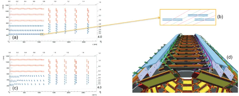
Figure 6.In the flat barrel layout (a) PS modules at the edge of the inner barrel layers have a large geometrical inefficiency for on-board stub finding (b): while the inefficiency at the edge of the modules can be compensated by implementing large overlaps between consecutive modules inz, the inefficiency in the center is irrecoverable (indicated by the red tracks). To overcome the problem, an alternative layout with progressively tilted modules (c) is under study. The design of the mechanics for the tilted layout is well advanced (d).
In the outer three layers of the barrel the effect of stub finding inefficiency is much less severe because the incidence angle of particles is less pronounced , the sensor spacing at those radii is smaller,
and the modules are twice as long on thezside. Modules are mounted on “ladders”, where overlap
in thezview is achieved by placing the modules at different radii (Figure7a). Alongφ, consecutive ladders are again staggered inr, hence a hermetic barrel layer is formed by modules located at four different radii.
DOI: 10.1051/
,
127 12700002
EPJ Web of Conferences 00002 (2016) epjconf/2016
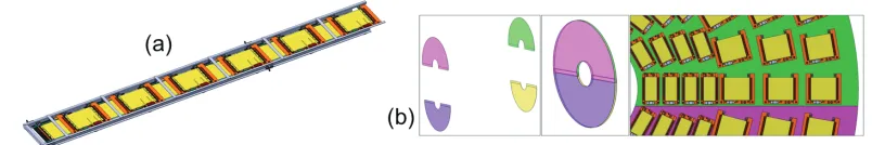
Figure 7. In the ladders of the CMS outer barrel (a), modules are mounted at two different radii in order to implementz overlap. In the end-caps, the same rectangular modules are arranged on the four surfaces of a double-disk structure (b).
In the end-cap, due to the large radial extension (from 200 mm to nearly 1100 mm) and the small size of PS modules, the use of wedge-shaped modules would lead to an impractical large number of sensor and hybrid varieties. Therefore the same rectangular modules used in the barrel are arranged on a double-disk structure: modules located at a given radius are mounted alternately on the two sides of a disk with overlap inφ, forming a hermetic ring; consecutive rings alongrare mounted on different disks, hence also achieving radial overlap. Similarly to the barrel, a hermetic disk surface is achieved with modules mounted at four differentzlocations.
3 Pixel detectors
The high-luminosity operation implies extreme challenges for the design of the pixel detectors in terms of radiation tolerance of sensors and readout electronics, as well as data volume to be stored in the front-end pipelines and sent out at high trigger rates. In order to cope with the reduced charge in the sensors, a readout chip with small cell size and low detector threshold is required. ATLAS and CMS are carrying out a common development in the framework of RD53 [13], to design a pixel chip with 2500μm2cell size, in 65 nm CMOS technology.
Despite the common development for the front-end ASIC, some relevant differences remain in
the layout of the two pixel detectors, in their present stage of development. Besides the different outer boundary discussed above, motivated by the fact that CMS implements macro-pixels in the intermediate radial range, in the current designs the inner boundary is also different, with the CMS pixel detector featuring a first layer at 29 mm average radius, while the ATLAS detector has the first layer at 39 mm. The difference is quite relevant as it translates to nearly a factor of two difference in hit rates and particle fluence per unit surface. The difference is partially justified by the fact that the CMS pixel detetctor can be installed and extracted with the beam pipe in place, and is removed in the occasion of a beam pipe bakeout; hence it can be located as close as allowed by the mechanical tolerances. In comparison, in ATLAS the first layer of the pixel detector is mounted directly onto the beam pipe, which requires a certain thickness of insulation material for the beam pipe bakeout. CMS maintains as its design target to have a first layer at about 30 mm also for the high luminosity operation, while ATLAS is exploring the possibility of reducing the radius compared to the current design.
Another topic under study is the optimal pixel aspect ratio, for the assumed pixel surface of
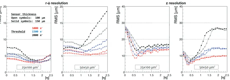
2500μm2. CMS has studied the case of the most challenging barrel layer 1, comparing ther−φ
Figure 8.Comparison of single hit resolutions inr−φandzobtained in the first pixel barrel layer with square and rectangular pixels, for different assumptions on sensor thickness and detection threshold. Open and solid markers correspond to 100μm and 150μm silicon thickness, respectively; red markers correspond to a threshold of 1000 e−, blue markers 1500 e−and black markers 2000 e−. Square pixels offer betterzresolution in the central region, while rectangular pixels give in general better performance in the other cases, and are less demanding on the chip threshold. These results are obtained with the flat barrel geometry of Figure2b, and the simulation corresponds to unirradiated sensors.
forward part of the barrel, rectangular pixels of 25×100μm2offer better resolution, while being less demanding in terms of detection threshold and required bandwidth (which is particularly relevant for a first layer located at a radius of 30 mm). ATLAS instead is focussing on the use of square pixels studying how to exploit the correlation between cluster length and track incident angle: details on these studies can be found in [14].
Concerning the overall layout, CMS has so far used the geometry shown in Figure2b, derived
from the “phase-1” detector with added disks to extend the rapidity coverage. It is however known that modifications to this geometry will be needed, because the detector insertion mechanism requires
a larger opening in the forward part, beyondz≈1500 mm. The boundary between pixel detector and
outer tracker will have to be moved to a higher radius in that region.
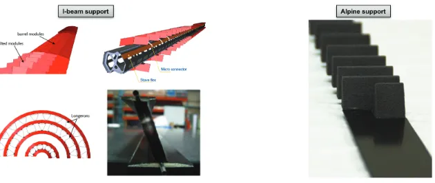
ATLAS has several pixel detector concepts under study. As an alternative to the flat barrel layout, two different options implementing progressively tilted modules are investigated, and could be de-ployed in some or all of the layers, as shown in the sketches of Figure9. The design of both versions of the tilted geometry is well advanced, with realistic prototypes already built (Figure10).
4 Expected performance
Both collaborations have produced performance estimates for the tracker concepts under study. In Figure11the efficiency as a function of transverse momentum is shown for the ATLAS tracker, along
with the muonpT resolution and the fraction of mis-reconstructed tracks. The solid black markers
correspond to the baseline layout, offering good performance up to|η|<4, while the other markers correspond to cost-saving options with reduced coverage.
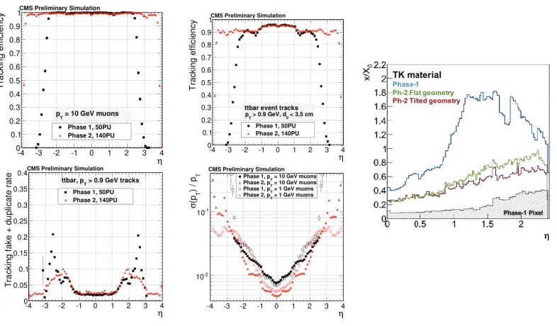
In Figure12the expected performance of the CMS upgraded tracker at 140 pileup is compared to
the “phase-1” detector at 50 pileup. The upgraded tracker provides equivalent or better performance in the higher pileup conditions within the common acceptance range, while extending the acceptance
DOI: 10.1051/
,
127 12700002
EPJ Web of Conferences 00002 (2016) epjconf/2016
Figure 9. Layout of the ATLAS tracker with three different options for the pixel barrel: a geometry with flat layers (a), an option where the first two layers implement progressively tilted modules (b), and a third version with tilted geometry in all layers (c).
Figure 10.Two different options are being developed in ATLAS [15] to implement tilted modules in pixel barrel layers. In the I-beam concept (left) mechanical supports are shared between neighbouring layers, offering the possibility to realize lightweight structures of high stiffness, particularly suitable for long layers. The Alpine concept (right) is a straightforward adaptation of the flat stave concept, where carbon-fiber wedges are added to support modules with the desired tilt angle.
up to nearly|η|=4. The amount of material of the outer tracker is reduced by about a factor of two compared to the present tracker, despite the highly enhanced functionalities.
Another important aspect for the CMS tracker is the performance in the reconstruction of tracks for the first-level trigger, which was the subject of other contributions to this workshop [16].
5 Conclusions
The high-luminosity operation of the LHC entails unprecedented requirements in terms of particle density and integrated fluence for the trackers of ATLAS and CMS. Such requirements limit the phase-space of valid technical solutions, inducing both Collaborations to design “all-silicon” trackers. The challenge is particularly difficult for the pixel detectors, where ATLAS and CMS are carrying out a common development for the readout chip, in the framework of RD53.
CMS has chosen to implement tracking in the first-level trigger decision, which has driven sev-eral specific design choices, especially in the outer tracker: the implementation ofpT modules limits
Figure 11.Main performance figures for the upgraded ATLAS tracker [15]. The baseline layout, corresponding to the solid black markers, provides excellent tracking performance up to|η|=4. The other markers correspond to various cost-saving options with reduced coverage.
boundary between outer tracker and pixel detector is pushed to lower radii to achieve primary ver-tex discrimination in trigger tracks; the large radial extension and half-size PS module disfavour the development of wedge-shaped modules for the end-cap; the need of mitigating the geometrical inef-ficiency for stub finding has motivated the development of the tilted layout for the inner barrel. The sketch of Figure13illustrates the cascade of implications.
The available performance estimates indicate that both detectors will provide efficient tracking in high pileup conditions, and at the same time offer improved resolution and extended acceptance.
While the design of the outer trackers is relatively advanced, layout options for the pixel detectors are still being explored, and further developments are underway.
DOI: 10.1051/
,
127 12700002
EPJ Web of Conferences 00002 (2016) epjconf/2016
Figure 12. The performance of the upgraded CMS tracker in 140 pileup events is compared to the phase-1 tracker in 50 pileup events [8]. The upgraded tracker provides similar tracking efficiency and better resolution and fake rate, plus extended acceptance. The amount of material in the outer tracker is substantially reduced, and the tilted geometry for the inner barrel offers an additional reduction compared to the flat geometry. N.B.: A material estimate for the upgraded pixel detector is not yet available, therefore the phase-1 material distribution is used in this plot.
References
[1] The ATLAS Collaboration, JINST3, S08003 (2008),
http://stacks.iop.org/1748-0221/3/i=08/a=S08003
[2] The CMS Collaboration, JINST3, S08004 (2008),
http://stacks.iop.org/1748-0221/3/i=08/a=S08004
[3] A. Ferrari, P.R. Sala, A. Fassò, J. Ranft, Tech. Rep. CERN-2005-010, CERN, Geneva, Switzerland (2005),https://cds.cern.ch/record/898301
[4] The CMS Collaboration, Tech. Rep. CERN-LHCC-1998-006, CERN, Geneva, Switzerland (1998),https://cds.cern.ch/record/368412
[5] The CMS Collaboration, Tech. Rep. CERN-LHCC-2000-016, CERN, Geneva, Switzerland (2000),https://cds.cern.ch/record/490194
[6] The ATLAS Collaboration, Tech. Rep. CERN-LHCC-1997-016, CERN, Geneva, Switzerland (1997),https://cds.cern.ch/record/331063
[7] The ATLAS Collaboration, Tech. Rep. CERN-LHCC-1997-017, CERN, Geneva, Switzerland (1997),https://cds.cern.ch/record/331064
[8] The CMS Collaboration, Tech. Rep. CERN-LHCC-2015-010, CERN, Geneva, Switzerland (2015),https://cds.cern.ch/record/2020886
[9] The ATLAS Collaboration, Tech. Rep. CERN-LHCC-2012-022, CERN, Geneva, Switzerland (2012),https://cds.cern.ch/record/1502664
[10] C. Foudas, A. Rose, J. Jones, G. Hall (2005),https://arxiv.org/abs/physics/0510227
[11] G. Hall, M. Raymond, A. Rose, JINST5, C07012 (2010),
http://iopscience.iop.org/article/10.1088/1748-0221/9/10/C10034/meta
[12] M. Pesaresi, G. Hall, JINST5, C08003 (2010),
http://iopscience.iop.org/article/10.1088/1748-0221/5/08/C08003/meta
[13] J. Christiansen, M.L. Garcia-Sciveres (eds.), Tech. Rep. CERN-LHCC-2013-008, CERN, Geneva, Switzerland (2013),https://cds.cern.ch/record/1553467
[14] S. Viel et al., Nucl. Inst. & Meth. A831, 254 (2016),
http://www.sciencedirect.com/science/article/pii/S0168900216301346
[15] The ATLAS Collaboration, Tech. Rep. CERN-LHCC-2015-020, CERN, Geneva, Switzerland (2015),https://cds.cern.ch/record/2055248
[16] G. Fedi, these proceedings; L. Skinnari, these proceedings
DOI: 10.1051/ ,
127 12700002
EPJ Web of Conferences 00002 (2016) epjconf/2016