Fingering induced by a solid sphere impact to viscous fluid
Hiroaki KatsuragiaDepartment of Earth and Environmental Sciences, Nagoya University, Furocho, Chikusa, Nagoya 464-8601, Japan
Abstract. The number of splashed fingers generated by a solid projectile’s impact onto a viscous liquid layer is experimentally studied. A steel sphere is dropped onto a viscous liquid pool. Then, a fingering instability occurs around the crater’s rim, depending on the experimental conditions such as projectile’s inertia and the viscosity of the target liquid. When the impact inertia is not sufficient, any fingering structure cannot be observed. Contrastively, if the impact inertia is too much, the random splashing is induced and the counting of fingers becomes difficult. The clear fingering instability is observable in between these two regimes. The number of fingersNis counted by using high-speed video data. The scaling ofNis discussed on the basis of dimensionless numbers. By assuming Rayleigh-Taylor instability, scaling laws forNcan be derived using Reynolds numberRe, Weber numberWe, and Froude numberFr. Particularly, the scalingN=(ρrFr)1/4We1/2/33/4is obtained for the
gravity-dominant cratering regime, whereρris the density ratio between a projectile and a target. Although the
experimental data considerably scatters, the scaling law is consistent with the global trend of the data behavior. Using one of the scaling laws, planetary nano crater’s rim structure is also evaluated.
1 Introduction
Since Worthington’s pioneering work for the splashing of fluid impact [1], the impact splashing has been studied in-tensively by many physicists. Recent developments of the numerical computation and the high-speed imaging enable us to reveal the detailed dynamics of the fluid impact [2– 4]. Particularly, a liquid droplet impact either onto a liq-uid pool or a hard floor has been studied well so far [2]. A solid sphere impact to a non-Newtonian target fluid has been also investigated experimentally [5, 6]. Furthermore, some recent studies have concerned granular target im-pacts as well as fluid target imim-pacts. Examples include a solid sphere’s impact to a granular bed [7–12], a liquid droplet impact to a granular bed [13, 14], and a vortex ring impact to a granular bed [15].
In spite of these recent efforts for the soft matter im-pact, fingering instability by the impact between a solid sphere and a liquid pool has not been studied well. This is a little surprising because it is probably one of the sim-plest setups. So far, the study of fingering instability has been almost restricted within a droplet impact. However, natural fingering instability is not limited in the macro-scopic droplet impact. For instance, micromacro-scopic impact cratering has been found in the space environment. Naka-mura et al. have found wavy rim structures of tiny (100 nm order) craters on the sample returned from the asteroid Itokawa [16]. This crater rim structure reminds us the fin-gering instability. The petal-like crater’s rim structure has been also found in the droplet impact to a granular bed [13, 14]. From the high-speed video data taken in the experi-ments, we have confirmed that the petal-like structure is caused by the fingering instability of the impacting droplet. Petal-like ejecta blanket structure called Rampart crater can be also found in the Martian surface and a laboratory experiments of the hypervelocity impact to a muddy
tar-a e-mail:[email protected]
get [17]. Such simple laboratory experiments might be use-ful to discuss the origin of widely variated natural craters shapes. Note that, however, surfaces of actual astronomi-cal objects do not consist of liquid. They are rather cov-ered with regolith. Moreover, Itokawa’s returned samples, on which nano craters were found, are solid (not liquid). Thus the real craters morphologies might not directly link to the liquid impact. However, we believe that the funda-mental study of the liquid impact could be a first step to understand the variety of complex craters morphologies.
To classify the physical origins of various fingering-like structures in soft matter impacts, fundamental investi-gations on the fingering instability with various projectiles and targets are necessary. For example, viscoelastic prop-erty of the target material might play a certain role in the very high-speed impact in which the melting of the tar-get could occur. As a first step, we should begin with the simplest setup. Therefore, we carry out one of the simplest impact experiments—a steel sphere impact onto a viscous liquid—in order to approach a fundamental law of the fin-gering instability. Particularly, we analyze the experimen-tal data by combining the models of liquid deformation and Rayleigh-Taylor instability. Using the derived model, we speculate the impact velocity to make astronomical nano craters accompanied with wavy rim structure. Then the limitations for this consideration are also discussed finally.
2 Experimental
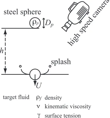
We build a simple experimental apparatus as schematically shown in figure 1. A steel sphere in diameterDp=3, 6.35, or 8 (mm) is held by an electromagnet. Then it is dropped from a certain heighthto commence a free fall. The free-fall height h ranges from 20 to 605 (mm) corresponding to the impact velocity ofU = 0.2−3.6 (m/s). This free-fall drop system is basically identical to that used in our previous experiment on the agar gel impact [6]. Density C
Owned by the authors, published by EDP Sciences, 2015
h
high speed camera
target fluid
steel sphere
D
pρ
fρ
pν
γ
surface tension kinematic viscositysplash
U
density
Fig. 1.A schematic drawing of the experimental apparatus. A stainless steel sphere is dropped onto a viscous liquid pool by free fall. The splashing is taken by a high-speed camera.
of the steel sphere is ρp = 8.0× 10³ (kg/m3). We em-ploy silicone oil (Shin-Etsu Chemical Co., Ltd.) or distilled water as target fluids. The range of kinematic viscosityν and surface tensionγof target fluids are 0.65 ≤ ν ≤ 200 (×10−6 m2/s(=cSt)) and 16 ≤ γ ≤ 72 (×10−3 N/m), re-spectively. The density of fluid ranges 0.8 ≤ ρf ≤ 1.0 (×103 kg/m3). Namely, main control parameters are the impact inertia and the target viscosity. Target surface ten-sion and density are varied slightly. Actually, we have used the viscoelastic fluid target as well. However, we could not observe any fingering instability for viscoelastic tar-gets, at least in the range of current experimental condition. Much larger impact inertia is probably required to induce the fingering instability in the viscoelastic impact. Thus we are going to focus only on the viscous target case, in this study. Impact and splashing are captured by a high-speed camera (Photron SA-5) at 5,000 fps. All the experiments are performed under the atmospheric pressure environment (101 kPa).
3 Results and discussion
Typical snapshots of the experimental results are presented in figure 2. When the target viscosity is large, any fingering instability cannot be observed. Such an example (ν= 120 cSt) is shown in figure 2(a). To induce the fingering insta-bility on a very viscous target, much larger impact inertia is necessary. On the other hand, we can confirm the clear fin-gering instability for an impact to a less viscous target (fig-ure 2(b);ν=0.89 cSt). When the impact inertia increases more, random splashing is induced as shown in figure 2(c). In this regime, it is hard to count the number of fingers from the raw video data. Perhaps, this limit comes from the limitations of temporal and spatial resolutions of the images taken by the high-speed camera. Much higher reso-lution images might enable us to study this random regime. Since we are interested in the typical fingering structure,
Fig. 2.Typical snapshots of the impacts: (a) no-fingering case (d =8 mm,ν =120 cSt, andh=240 mm); (b) fingering case (d = 6.35 mm,ν = 0.89 cSt, and h = 120 mm); (c) random splashing (d=6.35 mm,ν=0.65 cSt, andh=605 mm).
we restricted ourselves to the transient regime in which the clear fingering structure can be observed.
ρ
" #$%&'($%&)& *)+,%&' "ρ
- .#$%&)($%&'/α
*0, *1, *2,
α
α
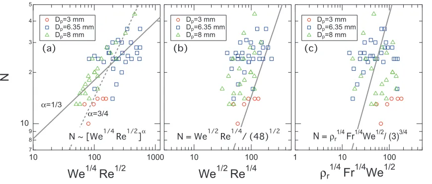
Fig. 3.Scaling results of the counted fingers numberNby (a) impact Reynolds numberReI, (b) droplet-deformation-included
Rayleigh-Taylor instability, and (c) crater-deformation-based Rayleigh-Rayleigh-Taylor instability. The solid and dashed lines in (a) indicate the scaling N ∼ReI1/3 andN ∼ ReI3/4, respectively. The solid line in (b) representsN =We1/2Re1/4/4
√
3. The solid line in (c) corresponds to N=(ρrFr)1/4We1/2/33/4. While these scaling laws capture the global trend of data behavior, the data dispersion is significantly large.
3.1 Impact Reynolds number
First, the simple scaling analysis is tried by combining two possibly relevant dimensionless numbers: Weber number We = ρfU2Dp/γ and Reynolds number Re = UDp/ν. Here we introduce the impact Reynolds number [18]. Im-pact Reynolds number has been derived by considering the representative length scaleL =[ν(mp/γ)1/2]1/2, where mp is the sphere’s mass. The characteristic timescaletγ =
(mp/γ)1/2 comes from the spring-like effect of the liquid surface tension. And L indicates the length scale of mo-mentum diffusion bytγandν. Then, the impact Reynolds
numberReI is defined as
ReI = UL
ν =We1/4Re1/2. (1)
Marmanis and Thoroddsen have shown that the number of fingers by a droplet impacting to a hard floor can be scaled byN ∼ReI3/4[18]. In figure 3(a), the counted result ofN as a function ofReIfor the current experiment is displayed. Although the data considerably scatter due to the difficulty of fingers-counting, here we apply the data fitting toReI scaling. Then, as shown in figure 3(a), the data can be fitted by a scaling,
N∼ReIα. (2)
The obtained scaling exponentα = 1/3 is different from the previously obtained droplet impact experiment,α = 3/4 [18]. Solid and dashed lines in Fgi. 3(a) correspond to N ∼ ReI1/3 andN ∼ ReI3/4, respectively. This difference might come from the geometry difference. Whileα=3/4 was obtained for the impacting droplet case,α= 1/3 cor-responds to the case that a hard projectile impact to a liquid target. Moreover, the obtained scaling means very weak WeandRedependences:N∼We1/12Re1/6. Such small ex-ponents are not so useful for the scaling analysis. It is hard to discuss the underlying physical mechanism on the basis of these small exponents. The data can be fitted only be-cause the model of Eq. (2) has two free fitting parameters.
3.2 Rayleigh-Taylor instability
Next, Rayleigh-Taylor instability is considered as an alter-native candidate to explain the fingering. Rayleigh-Taylor instability is induced at an interface of denser and lighter fluids when the denser one is accelerated toward the lighter one. The capillary-based characteristic wave numberkfor the Rayleigh-Taylor instability can be computed as [19– 21],
k=
(ρh−ρl)a
3γ , (3)
whereρh,ρl, andaare the density of denser fluid, that of lighter fluid, and the applied acceleration, respectively. By assumingρf =ρhρlandaU2/Dp,kcan be rewritten as k = We1/2/√3D
p. If this instability is induced at the perimeter of a circle in diameterDc, the number of fingers Nis written as,
N= Dc 2√3Dp
We1/2. (4)
By considering a liquid droplet impact onto a hard floor, the maximally deformed droplet diameterDcat viscosity-dominant regime can be approximated by [22–24],
Dc 1 2DpRe
1/4. (5)
Here,Dpcorresponds to the initial droplet diameter. Sub-stituting Eq. (5) to Eq. (4), one can obtain a form of N as [24],
N= 1 4√3We
1/2Re1/4. (6)
the scaling in figure 3(b) might look worse than that in fig-ure 3(a), note that the scaling of Eq. (6) does not include any fitting parameter.
To improve the scaling more, here we consider the crater cavity model [25, 26]. Let us assume that the projectile’s kinetic energyEkis mainly consumed by the potential en-ergy of the crater’s cavityEcav. The cavity potential energy Ecavis calculated asEcav =πρfgD4c/64 [25]. By equating Ecavand the impacting kinetic energyEk= πρpD3pU2/12, the cavity diamaterDcis obtained as,
Dc=2 ⎛ ⎜⎜⎜⎜⎜ ⎝ρpD
3 pU2 3ρfg
⎞ ⎟⎟⎟⎟⎟ ⎠
1/4 =2Dp
ρp 3ρf
Fr 1/4
. (7)
Substituting Eq. (7) to Eq. (4), a scaling form is obtained as,
N=3−3ρrFr 1/4
We1/2, (8)
where Fr = U2/gD
p is Froude number and ρr = ρp/ρf is the density ratio between a projectile and a target. This form looks similar to Eq. (6);Reis replaced by ρrFrin terms of the scaling relation. While the dominant effect in Eq. (6) is viscosity, the gravity plays an essential role in Eq. (8). This implies that the scaling of Eq. (8) is valid for the gravity-dominant cratering regime. In figure 3(c), the experimental data are compared with this scaling. The abscissa of figure 3(c) comes from the right-hand side of Eq. (8). Whereas the data still widely scatter, the scaling captures the global trend without any fitting parameter. Per-haps, the small projectile case (Dp = 3 mm) can be better explained by the viscosity-based scaling (Eq. (6)). Other data seem to agree with the gravity-dominant scaling. This fingering relates to the surface tension effect and we did not directly measure the surface tension value (i.e. we use cat-alogue data). Therefore the data contain large uncertainty. That is probably the reason why it is hard to reduce the relatively large data dispersion in all panels of figure 3. Moreover, the range ofWeswept by this study is not wide enough. To make the scaling relation sure, more systematic experiments with widely ranging dimensionless numbers must be carried out.
3.3 Application to the fingering of nano craters found on the asteroid Itokawa
In principle, we can estimate the impact conditions for var-ious (gravity-dominant) craters with fingering instability, by using Eq. (8). However, it is not easy to estimate the proper value of Fr particularly for the astronomical im-pacts. Instead, the crater dimensions are directly accessi-ble as far as the craters are observed. In such a situation, Eq. (4) is useful to evaluate the impact conditions. This scaling is based only on the Rayleigh-Taylor instability. It does not assume the dominant dynamics of the deforma-tion: e.g. viscosity, gravity, or strength.
Here, let us estimate the impact velocityUfor the wavy rim structure of nano craters found on Itokawa’s returned samples [16]. To this purpose, Eq. (4) is rewritten as,
U= 2N Dc
3Dpγ
ρf
. (9)
In order to compute a specific value of U, here we use physical properties of SiO2: ρf = 2000 kg/m3 andγ = 0.014 N/m [27]. In addition, N 7 and Dc 200 nm can be observed from the photos of nano craters [16]. As-sumingDp = Dc/2, which is a reasonable assumption for fluid impacts, we finally obtain U 100 m/s. If we as-sume a molten glass state for the target,γvalue is about one order of magnitude greater than the currently assumed value. However, the resultantUstill remains in the order of U =102 m/s. The assumptionD
p = Dc/2 actually means Fr 1 if we use Eq. (7). However, it is quite difficult to satisfy this condition under the very weak gravity like Itokawa. Thus, the crater diameterDcmust be determined rather by the target strengthY. By considering the energy balance betweenEcav,Y = πDc3T/12 andEk,Dcis written as,
Dc=Dp ρpU2
Y
. (10)
Then, the strengthY = 2.5 MPa is obtained from the con-ditionDp=Dc/2. We can even estimate the finite strength of the target in this framework. The existence of the finite strength implies that the target material should somehow be viscoplastic. Substituting Eq. (10) to Eq. (9), we obtain a form of the impact velocity in strength-dominant crater-ing regime as,
U= 12N 2γ
ρfDp 3/10
Y
ρp 1/5
. (11)
Since this estimate is based on the simple scaling anal-ysis, only the rough order estimate is possible. In terms of the order estimate, the above estimate might be reason-able. However, there are some severe problems that must be overcome to fully understand the impact causing the wavy nano craters rim. Such problems are briefly discussed below.
In general, the region of fingering instability depends on surrounding gas pressure [28] and wettability of the projectile [29] as well as impact inertia and properties of projectile and target. The droplet impact under vacuum condition cannot cause the fingering [28]. If the surface of projectile is hydrophilic, no-splashing is observed until the critical impact inertia [29]. These characteristics relate to the transition from the no-fingering to the clear-fingering states. While these effects might influence the value of pa-rameters at the transition point, we consider the scaling ex-ponent would not be affected. Furthermore, a recent work has revealed that the fingering of a droplet impact depends on the shape of the target [30]. In the current investiga-tion, we performed a very simple experiment and found thatNmight be scaled by the combination ofWe,Frand
ρr. This means that the crater deformation and the associ-ated Rayleigh-Taylor instability are the possible sources of the fingering pattern formation.
shape on the target surface just like Itokawa’s nano crater. However, much higher impact velocity and vacuum con-ditions are needed to study a viscoelastic or viscoplastic fingering. This is the important future problem.
4 Summary
We performed the low-velocity impact experiment with steel sphere projectiles and viscous target liquids. Milk-crown-like fingering can be observed in a particular pa-rameter regime. The number of fingers created by the im-pact was counted from the high-speed video images. The observed fingers numberN can be scaled by the relation N (ρrFr)1/4We1/2/33/4. This scaling is based on the Rayleigh-Taylor instability and the balance between the projectile’s kinetic energy and the target cavity’s poten-tial energy. While the scaling reveals a certain aspect of the fingering induced by the impact to soft targets, fur-ther studies are necessary to clarify the details of impact fingering instability. Using a Rayleigh-Taylor-based scal-ing (N DcWe1/2/2
√
3Dp), one can estimate the impact velocity for nano crater’s wavy rim found on samples re-turned from the asteroid Itokawa. Assuming the strength-dominant cratering, the strength of the target material can also be estimated. However, more careful estimate by con-sidering extreme conditions such as vacuum and low tem-perature is necessary to discuss the origin of wavy rim structures on Itokawa’s nano craters.
Acknowledgments
We would like to acknowledge S. Watanabe for introduc-ing the Itokawa’s nano crater shapes. This research has been partly supported by Grant for Basic Science Research Projects of Sumitomo Foundation, and JSPS KAKENHI #23654134 and #26610113.
References
1. A. M. Worthington, Philos. Trans. R. Soc. Lond. A 189(1897) 137.
2. A. L. Yarin, Annu. Rev. Fluid Mech.38(2006) 159. 3. C. Clanet, Annu. Rev. Fluid Mech.39(2007) 469. 4. S. T. Thoroddsen, T. G. Etoh, and K. Takehara, Annu.
Rev. Fluid Mech.40(2008) 257.
5. H. Tabuteau, D. Sikorski, S. J. de Vet, and J. R. de Bruyn, Phys. Rev. E84(2011) 031403.
6. K. Ara and H. Katsuragi, J. Appl. Phys.113 (2013) 063512.
7. J. S. Uehara, M. A. Ambroso, R. P. Ojha, and D. J. Durian, Phys. Rev. Lett.90(2003) 194301.
8. A. M. Walsh, K. E. Holloway, P. Habdas, and J. R. de Bruyn, Phys. Rev. Lett.91(2003) 104301.
9. H. Katsuragi and D. J. Durian, Nat. Phys. 3 (2007) 420.
10. H. Katsuragi and D. J. Durian, Phys. Rev. E87(2013) 052208.
11. J. O. Marston, E. Q. Li, and S. T. Thoroddsen, J. Fluid Mech.704(2012) 5.
12. J. R. Royer, E. I. Corwin, A. Flior, M-L. Cordero, M. L. Rivers, P. J. Eng, and H. M. Jaeger, Nat. Phys. 1 (2005) 164.
13. H. Katsuragi, Phys. Rev. Lett.104(2010) 218001. 14. H. Katsuragi, J. Fluid Mech.675(2011) 552.
15. N. Masuda, J. Yoshida, B. Ito, T. Furuya, and O. Sano, Fluid Dyn. Res.44(2012) 015501; J. Yoshida, N. Ma-suda, B. Ito, T. Furuya, and O. Sano, Fluid Dyn. Res. 44(2012) 015502.
16. E. Nakamura, A. Makishima, T. Moriguti, K. Kobayashi, R. Tanaka, T. Kunihiro, T. Tsujimori, C. Sakaguchi, H. Kitagawa, T. Ota, Y. Yachi, T. Yada, M. Abe, A. Fujimura, M. Ueno, T. Mukai, M. Yoshikawa, and J. Kawaguchi, PNAS109(2012) E624.
17. D. G. Gault and R. Greeley, Icarus34(1978) 486. 18. H. Marmanis and S. T. Thoroddsen, Phys. Fluids 8
(1996) 1344.
19. S. Chandrasekhar,Hydrodynamic and Hydromagnetic Stability, Oxford University Press, New York (1961). 20. A. R. Piriz, O. D. Cort´azar, J. J. L´opez Cela, N. A.
Tahir, Amer. J. Phys.74(2006) 1095.
21. A. Bret, Laser and Particle Beams29(2011) 255. 22. C. Mundo, M. Sommerfeld, C. Tropea, Int. J.
Multi-phase Flow,21(2) (1995) 151.
23. M. Pasandideh-Fard, Y. M. Qiao, S. Chandra, J. Mostaghimi, Phys. Fluids,8, 650 (1996)
24. R. Bhola and S. Chandra, J. Mater. Sci. 34 (1999) 4883.
25. O. G. Engel, J. Appl. Phys.37(1966) 1798. 26. O. G. Engel, J. Appl. Phys.38(1967) 3935.
27. J. Blum and R. Schr¨apler, Phys. Rev. Lett.93(2004) 115503.
28. L. Xu, W. Zhang, and S. R. Nagel, Phys. Rev. Lett.94 (2005) 184505.
29. C. Duez, C. Ybert, C. Clanet, and L. Bocquet, Nat. Phys.3(2007) 180.