Coin Based Mobile Charger
P.Soujanya, Y.Vamsikrishna, V.Siva Suresh, V.Srilatha
Asst. Professor, Department of ECE, Chalapathi Institute of Engineering and Technology, Lam, Guntur, AP, India
B.Tech, Department of ECE, Chalapathi Institute of Engineering and Technology, Lam, Guntur, AP, India
ABSTRACT: The coin based mobile charging system charges the mobile phones when the coin is inserted. This system is used by shop owners, rural people and can be implemented in the public places like railway stations, bus stand to provide mobile charging facility. So the coin acceptor [1] recognizes valid coins and then signals the Arduino for further action. If a valid coin is found, it signals the Arduino and then Arduino starts the mobile charging mechanism providing a 5V supply through a power supply section to the mobile phone. The Arduino starts a reverse countdown timer to display the charging time for that mobile phone. Further the user adds another coin, the Arduino adds to the currently remaining time and once again decrements the countdown. This system can be used for smart mobile charging at public places. This coin based mobile charging system will supply the enough amount of charge to the mobile phone and is available on demand in public places.
KEYWORDS: Coin acceptor, Arduino, LCD display, Relay
I. INTRODUCTION
This is the smart coin based mobile charging system that charges your mobile for particular amount of time on inserting a coin. The system is to be used by shop owners, public places like railway stations to provide mobile charging facility. So the system consists of a coin recognition module that recognizes valid coin is found it signals the microcontroller for further action [6]. If a valid coin is found it signals the microcontroller and microcontroller then starts the mobile charging mechanism providing a 5v supply through a power supply through a power supply section to the mobile phone, now systems also needs to monitor the amount of charging to be provided. So the system can be used for smart mobile charging at public places. Now a day’s students and many other people use the public transportation, people who are making every long journey in order attend business conventions, conferences, or for any private purpose don’t know their battery level is low and they often forget their charger at home or it in hotel room. Many critics argued that long distance travelling vehicles provides power points. Even through one or two power points are provided at a particular place in the vehicles it is not all sufficient for all passengers, therefore need to provide a public charging service is essential and coin based mobile charging are designed to solve these problem.[4]
II. PROPOSED SYSTEM
To overcome disadvantages mobile battery charging, we are going to implement Mobile battery charge on coin insertion system. The charging Time period is calculated by using Atmega328p microcontroller and after that microcontroller display the remaining time period. When Time period reaches to zero automatically power supply will cut by using relay circuit.
APPLICATIONS:
It is used for emergency charging purposes.
It can be installed railway stations, bus stops, villages and rural areas and public places. It can be installed in office and colleges for pay charging facility.
ADVANTAGES:
Small in size.
Cost of manufacture is less.
Flexibility of using in various applications. Installation is easy.
III. BLOCK DIAGRAM
Figure 2.1: Block diagram of coin based mobile charger
The above figure shows the block diagram of coin based mobile charger. The coin based universal battery charger is work based on 230v AC power supply given to the Transformer. Center tapped step down transformer convert the AC voltage into 12v pulsating DC. By using the capacitor we can get pure 12v DC and then voltage regulator regulates the voltage into 5v. It has some noise that noise is removed by a capacitor. So we get a 5v power supply that supply is given to Arduino and Relay (electric switch). As soon Coin Sensor detects the coin it sends a pulse to the Microcontroller. The Microcontroller turns ON the Relay(Electromechanical Switch) to provide 230V,signal to the charging socket and the user can charge his/her mobile phone from the socket. The relay is connected to LCD it shows the time duration on the display. Whenever the time is over display shows please insert a coin and relay doesn’t give power supply to the socket [3].
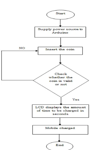
IV. FLOW CHART
V. HARDWARE IMPLEMENTATION
POWER SUPPLY: The Power Supply is a Primary requirement for the project work. The required DC power supply for the base unit as well as for the recharging unit is derived from the mains line. For this purpose center tapped secondary of 12V-012V transformer is used. From this transformer we getting 5V power supply. In this +5V output is a regulated output and it is designed using 7805 positive voltage regulator.
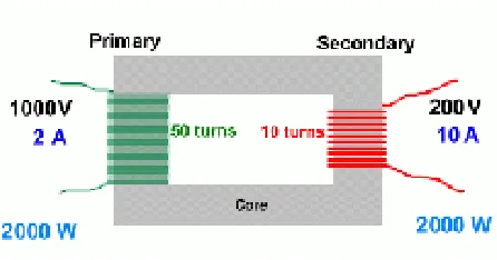
TRANSFORMER: Transformer is a device that converts the one form energy to another form of energy like a transducer. A transformer makes use of Faraday's law and the ferromagnetic properties of an iron core to efficiently raise or lower AC voltages. It of course cannot increase power so that if the voltage is raised, the current is proportionally lowered and vice versa. For this project we use step down transformer
Step down transformers are designed to reduce electrical voltage. Their primary voltage is greater than their secondary voltage. This kind of transformer "steps down" the voltage applied to it. For instance, a step down transformer is needed to use 110v product in a country with a 220v supply.
Figure 4.1: Step-Down Transformer
RELAY: A relay is an electrically operating switch. Current flowing through the coil of the relay creates a magnetic field which attracts a lever and changes the switch contacts. The coil current can be ON or OFF so relays have two switch positions and they are double through (changeover) switches.
LIQUID CRYSTAL DISPLAY: Liquid crystal displays (LCDs) have materials, which combine the properties of both liquids and crystals. LCD consists of two glass panels, with the liquid crystal material sand witched in between them.
IR SENSOR: An Infrared sensor(IR sensor) is an electronic device that measures infrared (IR) light radiating from objects in its field of view. Infrared transmitter is one type of LED which emits infrared rays generally called as IR Transmitter. Similarly IR Receiver is used to receive the IR rays transmitted by the IR transmitter. One important point is both IR transmitter and receiver should be placed straight line to each other.
Figure 4.2: Arduino Uno board
The Arduino Uno is a microcontroller board based on the ATmega328 It has 14 digital input/output pins (of which 6 can be used as PWM outputs), 6 analog inputs, a 16 MHz ceramic resonator, a USB connection, a power jack, an ICSP header, and a reset button. It contains everything needed to support the microcontroller; simply connect it to a computer with a USB cable or power it with an AC-to-DC adapter or battery to get started. The Uno differs from all preceding boards in that it does not use the FTDI USB-to-serial driver chip.
ATMEGA328/P: The Atmel Pico Power ATmega328/P is a low-power CMOS 8-bit microcontroller based on the AVR® enhanced RISC architecture. By executing powerful instructions in a single clock cycle, the ATmega328/P achieves throughputs close to 1MIPS per Mhz. This empowers system designer to optimize the device for power consumption versus processing speed [5].
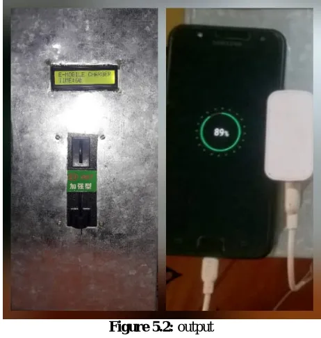
VI. EXPERIMENTAL RESULTS
Figure 5.2: output
VII. CONCLUSION
The coin based mobile phone charger is very useful to public for using coin to charge for the mobile phone in any public places just like charging it normally owing to the fact that it relayed the electricity through the coin based mobile charger needed to bring the mobile phone back to life. A novel method of charging mobile batteries of different manufactures using solar power has been designed and developed for rural and remote areas where the grid power is not available at any time at any place.
VIII. FUTURE ENHANCEMENT
The paper can be used in the following areas:-
Railway station: This type of project is used in railway station for public palace. Shop: coin based project charger can be installed at any shop to earn money.
Rural areas: This project can be installed in rural areas where the power grid is not available at any time. Public Place: This project is very useful when mobile phone battery dies in public places.
REFERENCES
[1] S .Banu Prathap, R.Priyanka, G.Guna,Dr.Sujatha “ coin based cell phone charger ” International Journal of Engineering Research & Technology(IJERT) ISSN:2278-0181 Volume 2,Issue 3 (March 2013).
[2] IOSR Journal of Engineering (IOSRJEN) ISSN: 2250-3021 Volume 2, Issue 6 (June 2012), PP 1433-1438.
[3] Pulvirenti, F. Milazzo, P. Ursino, R, Charger power switch for mobile phones, Analog and Mixed IC Design,. 1997. Proceedings 1997 2nd
IEEE-CAS Region 8. Workshop, 12-13 Sep 1997, Pg 97 - 100.
[4] Pastre, M. Krummenacher, F. Robortella, R. Simon-Vermot, R. Kayal, M. Ecole Polytech.
[5] Fed. De Lausanne, Lausanne, A fully integrated solar battery charger Circuits and Systems and TAISA Conference, 2009. NEWCAS-TAISA '09. Joint IEEE North-East Workshop.