Copyright to IJIRSET www.ijirset.com
3170
Stress Analysis for Wing Attachment Bracket
of a six seater Transport Airframe Structure
Harish E.R.M
1, Mahesha.K
2, Sartaj Patel
3P G student, Department of Mechanical Engineering, Acharya Institute of Technology, Bangalore, Karnataka, India1 Professor and Head, Department of Mechanical Engineering, Acharya Institute of Technology, Bangalore, Karnataka
India2
P G student, Department of Mechanical Engineering, Acharya Institute of Technology, Bangalore, Karnataka, India3
Abstract:In Current study the stress analysis of wing-fuselage attachment bracket is considered. It is necessary to ensure the static load carrying capability of the wing-fuselage attachment bracket. Stress analysis will be carried out for the given geometry of the wing-fuselage attachment bracket of a six seater transport airframe structure. Finite element method is used for the stress analysis.
Rarely an aircraft will fail due to a static overload during its service life. For the continued airworthiness of an aircraft during its entire economic service life, fatigue and damage tolerance design, analysis, testing and service experience correlation play a pivotal role.
Stress analysis helps in prediction of fatigue life of structural component of airframe structure.
Key words: Six Seater Transport airframe, Finite element method, bending moment, wing fuselage attachment bracket. I.INTRODUCTION
Lugs are connector type elements widely used as structural supports for pin connections in airframe structure. For ex. For attaching engines to engines pylon support fittings, wing fuselage attachment, and landing gear links are some of the typical applications can be found.
Failure of lug joints may lead to the catastrophic failure of the whole structure. Finite element analysis studies and experimental data help the designer to safeguard the structure from catastrophic failure.Attachment lugs can be some of the most fracture critical components in aircraft structure, and the consequences of structural lug failure can be very severe that sometimes the wing and fuselage get separated and result in accidents. Therefore, it is important to establish design criteria and analysis methods to ensure the damage tolerance of aircraft lug attachment.
II. GEOMETRICAL CONFIGURATION
Copyright to IJIRSET www.ijirset.com
3171 The wing fuselage attachment bracket considered for the study is shown in figure 2.1. The attachment bracket consists of a lug and a portion of the spar connected to each other by several bolts. The lug consists of two pin holes along with an integrated top flange and bottom flange which will be connected to the spar. The geometric dimensions of the lug attachment bracket are shown in the figure. Three views of wing fuselage lug attachment bracket are shown in the Figure 2.1. A three dimensional view of the lug attachment bracket is shown in the figure2.2.
Fig.2.2: A 3D view of wing attachment bracket
III. MATERIAL SPECIFICATION
In this current study,
The material considered for the lug attachment bracket of the structure is steel alloy AISI-4340, the following properties.
1. Young’s Modulus, E = 201105N/mm2 2. Poison's Ratio, μ = 0.3
3. Ultimate Strength, бu = 1530N/mm2
IV. LOADS ON THE WING FUSELAGE ATTACHMENT BRACKET
In an aircraft the spars carry’s the most of the bending. The maximum bending moment will be at the root of the spar where wing and fuselage components will be attached to each other.
A:Load calculation for the wing fuselage lug attachment bracket.
1) Aircraft category= six seater transport aircraft 2) Total weight of the aircraft=2500kg = 24525 N 3) Load factor considered in design=3g
4) Design limit load on the structure=3*24525=73575 N 5) Design ultimate load=73575*1.5=110362.5 N
6)The % of lift load acting on the wing is 80% =110362.5 * 0.8 = 88290 N 7) Load acting on the each wing= 88290/2=44145 N
8) Span wise distance of the resultant load from the root of the wing = 1400 mm 9) Total bending moment at the root = 44145*1400 = 61803000 N-mm.
Copyright to IJIRSET www.ijirset.com
3172 Front attachment = 55%
Rear attachment = 45%
12) Load at front attachment =83857 * 0.55 = 4621.64 N.
V. FINITE ELEMENT ANALYSIS
The finite element method (FEM) is a numerical technique for solving problems which are described by partial differential equations or can be formulated as functional minimization. A domain of interest is represented as an assembly of finite elements. Approximating functions in finite elements are determined in terms of nodal values of a physical field which is sought. A continuous physical problem is transformed into a discretized finite element problem with unknown nodal values. For a linear problem, a system of linear algebraic equations should be solved. Values inside finite elements can be recovered using nodal values.
The software used for the analysis of the wing fuselage attachment bracket of a six seater airframe structureis MSC.Patran & MSC. Nastran.
VI.FINITE ELEMENT MODEL OF THE WING FUSELAGE LUG ATTACHMENT BRACKET
A finite element model is the complete idealization of the entire structural problem including the node location, the element, physical and material properties, loads and boundary conditions. The purpose the finite element model is to make a model that behaves mathematically as being modelled and creates appropriate input files for the different finite element solvers.In Finite Elements libraries, selected 4 Nodded QUADRILATERAL Shell Element (QUAD4). In this Geometrical model for available surface area, chosen for formulation of FE Model, reason was flow of displacement and stiffness.
Fig.6.1 Three Noded TRIA Shell Element And 4Noded Quadrilateral Shell element.
FE model of the wing fuselage Lug attachment bracket is as shown in figure 6.1 Meshing is carried out by using CQUAD4 and CTRIA3 shell elements. Triangular elements are used for the transition between the coarser mesh to finer mesh.
Copyright to IJIRSET www.ijirset.com
3173 A:Different structural members of the wing fuselage Lug attachment bracket are
Lug
I-spar
Top and bottom flanges of the lug attachment bracket
Rivets
The corresponding mesh generated for each of the above mentioned members are shown in the figure below.
Fig.6.3 Finite Element (FE) model of the Lug.
Copyright to IJIRSET www.ijirset.com
3174 Fig.6.5 Finite Element (FE) model of the variable thickness plate.
Fig.6.6 FEA model of the Rivets(3D display form)
VII.LOADS AND BOUNDARY CONDITIONS
The loads and boundary conditions along with the finite element model are shown in the figure 7.1. A load 46121.64 N (i.e., 86.32 N/mm) of is introduced at one end of the spar beam. This load will essentially create the required bending moment at the root.
The top and bottom lug holes of the wing fuselage Lug attachment bracket are constrained with all six degrees of freedom at the semicircular circumferential region.
Fig.7.1 Load and Boundary conditions applied to the wing fuselageLug attachment bracket.
VIII.FINITE ELEMENT MODELLING AND STRESS ANALYSIS IN WING FUSELAGE ATTACHMENT BRACKET.
Copyright to IJIRSET www.ijirset.com
3175 A maximum displacement of 3.06 mm at the free end of the cantilever structure can be observed from the displacement contour in the figure 8.4.
Fig 8.1 Figure Showing Maximum Stresses of Wing Fuselage Lug
Attachment Bracket
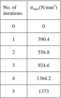
Table I convergence requirements
No. of iterations
σmax(N/mm2)
0 0
1 390.4
2 556.8
3 924.6
4 1364.2
5 1373
Copyright to IJIRSET www.ijirset.com
3176 Fig.8.2 Stress contour at the spar plate. Fig 8.3: close up view of the stress contour at the rivet hole of the
I-spar plate.
Fig.8.4 Displacement Contour of wing fuselage Lug attachment Bracket.
VIII. RESULTS AND DISCUSSIONS
The stress contour indicates a maximum stress of 1373 N/mm2 at one of the rivet hole of the I-spar.
The maximum stress value obtained is within the yield strength of the material. The point of maximum stress is the possible location of crack initiation in the structure due to fatigue loading.
IX. CONCLUSIONS
Stress analysis of the wing fuselage lug attachment bracket is carried out and maximum tensile stress is identified at one of the rivet hole of I-spar plate.FEM approach is followed for the stress analysis of the wing fuselage lug attachment bracket.)A validation for FEM approach is carried out by considering a plate with a circular hole.Maximum tensile stress of 1373N/mm2 (i.e., 140 kg/mm2) is observed in the I-spar plate.Several iterations are carried out to obtain a mesh independent value for the maximum stress.A fatigue crack normally initiates from the location maximum tensile stress in the structure, further fatigue life estimation can be carried out to predict the life of the airframe component.
ACKNOWLEDGEMENT
Copyright to IJIRSET www.ijirset.com
3177 guidance and advice for the analytical work.addition the author would like to thank theto Dr. Mahesha.K. Professor and Head of the Department, Mechanical Engineering, Acharya Institute of Technology, Bangalore.
REFERENCES
[1] Dragi Stamenkovic, Katarina Maksimovic. Vera Nikolic, Ivana Vasovic, “Fatigue life estimation of notched structural components”. The state university of Novi Pazar, Serbia. Military technical institute, Serbia.
[2] Gianni Nicoletto, “Experimental characterization of cracks at straight attachment lugs”. Bologna, Italy.
[3] Slobodanka Boljanovic, Stevan Maksimovic, “Strength analysis of attachment lugs under cyclic loading”.VTI-Aeronautical institute, Rata resamovic, Serbia.
[4] J. Vogwell and J. M. Minguez,“Failure in lug joints and plates with holes”. School of Mechanical Engineering, University of Bath, Bath BA2 7AY, U.K., Facultad de Ciencias, Universidad Del Pais Vasco, Bilbao, Spain.
[5] R. Rigby and M. H. “Stress intensity factors for cracks at attachment lugs”. Aliabadi, British Aerospace, Filton, Bristol BS99 7AR, U.K., Wessex Institute of Technology, Ashurst Lodge, Ashurst, Southampton S040 7AA, U.K.
BIOGRAPHY
Mr. Harish E.R.M obtained his B.E Mechanical from BIET, Davangere, in 2011 and is a P G student (M Tech in Machine Design) at Acharya institute of Technology, Bangalore. He is a Member of American Society ofMechanicalEngineers (ASME).
Dr.Mahesha.K,ME., Ph.D, presently working as a Professor and Head of the Department, Mechanical Engineering, Acharya Institute of Technology, Bangalore. He holds Life Time Membership of Indian Society for Technical Education (LMISTE) and Material Research Society of India (MRSI). He has published several papers in International Journals. His research area is in advanced materials and Damping characteristics of materials.