Discrete Space Vector Modulation Algorithm Based
Vector Controlled Induction Motor Drive
Mr. B.Chinna sanjeevarayudu
EEE Department, VBIT, Ghatkesar, Telangana, India
Mr. Malle sai prasad reddy
EEE Department, Associate professor ,VBIT, Ghatkesar, Telangana, India
Abstract:This paper presents a discrete space vector
modulation (DSVM) algorithm based vector controlled induction motor drive for reduced torque and current ripples in steady state. The classical vector control algorithm gives good transient and steady state response. But, the complexity involved in the classical vector control is more due to the reference frame transformations. To reduce the complexity, later direct torque control hasbeen developed.But,itgiveslargesteadystateripple.Hence,to overcomethedrawbacksofvectoranddirecttorquecontrol algorithms, a simple and novel vector control algorithm is proposed in this paper. The proposed algorithm combines the principles of both control algorithms. The reference currents are calculated based on the vector control. Then, the current error signals will be generated by comparing the actual and reference currents. By using the current error signals, sector information and lookup table, a suitable voltage vector is selected in order to keep the current errors within the hysteresis bands as per the principle of direct torque control. In the proposed algorithm, a 5-level hysteresis controller is used forq-axis current and 2-level hysteresis controller is used for d-axis current. To validate the proposed lookup tables based vectorcontrolalgorithm,numericalsimulationstudieshave been carried out and compared. The results show the effectiveness of the proposedalgorithm.
Keywords:discretespacevectormodulation,lookuptable,
induction motor drive, vectorcontrol.
1. Introduction
The induction motors are becoming popular in adjustable speed drive applications due to their numerous advantages. In order to control the induction motor similar to that of a separately excited dc motor, the field oriented control (FOC) or vector control algorithm was developed in 1971 by Blaschke [1]. The discovery of FOC brought revitalization in the field of high performance ac drives. Later, so many developments were proposed for FOC as discussed in [2]-[4]. Though, the FOC gives good dynamic and steady state response, the complexity involved is more due to the reference frame transformations.
To reduce the complexity involved in vector control
algorithm, Takahashi proposed direct torque control (DTC) algorithm for induction motor drives [5]. The DTC is simple for the real time implementation and it directly regulates the both torque and flux. In the DTC, in order to maintain the magnitudes of torque and flux errors within the hysteresis bands, a suitable voltage vector is selected by using the outputs of hysteresis comparators and lookup table. A detailed comparison between FOC and DTC was given in [6]. Though, the DTC gives good transient performance, it gives large steady state ripples in torque, flux and current during the steady state operation.
The classical DTC uses only limited number of voltage vectors in each sector, which leads to more ripple in steady state. Hence, to reduce the steady state ripple, a 12-sector based DTC was proposed in [7]. For the reduction of ripple further, a discrete space vector modulation (DSVM) algorithm has been proposed for DTC in [8]-[9]. The DSVM technique uses three voltage vectors in each sampling time interval. To reduce the complexity involved in the current controlled algorithms, a simple and novel lookup table based approach has been developed in[10].
To overcome the demerits of both FOC and DTC, the proposed algorithm combines the principles of both DTC and FOC. In the proposed vector control algorithm, the d-axis and q-axis reference currents are generated based on the principles of vector control. Then, by comparing the actual and reference currents, current error signals are generated. In order to reduce the steady state ripple, the proposed vector control algorithm uses DSVM technique. In the DSVM algorithm, a 5-level hysteresis controller is used for q- axis current loop and a 2-level hysteresis comparator is used for d-axis current loop. Based on the outputs of hysteresis comparators, speed and sector information, the DSVM algorithm selects a suitable voltage vector in order to maintain the errors within the specified limits.
2. Proposed VectorControl
m m
L
Te sin (1) Decoupled control can be achieved by acting on ids and
iqs components of the stator current vector. The
where is the angle between r and is . From (1), it movement of stator current vector can be represented
can be concluded that the Te can be changed by
changing the . Hence, fast torque control can be achieved by changing in the required direction. As the rotor inertia is more, the rotor flux is almost constant for a short time interval. Hence, the torque can be controlled by varying the stator current vector ( is )
in the required direction, according to the reference torque. By ignoring the stator resistance drop, the stator voltagecanbeexpressedasgivenin(2).
d
as shown in Fig. 1. This is the basic principle of proposed vector control technique.
Movement with active forward vector
Stops with zero vectors
Movement with active
vs s
dt
(2) is backwardvector
The stator flux linkage vector of an induction motor can be expressed as in(3)
2
r
Rotatescontinuously
s Lsis
L L
r
isr Lr
(3)
For short time interval, by assuming the r as constant,
the stator voltage expression can be simplified as follows:
Fig. 1 movement of stator current vector under the influence of voltage vectors
d L2 di di The block diagram for the proposed vector control
vs s Ls m s Ls s (4)
dt Lrdt dt
where σ is the leakage coefficient of induction motor. For a short time interval of t , the stator current vector can be obtained from (4) as
1
algorithm is as shown in Fig. 2. The reference currents, which are at synchronously rotating reference frame, are generated by using the principle of classical vector control. Then, by comparing the reference currents and actual currents, the current error signals are generated. is
Ls
vs t (5) These error signals are the inputs to the two hysteresis
comparators. Based on the digitized outputs that are Thus, the stator current vector moves by is in the
direction of the stator voltage vector at a speed proportional to magnitude of voltage vector. By selecting a suitable voltage vector it is then possible to change the stator current in the required manner.
generated from hysteresis comparators and sector information, suitable voltage vector is selected from the lookup table so as to keep the current error signals within the specified limits.
Fig. 2 Block diagram of proposed vector controlled induction motor drive Sector
, ids and
Vd
wr Te q
w
r id
S
q
iq MotorSig
I id
iqs QH Optim
al
ids DH
3 P Lm 2 2 Lr
ids
33Z 23Z 22Z
3ZZ 2ZZ
Sector 1+
ZZZ
q-axis Sector 1
-5ZZ 6ZZ
55Z 56Z 66Z
ds
qs
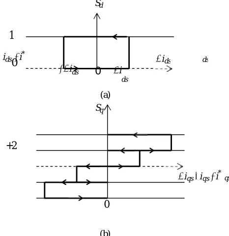
3.ProposedDiscreteSpaceVectorModulation The classical vector control algorithm gives more harmonic distortion and also more complex for real time implementation. To reduce the complexity and harmonic distortion the discrete space vector modulation (DSVM) technique is proposed for the proposed vector control. The proposed DSVM [8]-[9] uses a two-level hysteresis controller for d-axis current loop (DHC) similar to that of classical DTC algorithm and five-level hysteresis comparator for q-axis current loop. The DSVM technique uses a standard voltage source inverter and synthesizes a higher number of voltage vectors than those used in classical DTC algorithm. In the DSVM technique, each sampling time interval is divided into ‘k’ equal time intervals and any one of the voltage vector is applied in each sub- interval. The number of voltage vectors that produced is directly proportional to ‘k’. if the number of sub- intervals is more, then the complexity involved in constructing the switching table is also more. A good compromise between the errors compensation and the complexity of the switching tables is achieved by choosing k=3 [8]. By using the DSVM algorithm, with
k=3,atotalof36synthesizednon-zerovoltagevectors
voltage vectors in sector-1. As a consequence, the use of the DSVM technique improves the drive performance in terms of torque, flux and current ripple, with an increase of the inverter switching frequency. Moreover, in the DSVM technique, the voltage vector selection depends on the operating speed also. When the rotor speed is greater than one half of the synchronous speed, it belongs to the high-speed range. When the rotor speed is in between half of the synchronous speed and one sixth of the synchronous speed, it belongs to the medium speed range and when the rotor speed is lower than one sixth of the synchronous speed, it belongs to the low speed range. The DSVM algorithm uses a 2-level d-axis hysteresis current controller (DHC) and 5-level q-axis hysteresis current controller (QHC), which are described in Fig.4.
Sd
1
ids i*
0
i ds
0
i can be generated. If is is assumed to be in thefirst dssector, then 19 voltage vectors can be used, as represented in Fig. 3. The black dots represent the ends of the synthesized voltage vectors. As an example, the label “23Z” denotes the voltage vector which is synthesized by using the voltage space vectors V2, V3
andVZ,eachoneappliedforonethirdofthesampling
+2
period.+1
333 332 223 222
0
-1
-2
(a) Sq
(b)
iqs iqs i*
Fig. 4 (a) d-axis current controller (b) q-axis current controller
The output of the DHC, Sd , has two levels. Sd 0 means that the amplitude of ids should be reduced and
Sd 1 means that the amplitude of ids should be
increased. The output of the torque hysteresis controller, Sq , has five levels. When Sq 1 or 1, the
iqs needs limited or small variation and these levels
will be involved in steady state operating conditions.
When Sq 2 or 2 , the iqs is far away from its
555 556 665 666 reference value and needs a large, rapid change and these levels will be involved during high dynamic
Fig. 3 Synthesized voltage vectors obtained by using DSVM algorithm
The advantage of using the DSVM algorithm is that onecanselectasuitablevoltagevectoramong19
transients. When Sd 0 , the iqs is equal or close to its
reference value and should keep its value unchanged. Thus, based upon the outputs of the QHC, DHC and operating speed range, a suitable synthesized voltage
vector will be selected from the lookup table given in Table 1.
Table 1 Optimal switching table for DSVM algorithm (stator flux in sector 1)
Speed range
Sd Sq
-2 -1 0 +1 +2
Low 0 555 5ZZ ZZZ 3ZZ 333
1 666 6ZZ ZZZ 2ZZ 222
Middle 0 555 ZZZ 3ZZ 33Z 333
1 666 ZZZ 2ZZ 22Z 222
High sector 1+
0 555 3ZZ 33Z 333 333
1 666 2ZZ 23Z 223 222
High sector 1-
0 555 3ZZ 23Z 332 333
1 666 2ZZ 22Z 222 222
4. Simulation Results andDiscussion
To confirm the effectiveness of the proposed DSVM technique based vector controlled induction motor drive, simulation studies have been carried out and results are presented. For the numerical simulation studies the induction motor parameters are taken as Rs=1.57Ω, Rr=1.21Ω, Lm=0.165H, Ls=0.17H, Lr=0.17H and J=0.089Kg-m
2
. The simulation results of conventional vector controlled induction motor drive are shown in Fig.5-Fig.10. The simulation results of proposed DSVM based vector controlled induction motor drive are shown from Fig. 11 to Fig. 16. From the simulation results, it can be concluded that the proposed DSVM based vector control algorithm gives fast transient response like conventional vector control algorithm. From the steady state simulation results and harmonic spectra of line currents, it can be concluded that the proposed DSVM based vector control algorithm gives reduced harmonic distortion when compared with the conventional vector control algorithm.
Fig. 5 starting transients of classical vector control algorithm based induction motor drive
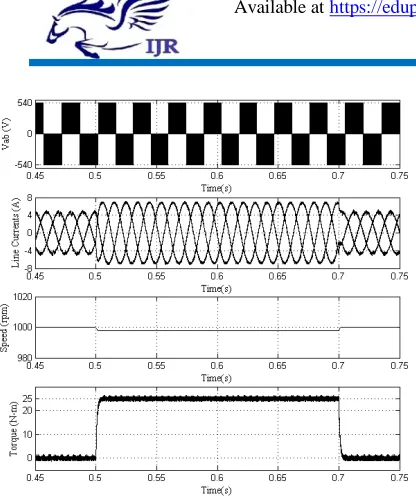
Fig. 6 steady state plots of classical vector control algorithm based induction motor drive
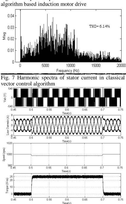
Fig. 7 Harmonic spectra of stator current in classical vector control algorithm
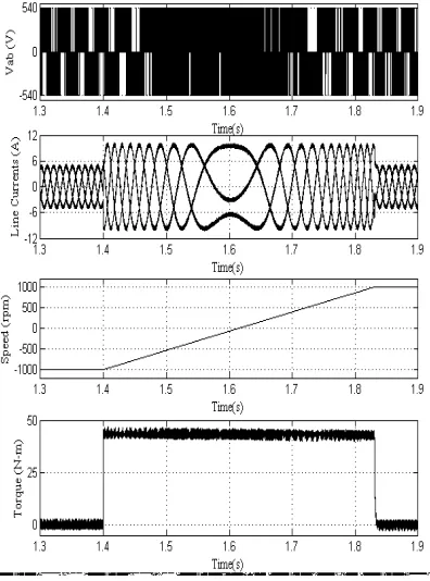
Fig. 9 Transients during the speed reversal (from
+1000 rpm to -1000 rpm) for classical vector control algorithm based induction motor drive
Fig. 10 Transients during the speed reversal (from - 1000 rpm to +1000 rpm) for classical vector control algorithm based induction motor drive
Fig. 11 starting transients of DSVM algorithm based vector controlled induction motor drive
Fig. 12 steady state plots of DSVM algorithm based vector controlled induction motor drive
Fig. 13 Harmonic spectra of stator current in DSVM algorithm based vector controlled induction motor drive
Fig. 14 Transients during the step change in load (a 25 N-m load is applied at 0.5 sec and removed at 0.7 sec) for DSVM algorithm based vector controlled induction motor drive
Fig. 15 Transients during the speed reversal (from
Fig. 16 Transients during the speed reversal (from - 1000 rpm to +1000 rpm) for DSVM algorithm based vector controlled induction motor drive
5. Conclusions
The vector controlled induction motor drives are popular in high performance variable speed drive applications. In order to reduce the complexity involved in the classical vector control algorithm, a simple lookup table based vector control algorithm is presented in this paper. Moreover, to reduce the harmonic distortion a DSVM based vector control algorithm is presented. To show the effectiveness of the proposed DSVM based vector control algorithm, several simulation results are presented and compared. From the simulation results, it can be observed that the proposed DSVM based vector control technique gives good transient response with reduced harmonic distortion and complexity when compared with the classicalvectorcontrolalgorithm
References
1. F. Blaschke “The principle of field orientation as applied to the new transvector closed loop control system for rotating-field machines," Siemens Review, 1972, pp217-220.
2. W. Leonhard, “30 years of space vectors, 20 years of field orientation, 10 years of digital signal processing with controlled AC-drives, a review (Part1)". EPE Journal, No. 1, July 1991, pages13-20.
3. W. Leonhard, “30 years of space vectors, 20 years of field orientation, 10 years of digital signal processing with controlled AC-drives, a review (Part 2)". EPE Journal, No. 2, Oct, 1991, pages89-102.
4. J. A. Santisteban, and R. M. Stephan, “Vector control methods for induction machines: an overview,” IEEE Trans.OnEducation,vol.44,no.2,pp.170-175,May
6
2001.
5. Isao Takahashi, Toshihiko Noguchi, “A new quick response and high-efficiency control strategy of an
induction motor”, IEEE Trans Ind Appl, Vol.IA-22, No.5, pp. 820-827, Sep/Oct,1986.
7. Y.V.SivaReddy,M.VijayakumarandT.Brahmananda Reddy, “Direct Torque Control of Induction Motor Using Sophisticated Lookup Tables Based on Neural Networks”AIMLJournal,Volume(7),Issue(1),June, 2007, pp.9-15.
8. D.Casadei,G.SerraandA.Tani,“Implementationofa direct torque control algorithm for induction motors based on discrete space vector modulation” IEEE Trans.PowerElectron.,vol.15,no.4,Jul2000,pp.769- 777.
9. Xin Wei, Dayue Chen and Chunyu Zhao, “Minimization of torque ripple of direct torque controlled induction machines by improved discrete space vector modulation” Journal of Electric Power Systems Research, 72, 2004, pp.103-112.
10. Marian P. Kaimierkowski, Maciej A. Dzieniakowski, andWaldemarSulkowski,“NovelSpaceVectorBased current controllers for PWM-inverters” IEEE Trans. PowerElectronics,vol.6,no.1,Jan,1991,pp.158-166.
Mr. B.Chinna sanjeevarayudu M.Tech (power electronics and electrical drives)pursuingin vignana bharati institute of technology,aushapur(vi),ghatkesar(dist)
501301,Telangana state ,india email id: [email protected]
Mr. Malle sai prasad reddy was born in india .he received b.tech passedout in 2004 & M.Tech passedout in 2006.he is expert in controlsystems, electrical measurements machines, power electronics ,electrical circuts subjects. he is currently working as an associate professor in eee
department in vignana
bharathiinstituteoftechnology,aushapur