Tightening Threshold Implementations
Pascal Sasdrich, Amir Moradi, Tim G¨uneysu
Horst G¨ortz Institute for IT Security, Ruhr-Universit¨at Bochum, Germany {pascal.sasdrich, amir.moradi, tim.gueneysu}@rub.de
Abstract. Motivated by the development of Side-Channel Analysis (SCA) countermeasures which can provide security up to a certain order, de-feating higher-order attacks has become amongst the most challenging issues. For instance, Threshold Implementation (TI) which nicely solves the problem of glitches in masked hardware designs is able to avoid first-order leakages. Hence, its extension to higher first-orders aims at counter-acting SCA attacks at higher orders, that might be limited to univariate scenarios. Although with respect to the number of traces as well as sensi-tivity to noise the higher the order, the harder it is to mount the attack, ad-order TI design is vulnerable to an attack at orderd+ 1.
In this work we look at the feasibility of higher-order attacks on first-order TI from another perspective. Instead of increasing the first-order of re-sistance by employing higher-order TIs, we go toward introducing struc-tured randomness into the implementation. Our construction, which is a combination of masking and hiding, is dedicated to TI designs and deals with the concept of “affine equivalence” of Boolean functions. Such a combination hardens a design practically against higher-order attacks so that these attacks cannot be successfully mounted. We show that the area overhead of our construction is paid off by its ability to avoid higher-order leakages to be practically exploitable.
1
Introduction
for the first-order, 5 shares for the second-order, and at least 7 shares for the third-order security.
Contribution: In this work we look at the feasibility of higher-order attacks on first-order secure TI designs from another perspective. Instead of increasing the resistance against higher-order attacks by employing higher-order TIs, we intend to introduce structured randomness into a first-order secure TI. Our goal is to practically harden designs against higher-order attacks that are known to be sensitive to noise.
Concretely, we investigate the PRESENT [7] S-box under first-order secure TI settings that is decomposed into two quadratic functions thereby allowing the minimum number of three shares. By changing the decompositions during the operation of the device we can introduce (extra) randomness to the implemen-tation. In particular we present different approaches to find and generate these decompositions on an FPGA platform and compare them in terms of area and time overheads. More importantly, we examine and compare the practical eval-uation results of our constructions using a state-of-the-art leakage assessment methodology [10] at higher orders.
Our proposed approach which can be considered as a hiding technique is combined with first-order TI which provides provably secure first-order resis-tance. Therefore, although such a combination leads to higher area overhead, it brings its own advantage, i.e., practically avoiding the feasibility of higher-order attacks.
Outline: The remainder of this article is organized as follows: Section 2 recapit-ulates the concept of TI. We also briefly introduce the S-box decomposition for TI and affine equivalence in case of the PRESENT S-box. In Section 3 different approaches to find and exchange affine equivalent functions are presented and compared. Practical evaluation of our construction is given in Section 4. Finally, we conclude our research in Section 5.
2
Background
2.1 Threshold Implementation
We use lower-case letters for single-bit random variables, bold ones for vectors, raising indices for shares, and lowering indices for elements within a vector. We represent functions with sans serif fonts, and sets with calligraphic ones.
Let us denote an intermediate value of a cipher byx made of s single-bit signalshx1, . . . , xsi. The underlying concept of Threshold Implementation (TI) is
to use Boolean masking to representxin a shared form (x1, . . . ,xn), wherex= n
L i=1
xi and eachxi similarly denotes a vector ofssingle-bit signals hxi
n L i=1
L(xi). However, the realization of non-linear functions, e.g., an S-box, over
Boolean masked data is challenging. Following the concept of TI, if the algebraic degree of the underlying S-box is denoted byt, the minimum number of shares to realize the S-box under the first-order TI settings isn=t+ 1. Further, such a TI S-box provides the output y =S(x) in a shared form (y1, . . . ,ym) with m≥nshares (usuallym=n) in case of Bijective S-boxes. In case of a bijective S-box (e.g., of PRESENT) the bit length ofxandy(respectively of their shared forms) are the same.
Each output shareyj∈{1,...,m} is given by a component functionfj(.) over a subset of the input shares. To achieve the first-order security, each component functions fj∈{1,...,m}(.) must be independent of at least one input share.
Since the security of masking schemes is based on the uniform distribution of the masks, the output of a TI S-box must be also uniform as it is used as input in further parts of the implementation (e.g., the SLayer output of one PRESENT cipher round which is given to the next SLayer round after being processed by the linear PLayer and key addition). To express the uniformity under the TI concept suppose that for a certain input x all possible sharings
X = n(x1, . . . ,xn)|x = Ln i=1
xio are given to a TI S-box. The set made by
the output shares, i.e., n f1(.), . . . ,fm(.)
|(x1, . . . ,xn) ∈ Xo, should be drawn
uniformly from the setY =n(y1, . . . ,ym)|y= Lm i=1
yio as all possible sharings
ofy=S(x).
This process so-called uniformity check should be individually performed for
∀ x∈ {0,1}s. We should note that if an S-box is a bijection andm =n, each (x1, . . . ,xn) should be mapped to a unique (y1, . . . ,yn). In other words, in this case it is enough to check whether the TI S-box forms also a bijection with s·n input (and output) bit length. For more detailed information we refer the interested reader to the original article [15].
2.2 S-Box Decomposition
before, the target of this work is an implementation of PRESENT cipher, which involves a 4×4 invertible cubic S-box (i.e., with the algebraic degree of 3) with Truth Table C56B90AD3EF84712. Therefore, all the representations below are coordinated based on 4-bit bijections.
In [16], where the first TI of PRESENT is presented, the authors gave a decomposition of the PRESENT S-box by two quadratic functions, i.e., each of which with the algebraic degree of 2. Later the authors of [4] and [5] presented a systematic approach which allows deriving the TI of all 4-bit bijections. In their seminal work they provided 302 classes of 4-bit bijections, with the application that every 4-bit bijection is affine equivalent to only one of such 302 classes. Based on their classification, the PRESENT S-box belongs to the cubic class
C4
266with Truth Table0123468A5BCFED97. It other words, it is possible to write
the PRESENT S-box asS:A0◦ C4
266◦A, whereA0(.) andA(.) are 4-bit bijective
affine functions. Therefore, given the uniform TI representation of C4
266 one can
easily applyA(.) on all input shares and A0(.) on all output shares to obtain a uniform TI of the PRESENT S-box.
As stated in [5]C4
266 can be decomposed into two 4-bit quadratic bijections
belonging to the following combinations of classes: (Q12◦ Q12), (Q293◦ Q300),
(Q294◦ Q299), (Q299◦ Q294), (Q299◦ Q299), (Q300◦ Q293), and (Q300◦ Q300).
However, the uniform TI of the quadratic class Q300 with 3 shares can only
be achieved if it is again decomposed in two parts. Therefore, the above de-compositions in which Q300 is involved need to be implemented in 3 stages if
the minimum number of 3 shares is desired. Excluding such decompositions we have four options to decompose the PRESENT S-box in two stages with 3-share uniform TI since the PRESENT S-box is affine equivalent to C4
266.
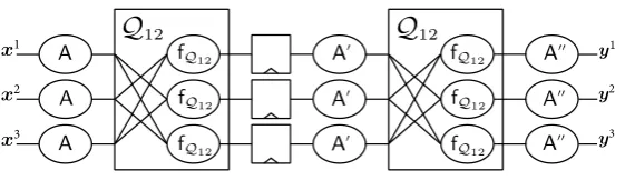
For the sake of simplicity – as an example – we consider the first decompo-sition, i.e.,Q12◦ Q12, which indicates that it is possible to write the PRESENT
S-box asS:A00◦ Q
12◦A0◦ Q12◦A, where all threeA00(.),A0(.), andA(.) are 4-bit
affine bijections. Thanks to the classifications given in [5] a uniform first-order TI ofQ12 can be achieved bydirect sharing. ForQ12:0123456789CDEFABwe can
write
e=a, f =b+bd+cd, g=c+bd, h=d, (1)
withha, b, c, dithe 4-bit input,he, f, g, hithe 4-bit output, andaandethe least significant bits.
The component functions of the uniform first-order TI ofQ12can be derived
byfQ12i,j (hai, bi, ci, dii,haj, bj, cj, dji) =he, f, g, hias
e=ai, f =bi+bjdj+cjdj+djbi+djci+bjdi+cjdi, g=ci+bjdj+djbi+bjdi, h=di. (2)
The three 4-bit output shares provided byfQ122,3(., .),fQ123,1(., .) andfQ121,2(., .) make a uniform first-order TI of Q12. Since the affine transformations (A,A0,A00) do
A
A
A
A0
A0
A0
A00
A00
A00
Q
12Q
12fQ12
fQ12
fQ12
fQ12
fQ12
fQ12
x1
x2
x3
y1
y2
y3
Fig. 1.A first-order TI of the PRESENT S-box
shows the graphical view of such a construction, and the detailed formulas of the component functions are given in Appendix A.
2.3 Affine Equivalence
In order to find such affine functions we give a pseudo code in Algorithm 1 which is mainly formed following [6]. The algorithm is based on precomputation of all 4×4 linear functions, i.e. 20 160 cases, each of which is represented by a 4×4 binary matrix with columns (c0,c1,c2,c3). Hence, each affine function A(.) is considered as a matrix multiplication followed by a constant addition
A(x) = [c0 c1c2 c3]·x⊕c.
Algorithm 1: Find affine equivalent triples Input :L4: all 4×4 linear permutations,
S: targeted S-box, F,G: targeted functions
Output: A: all (A,A0,A00) asS:A00◦G◦A0◦F◦A A ← ∅
for∀L∈ L4,∀c∈ {0,1}4 do
formaffineAbyLand constantc
for∀L0∈ L4, ∀c0∈ {0,1}4 do
formaffineA0 byL0 and constantc0 c00←G A0 F A S−1(0)
c001 ←G A0 F A S−1(1)
⊕c00 c002 ←G A0 F A S−1(2)
⊕c00 c003 ←G A0 F A S−1(4)
⊕c00 c004 ←G A0 F A S−1(8)
⊕c00
formaffineA00−1
by columns (c001,c002,c003,c004) and constantc00
if ∀y∈ {0,1}4\ {0,1,2,4,8}, G A0 F A S−1(y) ?
=A00−1
(y)then deriveaffineA00as the inverse ofA00−1
A ← A ∪
(A,A0,A00)
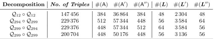
Table 1.The number of existing affine triples for different compositions
Decomposition No. of Triples #(A) #(A0) #(A00) #(L) #(L0) #(L00)
Q12◦ Q12 147 456 384 36 864 384 48 2 304 48
Q294◦ Q299 229 376 512 57 344 448 56 3 584 64
Q299◦ Q294 229 376 448 57 344 512 64 3 584 56
Q299◦ Q299 200 704 448 50 176 448 56 3 136 56
Given the PRESENT S-box and f = g = Q12 the algorithm finds 147 456
such 3-tuple affine bijections (A,A0,A00). Table 1 lists the number of found affine triples for each of the aforementioned decompositions.
3
Design Considerations
This section briefly demonstrates the architecture the PRESENT TI which we have implemented. Afterwards, different approaches for generating and exchang-ing affine triples are presented and compared.
3.1 Threshold Implementation of PRESENT cipher
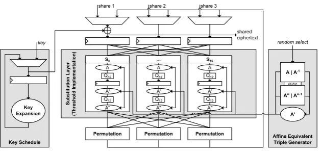
PRESENT is a lightweight symmetric block cipher with a block size of 64 bits and either 80-bit or 128-bit security level (i.e., key size). The encryption of a plaintext is based on a Substitution-Permutation (S/P) network always taking 31 rounds and 32 sub-keys to compute the ciphertext (independently of the security level). The only difference between PRESENT-80 and PRESENT-128 is in the key schedule function to derive the sub-keys from the initial 80-bit or 128-bit key. Figure 2 gives an overview of our hardware architecture implemented on an Xilinx Spartan-6 FPGA. We opted to implement the PRESENT encryption scheme in a round-based manner along with the 128-bit key schedule variant. The sub-keys are derived on-the-fly. The substitution layer uses the first-order TI of the PRESENT S-box shown in Figure 1 and implements 16 S-boxes in parallel before the permutation is applied bitwise to all 64-bit states. Due to the additional register stage within the TI S-box each round requires two clock cycles.
As stated in Section 2.3, given a certain decomposition there exist many triple affine functions to realize a uniform first-order TI of the PRESENT S-box. Our goal is to randomly change such affine functions on the fly, that it first does not affect the correct functionality of the S-box, and second randomizes the intermediate values – particularly the sharedQ12 inputs – with the aim of
KeyxSchedule
AffinexEquivalent TriplexGenerator
Subst
itution
xLayer
5Thresh
oldxImplementation
)
Keyx Expansion
Ax|xA-1
A..x|xA..-1 key
share 1 share 2 share 3
Permutation Permutation Permutation
BRAM random select
S0
A Q12
A' Q12
A''
... S15
A Q12
A' Q12
A''
A Q12
A' Q12
A''
A. shared
ciphertext
Fig. 2.Architecture of the PRESENT encryption design
affine triples randomly. Below we discuss about different ways to realize such a part of the design.
3.2 Searching for the Affine Triples
At a first step, we decided to implement Algorithm 1 as a hardware circuit which searches for the affine triples in parallel to the encryption. The found affine triples are stored into a “First In, First Out” (FIFO) memory, and prior to each encryption one affine triple is taken from the FIFO with which the corresponding part of the TI S-boxes are configured. If the FIFO is empty, the previous affine triple is used again. Due to the fact that the search is not time-invariant, i.e., new affine triples are not found periodically, some affines are used multiple times in a row while others are only used once. Since the efficiency of SCA countermeasures depends on the uniformity of the used randomness, such an implementation may not achieve the desired goal (i.e., hardening the higher-order attacks) if certain affines are used more often that the others. One solution to find affine triples more often is to run the search circuit with a higher clock frequency compared to that of the encryption circuit. Although this measure is limited, it at least alleviates the problem of changing S-boxes not periodically. On the other hand, if affine triples are found too fast this may cause a FIFO overflow. In this case either some search results should be ignored or the search circuit should be stopped requiring some additional control logic.
3.3 Selecting Precomputed Affine Triples
As stated in Table 1, considering the decompositionQ12◦Q12, there exist 147 456
offers only 3 Mbit storage in terms of general purpose block memory (BRAM). Therefore, alternative approaches to generate the affine equivalent triples are necessary.
Instead of storing the affines in a look-up table, in the second option we represent an exemplary affine A(x) = L·x⊕c, with xas a 4-bit vector, L a 4×4 binary matrix andca 4-bit constant. In this case, only the binary matrix and the constant need to be stored which reduces the memory requirements to 20 bits per affine. However, still more than 8 Mbit memory are necessary to store all affine triples. Therefore, we could store only a fraction of all possible affine triples. As an example, 16 384 affine triples occupy 60 BRAMs of the Spartan-6 (LX75) FPGA.
3.4 Generating Affine Triples On-the-fly
A detailed analysis of the affine triples led to interesting observations. First, the number of affine triples depends on the components in the underlying decompo-sition. For instance, in case ofQ299◦ Q299 448×448 and in case ofQ299◦ Q294
448×512 affine triples exist (see Table 1). Second, the total number of affine triples is limited by the number of unique input affines A and the number of output affinesA00 such that |A| × |A00| gives the number of corresponding affine triples. This means that all affine triples of a decomposition can be generated by combining allAwith allA00. Furthermore, we have observed that all affinesA (for each decomposition) consist of a few linear matrices combined with certain constants. In particular, in case of the decomposition Q12◦ Q12 the 384 input
affines A are formed by 48 binary matrices L each of which combined with 8 different constantsc∈ {0, . . . ,7} or c∈ {8, . . . ,15}. Indeed the same holds for the 384 output affines A00 which are made of 48 binary matrices L00 by con-stantsc∈ {0,1,4,5,10,11,14,15} orc∈ {2,3,6,7,8,9,12,13}. Therefore, it is sufficient to store only all relevant binary matrices L and L00 in addition to a single bit indicating to which group their constants belong to. Hence, in total 48×2×(16+1) = 1632 bits of memory (fitting into a single BRAM) are required to store all necessary data. Even better, by arranging the binary matrices in the memory smartly the group of the corresponding constants can be derived from the address where the binary matrix is stored.
Given two input and output affinesAand A00, we need to derive the middle affine A0. To this end, an approach similar to Algorithm 1 can be used. If we represent the middle affine asA0(x) =L0·x⊕c0, the constantcand the columns (c01,c02,c03,c04) of the binary matrixL can be derived as
c0=Q12−1 A00−1 S A−1 Q12−1(0) (3)
c01=Q12−1 A00−1 S A−1 Q12−1(1)⊕c0 (4)
c02=Q12−1 A00−1 S A−1 Q12−1(2)⊕c0 (5)
c03=Q12−1 A00−1 S A−1 Q12−1(4)⊕c0 (6)
Obviously, this requires the inverse of bothAandA00. Since it is not efficient to derive such inverse affines on the fly, we need to store all binary matricesL−1
and L00−1 in addition to all L and L00. Fortunately, all such binary matrices (requiring 3 kbits) still fit into a single 16-kbit BRAM of Spartan-6 FPGA. It is noteworthy that the constant of each inverse affine can be computed byL−1·c.
In summary, at the start of each encryption twoLandL00(each of which from a set of 48 cases) are randomly selected, that needs 6 + 6 bits of randomness1. In addition, 3 + 3 random bits are also required to form constants c and c00. As exampled before, one bit of each constant should be additionally saved or derived from the address of the binary matrix. Therefore – excluding the masks required to represent the plaintext in a 3-share form for the TI design – in total 18 bits randomness is required for each encryption.
For ASIC platforms, where block memories are not easily available, an alter-native is to derive the content of binary matricesLandL00as Boolean functions over the given random bits. Hence, a fully combinatorial circuit can provide the input and output affines followed (as before) by a module which retrieves the middle affine.
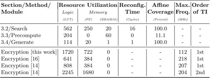
3.5 Comparison
Table 2 gives an overview of the design of the three above-mentioned approaches to derive the affine triples. The table reports the area overhead, reconfiguration time, and coverage of the affines’ space. Comparing the first naive approach (of searching the affine triples in parallel to the encryption) to the approach of pre-computing affine triples, the logic requirements could be dramatically decreased at cost of additional memory. In addition, the amount of affine triples that are covered is limited potentially reducing the security gain. We should note that the 20 BRAMs used in the “Search” approach are due to the space required to store all 4×4 linear permutations L4 required to run Algorithm 1 (excluding
those required for the FIFO). The last approach where the affine triples are generated on-the-fly seems to be the best choice. It not only leads to the least area overhead (both logic and memory requirements) but also covers the whole number of possible affine triples.
We should note that our design needs a single clock cycle to derive the middle affineA0. Indeed the 114 LUTs (reported in Table 2) are mainly due to realization of the Equations (3)-(7) in a fully combinatorial fashion.
Further, with respect to the design architecture of the encryption function (Figure 2) the quadratic component functions ofQ12are implemented by look-up
tables (LUTs), and the affine functions by fully combinatorial circuits realizing the binary matrix multiplication (AND operations) and XOR with the constant. Therefore, given (16+4) bits as the content of the binary matrix and the con-stant, the circuit does not need any extra clock cycles for configuration. Table 2 also gives an overview of the area and speed overhead of our design compared to a similar designs. For the first reference, the TI S-box is implemented by the
1
Table 2.Area and time overhead of different design approaches
Section/Method/ Resource Utilization Reconfig. Affine Max. Order Module Logic Memory Time Coverage Freq. of TI
(LUT) (FF) (BRAM16) (Cycles) (Percent) (MHz)
3.2/Search 562 250 20 16 100.0 -
-3.3/Precompute 204 0 60 0 11.1 -
-3.4/Generate 114 20 1 1 100.0 -
-Encryption [this work] 1720 722 0 - - 112 1st
Encryption [16] 641 384 0 - - 218 1st
Encryption [14] 808 384 0 - - 207 1st
Encryption [14] 2245 1680 0 - - 204 2nd
design of [16] (i.e., without any random affine). The second reference implements both a first-order and a second-order TI S-box for PRESENT in a similar fash-ion (usingQ294 andQ299 instead ofQ12) but with fixed affine transformations.
The numbers for the encryption function exclude the PRNG as well as the cir-cuit which finds/derives the affines. Due to the extra logic to support arbitrary affines, our design is certainly larger and slower.
4
Evaluation
We employed a SAKURA-G platform [1] equipped with a Spartan-6 FPGA for practical side-channel evaluations using the power consumption of the device. The power consumption traces have been measured and recorded by means of a digital oscilloscope with a 1 Ω resistor in the Vdd path and capturing at the embedded amplifier of the SAKURA-G board. We sampled the voltage drop at a rate of 500 MS/s and a bandwidth limit of 20 MHz while the design was running at a low clock frequency of 3 MHz to reduce the noise caused by overlapping of the power traces.
4.1 Non-Specific Statistical t-test
with a high level of confidence – the device under test does not exhibit any exploitable leakage.
4.2 Results
In this section we present the result of the side-channel evaluations concerning the efficiency of our introduced approaches to avoid higher-order leakages. In order to solely evaluate the influence of randomly exchanging the affine triples we considered a single design in our evaluations. As a reference, the design is kept running with a constant affine triple2, and its evaluation results are compared to the case where the affine triples are randomly changed prior to each encryption. Note that in both cases (constant affine and random affine) the PRNG which provides masks for the initial second-order masking (with three shares) is kept active. In other words, both designs – based on the TI concept – are expected to provide first-order resistance, and their difference should be in exhibiting higher-order leakages.
In Section 3 we introduced three different approaches to derive affine triples. Due to the issues and limitation of both first approaches, we have included the practical evaluation results of only the third option in Section 3.4, i.e., generating affine triples on-the-fly, which covers all possible affine triples.
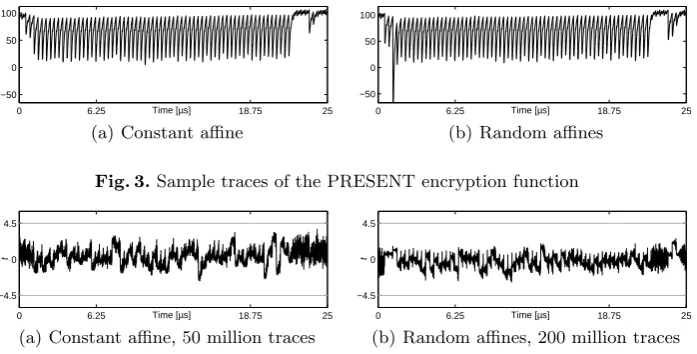
Figure 3 shows two sample traces corresponding to the cases where the affine triple is constant or random. The main difference between these two traces can be seen by a large power peak at the beginning of the trace belonging to the random affines. Such a peak indicates the corresponding clock cycle where the random affine is selected and the middle affine is computed (as stated in Section 3.5, it is implemented by a fully combinatorial circuit). The first-order, second-order and third-ordert-test results are shown in Figures 4-6 respectively for both constant and random affine. As expected, both designs do not exhibit any first-order leakage confirming the validity of our setup and designs. However, changing the affine triples randomly could avoid the second- and third-order leakage from being detectable. This can be seen in Figure 5 and Figure 6. We should highlight that the evaluations of the design with a constant affine have been performed by 50 million traces while we continued the measurements and evaluations of the design with random affines up to 200 million traces.
5
Discussions
The scheme, which we have introduced here to harden higher-order attacks, at the first glance seems to just add more randomness to the design. We should stress that our approach is not the same as the concept of remasking applied in [2, 5, 13]. Remasking (or mask refreshing) can be done e.g., by adding two new fresh random masksr1and r2 to the input of the TI S-box in Figure 1 as
(x1⊕r1,x2⊕r2,x3⊕r1⊕r2). Since our construction of the PRESENT TI S-box
2
0 6.25 18.75 25 −50
0 50 100
Time [µs] (a) Constant affine
0 6.25 18.75 25 −50
0 50 100
Time [µs] (b) Random affines
Fig. 3.Sample traces of the PRESENT encryption function
0 6.25 18.75 25 −4.5
0 4.5
Time [µs]
t
(a) Constant affine, 50 million traces
0 6.25 18.75 25 −4.5
0 4.5
Time [µs]
t
(b) Random affines, 200 million traces
Fig. 4.Non-specifict-test: first-order evaluation results
0 6.25 18.75 25 −21
0 21
Time [µs]
t
(a) Constant affine, 50 million traces
0 6.25 18.75 25 −4.5
0 4.5
Time [µs]
t
(b) Random affines, 200 million traces
Fig. 5.Non-specifict-test: second-order evaluation results
0 6.25 18.75 25 −14
0 14
Time [µs]
t
(a) Constant affine, 50 million traces
0 6.25 18.75 25 −4.5
0 4.5
Time [µs]
t
(b) Random affines, 200 million traces
Fig. 6.Non-specifict-test: 3rd-order evaluation results
fulfills the uniformity, such a remasking does not have any effect on the practical security of the design as both (x1,x2,x3) and (x1⊕r1,x2⊕r2,x3⊕r1⊕r2)
are 3-share representations of x. In contrast, in our approach e.g., the input affineArandomly changes. Hence the input of the firstQ12function is a 3-share
of S(x) and random affine triples do not affect the PLayer (of the PRESENT cipher), the key addition and the values stored in the state register, our approach is not expected to harden third-order attacks that target the leakage of these modules. However, our construction (which is a combination of masking and hiding) allows to achieve the presented efficiencies with low number of (extra) required randomness, i.e., 18 bits per encryption. Indeed, our approach might be seen as a form of shuffling which can be applied on the order of S-box executions in a serialized architecture. However, our construction is independent of the underlying architecture (serialized versus round-based) and allows hiding the exploitable higher-order leakages in a systematic way.
References
1. Side-channel AttacK User Reference Architecture. http://satoh.cs.uec.ac.jp/ SAKURA/index.html.
2. B. Bilgin, B. Gierlichs, S. Nikova, V. Nikov, and V. Rijmen. A More Efficient AES Threshold Implementation. InAFRICACRYPT 2014, volume 8469 ofLNCS, pages 267–284. Springer, 2014.
3. B. Bilgin, B. Gierlichs, S. Nikova, V. Nikov, and V. Rijmen. Higher-Order Thresh-old Implementations. InASIACRYPT 2014, volume 8874 ofLNCS, pages 326–343. Springer, 2014.
4. B. Bilgin, S. Nikova, V. Nikov, V. Rijmen, and G. St¨utz. Threshold Implementa-tions of All 3Ö3 and 4Ö4 S-Boxes. InCHES 2012, volume 7428 ofLNCS, pages 76–91. Springer, 2012.
5. B. Bilgin, S. Nikova, V. Nikov, V. Rijmen, N. Tokareva, and V. Vitkup. Threshold implementations of small S-boxes. Cryptography and Communications, 7(1):3–33, 2015.
6. A. Biryukov, C. D. Canni`ere, A. Braeken, and B. Preneel. A Toolbox for Cryptanal-ysis: Linear and Affine Equivalence Algorithms. InEUROCRYPT 2003, volume 2656 ofLNCS, pages 33–50. Springer, 2003.
7. A. Bogdanov, L. R. Knudsen, G. Leander, C. Paar, A. Poschmann, M. J. B. Rob-shaw, Y. Seurin, and C. Vikkelsoe. PRESENT: An Ultra-Lightweight Block Cipher. InCHES 2007, volume 4727 ofLNCS, pages 450–466. Springer, 2007.
8. S. Chari, C. S. Jutla, J. R. Rao, and P. Rohatgi. Towards Sound Approaches to Counteract Power-Analysis Attacks. In CRYPTO 1999, volume 1666 ofLNCS, pages 398–412. Springer, 1999.
9. T. Eisenbarth, T. Kasper, A. Moradi, C. Paar, M. Salmasizadeh, and M. T. M. Shalmani. On the Power of Power Analysis in the Real World: A Complete Break of the KeeLoq Code Hopping Scheme. InCRYPTO 2008, volume 5157 ofLNCS, pages 203–220. Springer, 2008.
10. G. Goodwill, B. Jun, J. Jaffe, and P. Rohatgi. A testing method-ology for side channel resistance validation. In NIST non-invasive attack testing workshop, 2011. http://csrc.nist.gov/news_events/ non-invasive-attack-testing-workshop/papers/08_Goodwill.pdf.
11. P. C. Kocher, J. Jaffe, and B. Jun. Differential Power Analysis. InCRYPTO 1999, volume 1666 ofLNCS, pages 388–397. Springer, 1999.
13. A. Moradi, A. Poschmann, S. Ling, C. Paar, and H. Wang. Pushing the Limits: A Very Compact and a Threshold Implementation of AES. InEUROCRYPT 2011, volume 6632 ofLNCS, pages 69–88. Springer, 2011.
14. A. Moradi and A. Wild. Assessment of hiding the higher-order leakages in hardware - what are the achievements versus overheads? To appear in the proceedings of CHES 2015, 2015.
15. S. Nikova, V. Rijmen, and M. Schl¨affer. Secure Hardware Implementation of Non-linear Functions in the Presence of Glitches. J. Cryptology, 24(2):292–321, 2011. 16. A. Poschmann, A. Moradi, K. Khoo, C. Lim, H. Wang, and S. Ling. Side-Channel
Resistant Crypto for Less than 2,300 GE. J. Cryptology, 24(2):322–345, 2011. 17. J. R. Rao, P. Rohatgi, H. Scherzer, and S. Tinguely. Partitioning Attacks: Or How
to Rapidly Clone Some GSM Cards. InIEEE Symposium on Security and Privacy 2002, pages 31–41. IEEE Computer Society, 2002.
18. O. Reparaz. A note on the security of Higher-Order Threshold Implementations. Cryptology ePrint Archive, Report 2015/001, 2015. http://eprint.iacr.org/. 19. T. Schneider and A. Moradi. Leakage Assessment Methodology - a clear roadmap
for side-channel evaluations. Cryptology ePrint Archive, Report 2015/207, 2015.
http://eprint.iacr.org/.
20. Y. Zhou, Y. Yu, F. Standaert, and J. Quisquater. On the Need of Physical Security for Small Embedded Devices: A Case Study with COMP128-1 Implementations in SIM Cards. InFinancial Cryptography 2013, volume 7859 ofLNCS, pages 230–238. Springer, 2013.
A
Necessary component functions for a first-order TI of
PRESENT S-box
y1=fQ122,3(ha2, b2, c2, d2i,ha3, b3, c3, d3i) =he, f, g, hi
e=a2, f =b2+b3d3+c3d3+d3b2+d3c2+b3d2+c3d2,
g=c2+b3d3+d3b2+b3d2, h=d2. (8)
y2=f3,1
Q12(ha3, b3, c3, d3i,ha1, b1, c1, d1i) =he, f, g, hi
e=a3, f =b3+b1d1+c1d1+d1b3+d1c3+b1d3+c1d3, g=c3+b1d1+d1b3+b1d3, h=d3. (9)
y3=fQ121,2(ha1, b1, c1, d1i,ha2, b2, c2, d2i) =he, f, g, hi