IJEDR1302003 INTERNATIONAL JOURNAL OF ENGINEERING DEVELOPMENT AND RESEARCH | IJEDR Website: www.ijedr.org | Email ID: [email protected] 12
Parametric study of An Innovative Approximate
Method of Continuous Beam
Dipak J.Varia
Research Scholar Rai University Ahmedabad, India [email protected]
Dr.Harshvadan S. Patel
Applied Mechanics Department Government Engineering college
Patan, India [email protected]
Abstract— Structure Engineers are using exact methods to analyze indeterminate structures. These methods produce a structural solutions that satisfies the equilibrium of forces and compatibility of deformations at all joints and supports. If a structure is highly indeterminate, an exact analysis can be time consuming. For continuous beam the innovative approximate method gives nearly accurate results. This method is based on relative deformation coefficient. In this paper parametric study for two span continuous beam with the concept of innovative approximate method for continuous beam is performed. From the study one can prepare charts for finding out Relative deformation coefficient. By obtaining this coefficient, moment for continuous beam can be find out very easily and nearly accurately.
Index Terms— Innovative method, Relative deformation coefficient, fixity coefficient, parametric study.
I. INTRODUCTION
Behr R.A., Goodspeed C.H.[1] have reviewed the existing methods of approximate structural analysis described in various literatures and compared with slope deflection method, Conventional approximate method and revised approximate method. Behr R.A., Grotton E.J. and Dwinal C.A.[2] have suggested some assumption in selection of point of inflection in beam and column so as to obtain values closer to the exact method. Dr. Terje Haukaas [3] guess the location of inflection points in beams and column. Khuda S.N. and Anwar A.M.[4] have developed design tables for selection of concrete beam section and reinforcement when design bending moment and shear are available and perform parametric study for assumed variation of parameters for analysis of continuous beams for moment coefficients. Okonkwo, aginam and Chidolue[5] have suggested that it is possible to express the values of the internal support moments with a mathematical model. Ibrahim Amer M.[6] presents the results of a parametric study of the flexural behavior of continuous beam prestressed with external tendon.
Structure designers are using exact methods to analyze indeterminate structures. These methods produce a structural solutions that satisfies the equilibrium of forces and compatibility of deformations at all joints and supports.[7-8] If a structure is highly indeterminate, an exact analysis(for example, consistent deformation or slope deflection) can be time consuming. Even when a structure is analyzed by computer, the computer may take a great deal of time and effort to complete if the structure contains many joints or if its geometry is complex.
If designers understand the behavior of a particular structure, they can often use an approximate analysis to estimate closely,
with computations, the approximate magnitude of the forces at various points in the structure. In an approximate analysis, one can make simplifying assumptions about structural action or about the distribution of forces to various members. These assumptions often permit designers to evaluate forces by using only the equations of statics without considering compatibility requirements.
Although the results of an approximate solution may sometimes deviate as much as 10 or 20% from those of an exact solution.
II. OBJECTIVES OF APPROXIMATE SOLUTION
When a model is used to represent any structure, the analysis of it must satisfy both the conditions of equilibrium and compatibility of displacement at the joints. The compatibility conditions for a statically indeterminate structure can be related to the loads provided. We know the material’s modulus of elasticity and the size and shape of the members. For an initial design, however, we will not know a member’s size and so a statically indeterminate analysis cannot be considered. For analysis simpler model of the structure must be developed one that is statically determinate. Once this model is specified the analysis of it is called approximate analysis. By performing an approximate analysis, a preliminary design of the members of a structure can be made, and when this is complete the more exact indeterminate analysis can then be performed and the design refined. An approximate analysis also provides insight as to a structure’s behavior under load and is beneficial when checking a more exact analysis or when time, money, or capability are not available for performing the more exact analysis.
Realize that, in a general sense, all methods of structural analysis are approximate, simply because the actual conditions of loading, geometry, material behavior, and joint resistance at the supports are never known in exact sense.
III.IMPORTANCE OF STUDY
Beams continue over the intermediate span and having more than one span termed as continuous beam. Continuous beams are invariably used in bridges and building structures. The analysis of such beams by the force method using reactions as redundant would require the computation of large number of deflections or slopes or some other method to analyze the beams.
IV. NEED OF APPROXIMATE ANALYSIS
IJEDR1302003 INTERNATIONAL JOURNAL OF ENGINEERING DEVELOPMENT AND RESEARCH | IJEDR Website: www.ijedr.org | Email ID: [email protected] 13 method of analysis. There are few reasons for it. Before
performing complete analysis of indeterminate structure, it is necessary to estimate the proportions of its members in order to know their relative stiffness, upon which the analysis depends and these dimensions can better obtained by approximate analysis. Also with the availability of software, most engineers are find it desirable to make a rough estimate of results, using approximate methods to detect gross errors. For structures of minor importance it is satisfactory to design on the basis of results obtained by approximate analysis. For these reasons engineers are using approximate analysis methods in design process to find the values of moments, shears, and thrusts at critical locations.
A.Relative Deformation Coefficient (Cr)
Relative deformation coefficient is deformation of far end of a beam member if unit deformation is applied at near end of the member.
If unit rotation is applied to the near end of a fixed beam then Cr at far end is zero due to the fixed support. But in case of propped cantilever, if unit rotation is applied to fixed near end, then Cr at far end is 0.5 due to hinged support. Cr can be computed using following relation.
Cr =K1/[2( K1 + K2 )] (1) Where K1,K2 are corrected member stiffness
B. Fixity Coefficient (Cf)
Fixity coefficient gives the fixity provided by far end. The value of Cf at near end is always one and same for far end is dependent on relative deformation coefficient Cr at far end. This is computed using following relation.
Cf = 1 –Cr / 2 (2) C.Actual Deformation (AD)
Actual deformation of a joint is joint deformation due to unit deformation of any other joint. Actual deformation of a joint is computed by multiplying actual deformation of preceding joint with relative deformation coefficient of the joint. This is computed using following relation.
AD(i) = AD (i-1) x Cr (i) (3)
Where (i) = joint index
D.Procedural Steps for Innovative approximate method Choose suitable sign conventions for forces and
deformations.
Identify any one unknown action at a joint.
Fix up the number of spans adjoin to selected joint for contribution in calculation of unknown action. For joint at extreme support number of span can be one span/two spans/three spans/four spans/more on one side as per accuracy desired. For intermediate joint number of span can be one span/two span/three spans/more as per accuracy desired.
Compute relative deformation co-efficient Cr and fixity co-efficient Cf for all joints except at joint where unknown action is identified. Start computing from extreme support/s and move towards joint where unknown action is identified. If far ends of selected joint are not extreme support, than Cr and Cf will fall between ½ to 0 and ¾ to 1 respectively. As approximations Cr and Cf will be taken ¼ and 7/8 respectively.
Take AD equal to unity i.e. deformation corresponding to unknown force. Start computing Actual deformation AD at each joint from joint where unit deformation is applied.
Compute fixed end actions corresponding to deformations.
Compute the sum of multiplication of actual deformations AD with fixed end actions. The sum yields value of identified unknown action.
V.GENERATION OF COEFFICIENTS FOR INNOVATIVE APPROXIMATE METHOD
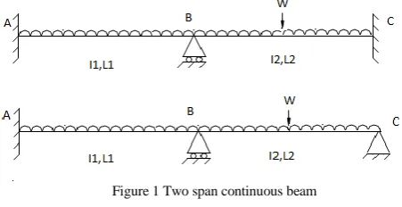
For the present study of innovative approximate analysis two span continuous beam is considered as per Figure 1. Relative deformation coefficient(Cr) and fixity coefficient(Cf)has been obtained. To perform this calculation excel spread sheets has been utilized.
Figure 1 Two span continuous beam
VI.PARAMETRIC STUDY
Analysis has been perform for two span continuous beam as per Figure 1 and obtained the values for Relative deformation coefficient(Cr) and fixity coefficient(Cf) with the Equation (1) & (2). Sample calculations are depicted for case:1 and tabulated in Table 1.Similarly obtain the values for case :2 to 4. No of spans = 2
Span length for the first span = L1 Span length for the second span = L2 Inertia first span = I1
Inertia first span = I2
Uniformly distributed load for both span = W Variation in span length = 0.1
Variation in I = 0.1
For parametric study as per support condition following four cases are considered.
IJEDR1302003 INTERNATIONAL JOURNAL OF ENGINEERING DEVELOPMENT AND RESEARCH | IJEDR Website: www.ijedr.org | Email ID: [email protected] 14 MB = ∑ (FEM x AD) (6)
Where FEM = Fixed End Moment Case:1
Relative deformation coefficient and Fixity coefficient are obtain with variation in span length L2 of 0.1 considering far end fixed.
Case:2
Relative deformation coefficient and Fixity coefficient are obtain with variation in span length L2 of 0.1 considering far end hinge.
Case:3
Relative deformation coefficient and Fixity coefficient are obtain with variation in I2 of 0.1 considering far end fixed. Case:4
Relative deformation coefficient and Fixity coefficient are obtain with variation in I2 of 0.1 considering far end hinge.
TABLE 1 Cr-B and Cf-B for case:1
L1 L2 Cr-B Cf-B
1 0.1 0.0455 0.9773
1 0.2 0.0833 0.9584
1 0.3 0.1154 0.9423
1 0.4 0.1429 0.9286
1 0.5 0.1667 0.9167
1 0.6 0.1875 0.9063
1 0.7 0.2059 0.8971
1 0.8 0.2222 0.8889
1 0.9 0.2368 0.8816
1 1 0.25 0.875
1 1.1 0.2619 0.8691
1 1.2 0.2727 0.8637
1 1.3 0.2826 0.8587
1 1.4 0.2917 0.8542
1 1.5 0.3 0.85
1 1.6 0.3077 0.8462
1 1.7 0.3148 0.8426
1 1.8 0.3214 0.8393
1 1.9 0.3276 0.8362
1 2 0.3333 0.8334
1 2.1 0.3387 0.8307
1 2.2 0.3438 0.8281
1 2.3 0.3485 0.8258
1 2.4 0.3529 0.8236
1 2.5 0.3571 0.8215
1 2.6 0.3611 0.8195
1 2.7 0.3649 0.8176
1 2.8 0.3684 0.8158
1 2.9 0.3718 0.8141
1 3 0.375 0.8125
1 3.1 0.378 0.811
1 3.2 0.381 0.8095
1 3.3 0.3837 0.8082
1 3.4 0.3864 0.8068
1 3.5 0.3889 0.8056
1 3.6 0.3913 0.8044
1 3.7 0.3936 0.8032
1 3.8 0.3958 0.8021
1 3.9 0.398 0.801
1 4 0.4 0.8
1 4.1 0.402 0.799
1 4.2 0.4038 0.7981
1 4.3 0.4057 0.7972
1 4.4 0.4074 0.7963
1 4.5 0.4091 0.7955
1 4.6 0.4107 0.7947
1 4.7 0.4123 0.7939
1 4.8 0.4138 0.7931
1 4.9 0.4153 0.7924
1 5 0.4167 0.7917
1 5.1 0.418 0.791
1 5.2 0.4194 0.7903
1 5.3 0.4206 0.7897
1 5.4 0.4219 0.7891
1 5.5 0.4231 0.7885
1 5.6 0.4242 0.7879
1 5.7 0.4254 0.7873
1 5.8 0.4265 0.7868
1 5.9 0.4275 0.7863
1 6 0.4286 0.7857
1 6.1 0.4296 0.7852
1 6.2 0.4306 0.7847
1 6.3 0.4315 0.7843
1 6.4 0.4324 0.7838
1 6.5 0.4333 0.7834
1 6.6 0.4342 0.7829
1 6.7 0.4351 0.7825
1 6.8 0.4359 0.7821
1 6.9 0.4367 0.7817
1 7 0.4375 0.7813
1 7.1 0.4383 0.7809
1 7.2 0.439 0.7805
1 7.3 0.4398 0.7801
1 7.4 0.4405 0.7798
1 7.5 0.4412 0.7794
1 7.6 0.4419 0.7791
1 7.7 0.4425 0.7788
1 7.8 0.4432 0.7784
1 7.9 0.4438 0.7781
1 8 0.4444 0.7778
1 8.1 0.4451 0.7775
1 8.2 0.4457 0.7772
1 8.3 0.4462 0.7769
1 8.4 0.4468 0.7766
1 8.5 0.4474 0.7763
1 8.6 0.4479 0.7761
1 8.7 0.4485 0.7758
1 8.8 0.449 0.7755
1 8.9 0.4495 0.7753
IJEDR1302003 INTERNATIONAL JOURNAL OF ENGINEERING DEVELOPMENT AND RESEARCH | IJEDR Website: www.ijedr.org | Email ID: [email protected] 15
1 9.1 0.4505 0.7748
1 9.2 0.451 0.7745
1 9.3 0.4515 0.7743
1 9.4 0.4519 0.7741
1 9.5 0.4524 0.7738
1 9.6 0.4528 0.7736
1 9.7 0.4533 0.7734
1 9.8 0.4537 0.7732
1 9.9 0.4541 0.773
1 10 0.4545 0.7728
VIII. APPLICATION
To demonstrate the application of innovative approximate approach problem of Two-span continuous beam as per Figure-2 is selected. Sample calculations are depicted in Table Figure-2 & 3 for joints and finally comparisons with exact values are presented in Table 4.
Figure 2 Two span continuous beam problem
TABLE 2 MA
Joint A B C
Cr - 0.36 0
Cf - 0.81 1
AD 1 0.36 0
FEM 7.5 -5.8333 13.3333
AD* FEM 7.5 -2.099 0
MA =∑ AD* FEM=5.401 kN.m (using chart of Cr-B) Actual value of MA =5.8332 kN.m
Percentage Error = -7.4093 % TABLE 3 MC
Joint A B C
Cr 0 0.36 -
Cf 1 0.81 -
AD 0 0.36 1
FEM 7.5 5.8333 13.3333
AD* FEM 0 2.099 13.3333
MC =∑ AD* FEM=15.4323 kN.m(using chart of Cr-B) Actual value of MC =14.5833 kN.m
Percentage Error = 5.8217 %
TABLE 4 Table of Moment comparison and percentage error
Joi nt
Actual moment in
kN.m
Computed moment considering chart of Cr-B
kN.m
Percentage error
A 5.8332 5.401 -7.4093
B 10.8332 11.2499 3.8456
C 14.5833 15.4323 5.8217
Figure 3 - Cr-B Two span continuous beam far end Fixed support
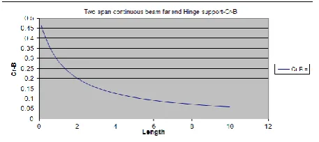
Figure 4-Cr-B Two span continuous beam far end Hinge support
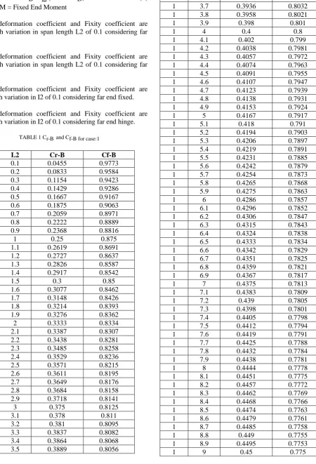
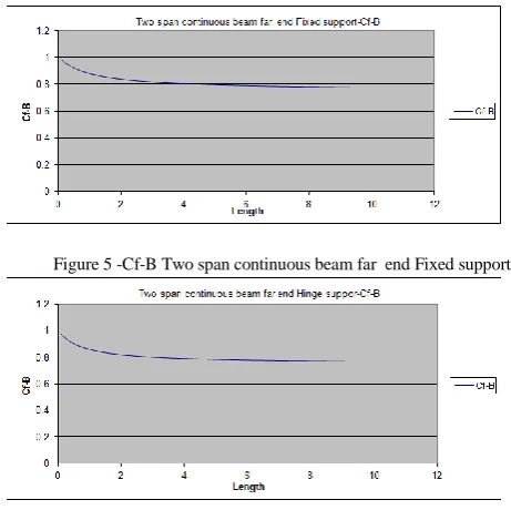
Figure 5 -Cf-B Two span continuous beam far end Fixed support
IJEDR1302003 INTERNATIONAL JOURNAL OF ENGINEERING DEVELOPMENT AND RESEARCH | IJEDR Website: www.ijedr.org | Email ID: [email protected] 16 Figure 7-Cr-B Two span continuous beam far end Fixed support
Figure 8-Cr-B Two span continuous beam far end Hinge support
Figure 9-Cf-B Two span continuous beam far end Fixed support
Figure 10-Cf-B Two span continuous beam far end Hinge support
IX. RESULTS AND DISCUSSION
(1).From the Fig.3& 4, it is observed that if one can vary the length parameter by 0.1 in the range of 1 to 10 m the value of
Relative deformation coefficient(Cr) obtained in the range of 0.0455 to 0.4545 & 0.0588 to 0.4651with considering far end fixed and far end hinged respectively.
(2). From the Fig. 5&6, it is observed that if one can vary the length parameter by 0.1 in the range of 1 to 10 m the value of fixity coefficient(Cf) obtained in the range of 0.9773 to 0.7728 & 0.9706 to 0.7675 with considering far end fixed and far end hinged respectively.
(3). From the Fig. 7& 8, it is observed that if one can vary the I parameter by 0.1 in the range of 1 to 10 m the value of Relative deformation coefficient(Cr) obtained in the range of 0.4545 to 0.0455 & 0.4651 to 0.0588 with considering far end fixed and far end hinged respectively.
(4). From the Fig. 9 & 10, it is observed that if one can vary the I parameter by 0.1 in the range of 1 to 10 m the value of fixity coefficient(Cf) obtained in the range of 0.7728 to 0.9773 & 0.7675 to 0.9706 with considering far end fixed and far end hinged respectively.
(5).From Table 4 it is observed that error is less than 8% between actual moment and calculated by innovative method.
X. CONCLUSION
From the above results and discussion it can be concluded that one has to accept that an approximate method for the solution of indeterminate structure like continuous beam giving numerically compatible results.Method evolved is innovative,easy and userfriendly.
REFERENCES
[1] Behr R.A., Goodspeed C.H., ―potential errors in structural analysis‖, Journal of structural engineering, vol.116, No.11, November 1990.
[2] Behr, R.A., E.J.Grotton and C.A.Dwinal (1990) ― Revised method of approximate structural analysis‖, Journal of structural division, ASCE, vol-116, no-11, 3242-3248.
[3] Dr. Terje Haukaas, ―Lecture notes posted in location www.inrisk.uk.ca ‖, British Columbia.
[4] Khuda S.N, ―design aid for continuous beam‖, Military institute of science and technology.
[5] Okonkwo, Aginam and Chidolue, ―Analysis of Internal support moments of continuous beams of equal spans using simplified mathematical model approach.‖, Journal of Sciences and Multidisciplinary Research, Volume 2, September 2010. [6] Amer M Ibrahim, ―Parametric study of continuous concrete
beam‖, Jordan journal of civil engineering Vol-4,No 3,2010. [7] Reddy, C.S ―Basic Structural Analysis‖, Tata Mc-Graw Hill,
New Delhi. .
[8] Wang, C. K., ―Intermediate structural analysis‖, Mc-Grow Hill