ISSN(Online): 2319-8753 ISSN (Print): 2347-6710
International Journal of Innovative Research in Science,
Engineering and Technology
(A High Impact Factor & UGC Approved Journal) Website: www.ijirset.com
Vol. 6, Issue 8, August 2017
Improving the Performance of PV System by
using Fuzzy logic controller and SEPIC
Converter under Partial Shading Condition
K.Vedaprakash 1, Sri.P.Balamurali 2,Mr.T.Manmadha Rao3
P.G. Scholar, Department of EEE, AITAM Engineering College (Autonomous), Andhra Pradesh, India 1
Asso. Professor, Department of EEE, AITAM Engineering College (Autonomous), Andhra Pradesh, India 2
Asst. Professor, Department of EEE, AITAM Engineering College (Autonomous), Andhra Pradesh, India 3
ABSTRACT: This paper investigates the comparative study of Photovoltaic (PV) system with maximum power point tracking algorithms (MPPT): Incremental conductance and Fuzzy logic control methods to get maximum power using Different DC-DC converters like boost converter, Buck converter, Buck-Boost and Sepic converter, Among all these combinations we get maximum power output and efficiency of PV system by using Fuzzy logic control MPPT with Sepic converter. Fuzzy logic controller provides advanced features such as fast response, good performance in terms of oscillations and to improve the efficiency. This paper also presents the behaviour of PV system under uniform and partial shaded conditions. This MPPT algorithm’s also adjusts the duty cycle of the switch in DC-DC Sepic converter for regulating the input voltage at the maximum power point and provides constant input power load regardless of changing climatic conditions. The proposed system is simulated using MATLAB/Simulink model.
KEYWORDS: Photovoltaic system, incremental conductance method (INC), Fuzzy logic control, Uniform and Partial Shaded Conditions (USC and PSC), Sepic converter, Modelling and Simulation.
I. INTRODUCTION
The renewable energy sources are also called as non-conventional type of energy sources. Which are continuously renewed by natural process. It includes, solar energy, bio-energy - bio-fuels, wind energy, ocean energy, tidal energy and hydropower etc., are some of the examples of renewable energy sources. A renewable energy system convert the energy found in sunlight, falling-water, wind, sea-waves, geothermal heat, or biomass into a usable form, such as in the form of heat energy or electrical energy. The majority of the renewable energy comes either directly or indirectly from sun and it can never be fatigued, and therefore it is called as renewable energy Source.
Nowadays, on a commercial level and on a small scale, individual users are frequently using PV arrays because PV Systems have Specific advantages, it can be used for both low power and high power applications, fuel free etc. but this PV systems suffers from some of the atmospheric conditions like temperature and irradiance so, all are trying to extract a maximum amount of power from PV panel. The output power and the power voltage (P-V) characteristic of PV array are totally dependent on the temperature and solar irradiance. Therefore, if these atmospheric parameters fluctuate rapidly, then the maximum power point of the P-Vcurve of PV array also fluctuates very rapidly. This rapid fluctuation of the MPP may be, in accordance with the uniform shading of the PV panel or may be in accordance to the partially shaded due to the clouds, tall building, trees, and raindrops.
ISSN(Online): 2319-8753 ISSN (Print): 2347-6710
International Journal of Innovative Research in Science,
Engineering and Technology
(A High Impact Factor & UGC Approved Journal) Website: www.ijirset.com
Vol. 6, Issue 8, August 2017
II. RELATED WORK
In recent years, a large number of techniques have been proposed for tracking the maximum power point. Maximum power point varies and depends on the temperature of Solar cell or also depends on the preset insolation level. This MPPT with a dc-dc sepic converter is used for tracking or extracting the maximum power from the solar PV module and transferring this maximum power from the solar PV module to the load. There are a large number of algorithms that are able to track MPPs.Some of them are more complicated, such as perturbation and observation or the incremental conductance method and Some of them are simple, such as those based on voltage and current feedback, So we are using such a simple method Fuzzy logic control MPPT with Sepic converter.
This paper also proposed to distinguish between the global peak (GMPP) and local peak (LMPP). The topmost peak is known as global maximum power point and rests all peaks are known as local maximum power point. During partial shading, global and local maximum power points are produced. Once the local maximum is reached, P&O methods fluctuate around that point. To overcome the issue, an innovative method of incremental conductance MPPT has been developed to reduce the oscillations and stabilize the maximum power point. But fuzzy logic controller provides advanced features such as fast response, good performance in terms of oscillations to reaches global maximum point so, fuzzy logic controller is designed and analyzed in this paper and this can be compared with INC Algorithm.
III. MODELING OF SOLAR PV SYSTEM
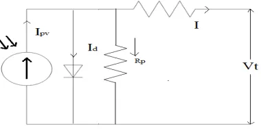
Solar Cells or Photo Voltaic Cells are devices or simply transducers which convert the energy available from the sun directly into electrical energy which is in the form of a DC i.e. electromagnetic radiation of solar energy can be directly converted to electricity through photovoltaic effect. PV cell when placed in the sunlight, photons with energy greater than the band-gap energy of the semiconductor develops electron-hole pairs proportional to the incident irradiation. Solar cells can be connected in series and parallel depending upon the desired voltage or current. This series or parallel connected solar module form a string and the combination of such string in series and parallel gives a solar array. Shows Fig (1) below equivalent circuit of PV cell and the series resistance Rs, which is an existingresistance
opposing the flow of current. The parallel the parallel resistance Rpis inversely proportional to the leakage current w. r.
t. the ground and this value becomes very small and negligible.
Fig. 1. Equivalent circuit model of PV cell
PV array output current
I = I −I − (1)
Photo Current
Ipv = (T−Tref) a + −1 I (2)
Diode current
ISSN(Online): 2319-8753 ISSN (Print): 2347-6710
International Journal of Innovative Research in Science,
Engineering and Technology
(A High Impact Factor & UGC Approved Journal) Website: www.ijirset.com
Vol. 6, Issue 8, August 2017
Voltage across Diode
V = b(T−T ) + [(T−T ) a + −1 I ]R (4) Where
I=PV array output current in (A) Id=Diode current (A)
Ipv=Photo current or current generated by the incident of light (A)
Table (1) shown below gives complete specifications of matlab designed PV system. Short circuit current can be found by connecting two output terminals of PV system directly.Temparature of the PV cell is maintained at constant room temperature and the irradiance levels can be changed according to our required output power because the output power my changes with respect to irradiance.
Table 1: Specification of PV module
Variable Name of the variable Rated values
Isc Short circuit current 25.44 A
T Temparature of the PV cell 2730C
Tref Reference Temparature of PV cell 250 C
S Irradiance values 600,400,200(under
partial shading)W/m2
Sref Reference value of irradiance 1000 W/m2
Rs Series resistance 2.2 ohms
IV. PROPOSED MPPT TECHNIQUES
A. Incremental conductance MPPT technique
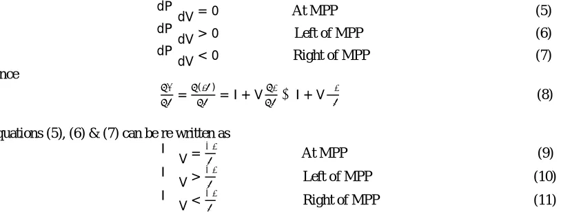
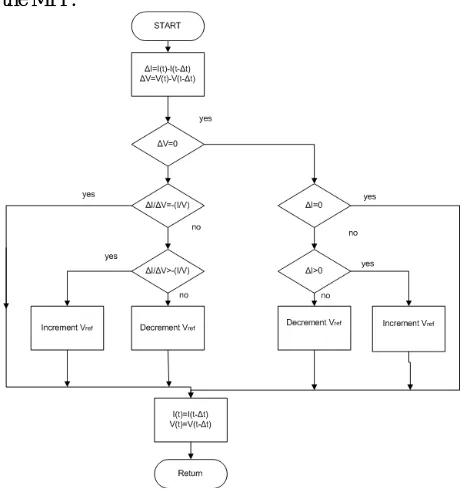
The MPP can thus be tracked by comparing the instantaneous conductance (I/V) to the incremental conductance (ΔI/ΔV) as shown in the flowchart in Fig. 2. The incremental conductance method is based on the fact that the slope of the PV array Power curve is zero at the MPP, positive on the left of the MPP, and negative on the right, as given by below equations.
dP dV = 0 At MPP (5)
dP dV > 0
Left of MPP
(6)
dP dV < 0
Right of MPP
(7)
Since
= ( )= I + V ≅I + V∆
∆ (8)
Equations (5), (6) & (7) can be re written as
∆I ∆V =
At MPP (9)
∆I ∆V >
Left of MPP
(10)
∆I ∆V <
Right of MPP
(11)
Vrefis the reference voltage at which the PV array is forced to operate. At the MPP, Vref equals to VMPP. Once the MPP
is reached, the operation of thePV array is maintained at this point unless a change in ΔIis noted, indicating a change in atmospheric conditions and the MPP. The algorithm decrements or increments Vref to track the new MPP. Effective
way of performing the INC technique is to use the instantaneous conductance and the incremental conductance to generate an error signal
ISSN(Online): 2319-8753 ISSN (Print): 2347-6710
International Journal of Innovative Research in Science,
Engineering and Technology
(A High Impact Factor & UGC Approved Journal) Website: www.ijirset.com
Vol. 6, Issue 8, August 2017
We know that e goes to zero at the MPP.
Fig. 2. Flow chart for the Incremental conductance MPPT
Below figure (3) shown MATLAB design of INC MPPT.By using this we can generate gate pulses to the switch in the DC-DC converter and to control output power. This technique can be operated by taking feedback voltage and current from the PV system. It Provide the duty cycle according to the maximum power point wether it is positive or negative by comparing the calculated instantaneous conductance with change in conductance.
Fig. 3. MATLAB Simulated Algorithm for Incremental conductance MPPT
B.Fuzzy Logic Control
Fuzzy logic control is most popular for MPPT over the last decade. Fuzzy logic controllers have the advantages of workingwith imprecise inputs, not needing an accurate mathematical model, and handling nonlinearity. Fuzzy logic control generally consists of three stages: fuzzification, rule base table lookup, and Defuzzification. During fuzzification, numerical input variables are converted into linguistic variables based on a membership function similar to Fig. 4 below.
ISSN(Online): 2319-8753 ISSN (Print): 2347-6710
International Journal of Innovative Research in Science,
Engineering and Technology
(A High Impact Factor & UGC Approved Journal) Website: www.ijirset.com
Vol. 6, Issue 8, August 2017
In this case, five fuzzy levels are used: NB (negative big), NS (negative small), ZE (zero), PS (positive small), and PB (positive big). In Fig. 4, a and b are based on the range of values of the numerical variable. The membership function is sometimes made less symmetric to give more importance to specific fuzzy levels. The inputs to a MPPT fuzzy logic controller are usually an error E and a change in error ΔE. The user has the flexibility of choosing how to compute E and ΔE. Since dP/dV vanishes at the MPP.
E(n) =
[ ( ) ( )][ ( ) ( )]
(13)
And
∆E(n) = E(n)−E(n−1) (14)
Once E and ΔE are calculated and converted to the linguistic variables, the fuzzy logic controller output, which is typically a change in duty ratio ΔD of the power converter, can be looked up in a rule base table such as Table II.
Table 2: Fuzzy rules base table
The linguistic variables assigned to ΔD for the different combinations of E and ΔE is based on the power converter being used and also on the knowledge of the user. If, for example, the operating point is far to the left of the MPP, that is E is PB, and ΔE is ZE, then we want to largely increase the duty ratio that is ΔD should be PB to reach the MPP. In the Defuzzification stage, the fuzzy logic controller output is converted from a linguistic variable to a numerical variable still using a membership function. This provides an analog signal that will control the power converter to the MPP. MPPT fuzzy logic controllers have been perform well under varying atmospheric conditions.
V. DC-DC CONVERTERS
There are different types of dc-dc converters. Buck, boost, buck-boost and Sepic converter topologies have been developed in this paper and from these converters sepic converter meets specific demands.
A. Buck converter:
The buck converter is also known as the step-down converter. Buck converters will produce ripples on the PV module side currents and thus require a larger value of input capacitance on the module side. A buck converter using a power MOSFET shown in Fig. 5.
Fig. 5. DC-DC Buck converter ΔE
E
NB NS NE PS PB
NB ZE ZE NB NB NB
NS ZE ZE NS NS NS
ZE NS ZE ZE ZE PS
PS PS PS PS ZE ZE
ISSN(Online): 2319-8753 ISSN (Print): 2347-6710
International Journal of Innovative Research in Science,
Engineering and Technology
(A High Impact Factor & UGC Approved Journal) Website: www.ijirset.com
Vol. 6, Issue 8, August 2017
B.Boost converter:
The boost converter is also known as the step-up converter. In this boost converter the output voltage is greater than the input voltage. Large output capacitor is required to reduce ripple voltage as output current is pulsating. Slower transient response. A boost converter using a power MOSFET shown in Fig. 6.
Fig. 6. DC-DC Boost converter
C.Buck-Boost converter:
Buck boost converter requires input filter to reduce current ripple and to meet electromagnetic interference (EMI) requirements as input current is pulsating due to switching of power switch. Also output current is discontinuous and hence large output capacitor is required to reduce ripple voltage. Even though buck-boost converter is able to step up or step down input voltage it gives negative output voltage with respect to ground. Moreover, presence of right half zero in continuous conduction mode makes feedback loop compensation difficult. A Buck-Boost converter using a power MOSFET shown in Fig. 7.
Fig. 7. DC-DC Buck-Boost converter
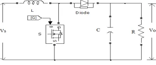
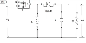
D.Sepic converter:
To overcome the above disadvantages of all above converters by usingSepic converter. This is the one of the DC-DC converter and This single ended primary inductor converter (SEPIC) can have its output voltage higher or lower than its input voltage unlike boost converter or buck converter Although buck- boost converter is also able to give higher as well as lower output voltage than its input voltage, it's output voltage is negative with respect to ground unlike SEPIC converter, which provides positive output voltage. A Sepic converter using a power MOSFET shown in Fig. 8.
Fig. 8. DC-DC Sepic converter
ISSN(Online): 2319-8753 ISSN (Print): 2347-6710
International Journal of Innovative Research in Science,
Engineering and Technology
(A High Impact Factor & UGC Approved Journal) Website: www.ijirset.com
Vol. 6, Issue 8, August 2017
Table 3: Specification of Sepic Converter
Variable Name of the variable Rated values
L1=L2 Inductance in Henry 0.01H
C1=C2 Capacitance in Farad 2mF
R Load resistance in ohms 500 ohms
VI. SIMULINK MODELING OF SOLAR PV SYSTEM
Modelling can be done in MATLAB by many ways; common methods includes by programming and using SIMULINK modelling. Modelling a PV panel using SIMULIK is explained in this section. As explained above, the PV panel is influenced by temperature, Irradiance, etc. Step wise blocks are made and finally, all are combined to get the PV panel. Below figure (9) shown design of PV system to get PV current, this can be done by standard equations and reference values as already mentioned above.
Fig. 9. Calculation of PV Current
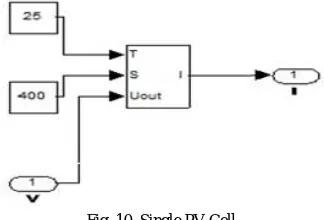
Below figure (10) shown represents single PV cell subsystem created for the above figure (9).We can give constant reference temperature of 250C and irradiance value 400W/m2.From this single cell we got less value of output current, to overcome the this problem by connecting three cells in parallel as shown in figure(11).
Fig. 10. Single PV Cell
ISSN(Online): 2319-8753 ISSN (Print): 2347-6710
International Journal of Innovative Research in Science,
Engineering and Technology
(A High Impact Factor & UGC Approved Journal) Website: www.ijirset.com
Vol. 6, Issue 8, August 2017
Fig. 11 Parallel Connected PV Module
VII. SIMULATION RESULTS
CASE 1: Uniform shaded Condition
During uniform shading, the PV system is tested under same irradiation levels. Three modules are uniformly Shaded with an irradiance level of 400W/m2 and constant temperature of 250C. The power level can be increased by increasing the irradiance value and this can be verified by this simulation. Below figure (12) shown P-V and I-V characteristics under uniform shading. Under this condition we got only one local maximum point, this can be easily tracked by MPPT.
Fig. 12. P-V and V-I Characteristic of solar array with uniform irradiance
CASE 2: Partial shaded Condition
During partial shading, the PV system is tested under different irradiation levels. Three modules are partially Shaded with an irradiance level of 200, 400 and 600W/m2 and constant temperature of 250C.Below figure (13) shown P-V and I-V characteristics under partial shading condition.
ISSN(Online): 2319-8753 ISSN (Print): 2347-6710
International Journal of Innovative Research in Science,
Engineering and Technology
(A High Impact Factor & UGC Approved Journal) Website: www.ijirset.com
Vol. 6, Issue 8, August 2017
Fig. 13. P-V and V-I Characteristic of solar array with non-uniform Irradiance (Shading Effect)
CASE 3: Simulated outputs with Incremental conductance MPPT Algorithm
PV module is simulated with Incremental conductance MPPT and this PV system output voltage applied to
different converters. The output voltages of different converters shown in Figure 14, for constant duty cycle δ=0.5
Fig. 14. Output voltages of different converters along with incremental conductance MPPT.
CASE 4: Simulated outputs with Fuzzy logic control MPPT Algorithm
PV module is simulated with Fuzzy logic control MPPT and this PV system output voltage applied to different
converters. The output voltages of different converters shown in Figure 15, for constant duty cycle δ=0.5.Observe the
below output voltage levels, we got greater positive voltage level with combination of fuzzy logic controller MPPT algorithm and Sepic converter as compared to all other converters and this voltage also greater than the combination of incremental conductance algorithm and sepic converter.
Fig. 15. Output voltages of different converters along with Fuzzy logic controller MPPT.
ISSN(Online): 2319-8753 ISSN (Print): 2347-6710
International Journal of Innovative Research in Science,
Engineering and Technology
(A High Impact Factor & UGC Approved Journal) Website: www.ijirset.com
Vol. 6, Issue 8, August 2017
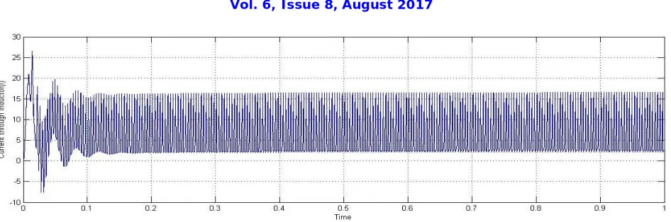
Fig. 16. Current flowing in to the inductor L1 for continues mode operation of sepic converter along with Fuzzy logic controller MPPT.
From the table (4) given below gives comparative analysis of proposed MPPT techniques and this analysis clearly indicates Fuzzy logic control algorithm along with Sepic Converter gives increased positive output voltage and this voltage will reach steady state within the less time i.e. settling time of this combination (Fuzzy logic control with Sepic converter) is very less.
Table 4: Comparison of proposed MPPT Algorithms
Specification Incremental Conductance Algorithm Fuzzy logic controller algorithm
Boost Converter Buck Converter Buck-Boost Sepic converter Boost Converter Buck Converter Buck-Boost Sepic Converter
Settling time of Voltage(sec)
0.1 0.05 0.25 0.3 0.6 0.1 0.8 0.4
Output Voltage(volts)
700 240 -500 900 1100 300 -1000 1300
Accuracy Medium More
Tracking Speed Medium Fast
Complexity More Less
VIII. CONCLUSION
The energy conversion of entire system has been designed in MATLB-SIMULINK environment. By observing the above simulated results we got improved values of voltage with the combination of combination of fuzzy logic controller MPPT algorithm and Sepic converter as compared to all other combinations and this output voltage has less harmonic content. During the simulations, it was confirmed that, with a well designed system including a proper converter and selecting an efficient algorithm, the implementation of MPPT is simple and can be easily constructed to achieve an acceptable Power levels Regardless of changing Environmental conditions. The results also indicate that the proposed control system is capable of tracking the PV array at maximum power and thus improves the efficiency of the PV system due to good dynamic response and good tracking accuracy.
REFERENCES
[1]. J.A. Gow, C.D. Manning, “Development of a photovoltaic array model for use in power-electronics simulation studies”, IEE Proc.Electr.Power Appl, Vol 146, No.2, pp. 193-200, March. 1999.
[2]. H. Patel and V. Agarwal, “Matlab-Based Modelling to Study the Effects of Partial Shading on pv Array Characteristics,” IEEE Transactions on Energy Conversion, Vol.23, No. 1, pp. 302-310, 2008.
ISSN(Online): 2319-8753 ISSN (Print): 2347-6710
International Journal of Innovative Research in Science,
Engineering and Technology
(A High Impact Factor & UGC Approved Journal) Website: www.ijirset.com
Vol. 6, Issue 8, August 2017
[4]. Y.-C. Kuo, T.-J. Liang and J.-F. Chen, “Novel maximum-power-point tracking controller for photovoltaic energy conversion system,” IEEE Trans. Ind. Electron, vol. 48, no. 3, pp. 594–601, Jun. 2001.
[5]. G. J. Yu, Y. S. Jung, J. Y. Choi, I. Choy, J. H. Song, and G. S. Kim, “A novel two-mode MPPT control algorithm based on comparative study of existing algorithms,” in Conf. Record Twenty-Ninth IEEE Photovoltaic Spec. Conf., pp. 1531–1534, 2002.
[6]. K.Kobayashi, I. Takano, and Y. Sawada, “A study on a two stage maximum power point tracking control of a photovoltaic system under partially shaded insolation conditions,” in IEEE Power Eng. Soc. Gen.Meet.,pp. 2612–2617, 2003.
[7]. M. A. S. Masoum, H. Dehbonei, and E. F. Fuchs, “Theoretical and experimental analyses of photovoltaic systems with voltage and current-based maximum power-point tracking,” IEEE Trans,Energy Convers., vol. 17, no. 4, pp. 514–522, Dec. 2002.
[8]. Azadeh Safari and Saad Mekhilef, “Simulation and Hardware Implementation of Incremental Conductance MPPT With Direct Control Method Using Cuk Converter”, IEEE Trans. on Ind. electronics, vol. 58, pp.no. 4, April 2011.
[9]. Francisco Paz, and Martin Ordonez, “Zero Oscillation and Irradiance Slope Tracking for Photovoltaic MPPT”, IEEE Trans. On Ind electronics, vol. 61, pp.no. 11, Nov. 2014.
[10]. Athimulam Kalirasu, Subharensu Sekar Dash, “Simulation of Closed Loop Controlled Boost Converter for Solar Installation”, Serbian Journal of Electrical Engineering ,Vol. 7, No. 1,pp. 121-130, May 2010.
BIOGRAPHY
Mr.K.Vedaprakash received his B.Tech Degree in Electrical and Electronics Engineering from Sri Sivani College of engineering, Srikakulam, Andhra Pradesh, India in 2013. Currently pursuing M.Tech in Aditya Institute of Technology and Management (Autonomous), Tekkali, and Andhra Pradesh, India. His research interests include Renewable energy systems, Power systems and power electronics.
Sri.P.Balamurali completed his graduation in Electrical and Electronics Engineering from JNTUK in 2001 and received his M.Tech in Power Systems from NIT Jamshedpur, India in 2006. Currently pursuing Ph.D from NIT Jamshedpur. He served as an Assistant Professor and Associate Professor in various Engineering colleges from 11 years and at present; he is working as Associate Professor in the Department of Electrical and Electronics Engineering in AITAM College of Engineering, Tekkali, and Andhra Pradesh, India. He had published many papers in national and international journals and conferences. His areas of interest are Power systems, Renewable energy sources and Control systems, Circuit Analysis, Electrical Machines.