ISSN(Online): 2319-8753 ISSN (Print): 2347-6710
I
nternational
J
ournal of
I
nnovative
R
esearch in
S
cience,
E
ngineering and
T
echnology
(An ISO 3297: 2007 Certified Organization)
Vol. 5, Issue 6, June 2016
Effect of Exit Diameter on the Performance of
Converging – Diverging Annular Nozzle Using
CFD
Arjun Kundu1, Devyanshu Prasad2, Sarfraj Ahmed3
1
P.G. Student, Department of Mechanical Engg, SSCET, Bhilai, India 2
Asst Professor, Department of Mechanical Engg, SSCET, Bhilai, India 3
Asst Professor, Department of Mechanical Engg, GDRCET, Bhilai, India
ABSTRACT:A Converging – diverging gas nozzle is used to obtain supersonic speed .The project work is focused on analyzing the converging-divergingannular nozzle with the help of computational fluid dynamics. A Nozzle of certain dimension is taken and it is modelled in Creo 2.0 parametric and then it is imported to ANSYS 14.0 Workbench and the analysis is carried out for two different exit diameter of the nozzle. The pressure, temperature and velocity were kept same in both the cases at inlet. The simulation has been done using ANSYS Workbench (CFX module) and the effect of exit diameter is studied. The result of simulation was different in each case .The increase in velocity, decrease in temperature and the drop in pressure was more for nozzle with smaller exit diameter than nozzle for large exit diameter.
KEYWORDS: CFD, Annular, Exit Diameter
I.INTRODUCTION
In Rocket engine today the need of converging diverging nozzle is a need. It was invented by Carl G.P DE LAVAL in the nineteen century in the experiment of steam turbine. Today we are mostly using DE-LAVAL turbine for running steam turbine. This principle was first used in Rocket by Robert Goddard. DE –LAVAL found that the most effective conversion is when nozzle is narrowed first, increasing the speed of air to the speed of sound and then expanded again[1]. Above the speed of sound this expansion cause increase of speed of fluid and let to conversation of heat energy into motion. The flow in the nozzle is very rapid with little frictional loss. Nozzle are used to control the rate of flow, speed, direction, mass, pressure, velocity, temperature that emerges out of them. Nozzle is used to convert chemical energy produced by the combustion chamber into kinetic energy. Nozzle convert the low velocity, high pressure or high temperature into high velocity, low pressure and low temperature at the exit of nozzle [3].
If the nozzle pressure ratio is high the velocity will be in the sonic range at section the nozzle is said to be chocked. The gas flowing through the nozzle is isentropic flow having means entropy is nearly in constant values. Mach number is also very important because if the Mach number is 1 it means that it can reach speed of sound which vary with square root of temperature so it can reach speed far more than speed at sea level [4]. It is used in rocket engine, Jet engines, steam turbine mainly for producing supersonic speed having inlet as subsonic. In this paper circular nozzle is used which having less weight and more efficient as compared to other nozzle.
II. THEORETICAL BACKGROUND NOZZLE BASIC CONCEPTS
ISSN(Online): 2319-8753 ISSN (Print): 2347-6710
I
nternational
J
ournal of
I
nnovative
R
esearch in
S
cience,
E
ngineering and
T
echnology
(An ISO 3297: 2007 Certified Organization)
Vol. 5, Issue 6, June 2016
works with any external source. They are efficient in the sense that they light in weight and produces high supersonic speed. The amount of thrust produce depend upon the mass flowing through the nozzle, Exit velocity of gas and exit pressure For better efficiency nozzle diameter can be increased up to a limit. Both velocity and pressure is a must for a better nozzle [6].
K-epsilon turbulence Model –
This type of model is used in computational fluid dynamics to stimulate for turbulent mean flow condition. This model is generally two equation model by:-
• First transport variable help in determine the energy in turbulence which is called turbulent kinetic energy. • Second one is the turbulent dissipation (ε) is used to determine the rate of dissipation of turbulent kinetic energy.
Turbulent kinetic energy (TKE) -
Turbulent kinetic energy (TKE) –It is the mean kinetic energy per unit mass having relation with eddies in the turbulent flow .It is measured by root mean square velocity fluctuation.
Turbulence Dissipation Rate -
Turbulence dissipation rate is the rate at which turbulent K.E is converted into thermal energy. Its S.I unit of e is J/Kg. s=m2/s3 [4].
Nozzle Dimensions
Parameters Nozzle 1 Nozzle 2
Inlet Diameter 120 cm 120 cm
Outlet Diameter 60 cm 53 cm
Throat Diameter 50 cm 50 cm
Convergent Length 70 cm 70 cm
Divergent Length 80 cm 80 cm
Total Length 150 cm 150 cm
III.CFD ANALYSIS
Computational fluid dynamics is a branch of fluid dynamics which depend on numerical method and algorithm to solve and analyze the problem of fluid flow. It can also be applied to problem which has transportation phenomenon
Computational fluid dynamics is an art of replacing the integral or partial derivative equation with the discretized algebraic form which are turn to solve to obtain number for the flow field with respect to time and space. CFD can compute millions of task that is impossible for the human beings. These basic principle which is to be used here in a CFD are (a) mass is conserved (b) Newton’s second law of motion (c) Energy is conserved. These physical principle is applied to a model of the flow which result in continuity, momentum and energy governing equation then the boundary condition is applied or developed and fitted entered to the governing equation.[7]
BOUNDARY CONDITIONS
The boundary conditions for the both nozzle geometry at inlet is taken as –
Temperature = 2000oc, Velocity =30 m/sec, Air ideal gas is taken as working fluid and the reference pressure is taken as 1.0000e+00 (Atm) .At inlet condition the Flow regimes is subsonic, static temperature is taken and Turbulence is having medium intensity and eddy viscosity ratio.
ISSN(Online): 2319-8753 ISSN (Print): 2347-6710
I
nternational
J
ournal of
I
nnovative
R
esearch in
S
cience,
E
ngineering and
T
echnology
(An ISO 3297: 2007 Certified Organization)
Vol. 5, Issue 6, June 2016
IV. RESULT & DISCUSSION
The following results are obtained after simulation in ANSYS Workbench 14.0 (CFX module) – (1)For Nozzle 1 with exit diameter 60 cm -
Figure 1- Temperature Variation for a nozzle of 60 cm exit diameter
In first case shown in fig - 1 the temperature variation is analysed in ANSYS CFX. Here we can see at inlet the temperature is taken as [2.273 + 003]K, then it is decreasing upto throat to [2.251 + 003]K and at the exit of
nozzle the again the temperature is increasing to [2.266 + 003]K.
ISSN(Online): 2319-8753 ISSN (Print): 2347-6710
I
nternational
J
ournal of
I
nnovative
R
esearch in
S
cience,
E
ngineering and
T
echnology
(An ISO 3297: 2007 Certified Organization)
Vol. 5, Issue 6, June 2016
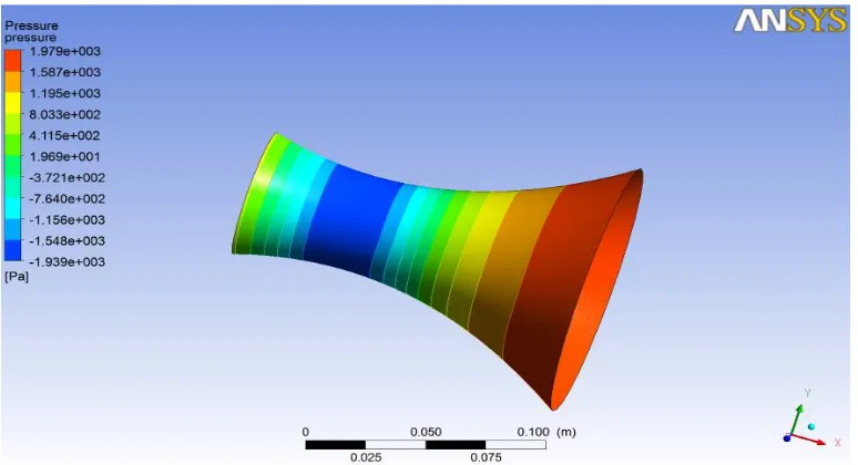
.In first case shown in fig - 2 we see that the pressure at inlet of nozzle is[1.979 + 003]Pa ,then it decreasing at the throat to [−1.548 + 003]Pa so this pressure is vaccum pressure which is below the ambient pressure and the exit of nozzle is somewhat increases upto[1.969 + 001]Pa
Figure 3-Velocity variationfor a nozzle with 60 cm exit diameter
In first case of velocity variation we can analyze in fig - 3 that at the inlet of nozzle the velocity is around [3.105 + 001]m/s which is subsonic speed, at the throat the speed is around [2.141 + 002]m/s and at the exit of nozzle we have found here the speed is[1.683 + 002]m/s.
ISSN(Online): 2319-8753 ISSN (Print): 2347-6710
I
nternational
J
ournal of
I
nnovative
R
esearch in
S
cience,
E
ngineering and
T
echnology
(An ISO 3297: 2007 Certified Organization)
Vol. 5, Issue 6, June 2016
In first case shown in fig - 4 we analyzed that momentum U in X-direction starts from some variable and increases to a variable value ,then decreases with respect to time and the momentum is almost constant with respect to time. From graph we can see momentum in Y & Z Direction almost merge and it first increases to some variable value then decreases and remain constanst with respect to time step.Mass flow rate is decreasing from intet to outlet.
Fig. 5- Heat transfer graph against accumulated time stepFig. 6- Turbulence KE & Dissociation graph against accumulated time step
In first case shown in fig - 5 the heat transfer along the nozzle can be seen in graph that from inlet heat transfer increases to some variable value, after that it decreases and then it remians constant.In first case shown in fig – 6 that turbulent kinetic energy is having higher variable value at inlet then it decreases to some variable value ,after some time it again increases and then it remains constant till the exit of nozzle. Dissoscaition rate also follows the same trend.
ISSN(Online): 2319-8753 ISSN (Print): 2347-6710
I
nternational
J
ournal of
I
nnovative
R
esearch in
S
cience,
E
ngineering and
T
echnology
(An ISO 3297: 2007 Certified Organization)
Vol. 5, Issue 6, June 2016
In second case shown in fig- 7 the temperature variation is analysed in ANSYS CFX. Here we can see at inlet the temperature is around [2.273 + 003]K,then it is decreasing upto throat to [2.246 + 003]K and at the exit of nozzle the again the temperature is increasing to [2.257 + 003]K.
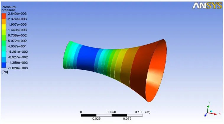
Figure 8- Pressure variation for a nozzle with 53 cm exit diameter.
In second case shown in fig -8 we see that the pressure at inlet of nozzle is[2.840 + 003]Pa ,then it decreasing at the throat to [−1.826 + 003]Pa so this pressure is vaccum pressure which is below the ambient pressure and the exit of nozzle is somewhat increases upto[4.057 + 001]Pa which is positive pressure.
Figure 9- Velocity variation for a nozzle with 53 cm exit diameter.
In second case shown in fig-9 the velocity at the inlet of nozzle is around [3.112 + 001]m/s which is subsonic speed, at the throat the speed is around [2.344 + 002]m/s and the exit of nozzle we have found here the speed of[1.836 +
ISSN(Online): 2319-8753 ISSN (Print): 2347-6710
I
nternational
J
ournal of
I
nnovative
R
esearch in
S
cience,
E
ngineering and
T
echnology
(An ISO 3297: 2007 Certified Organization)
Vol. 5, Issue 6, June 2016
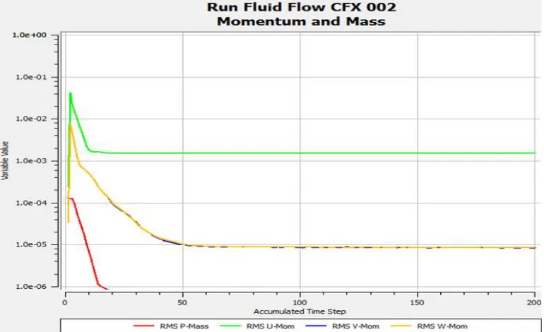
Figure 10- Mass – Momentum graph against accumulated time step.
In second case shown in fig-10 we analyzed that momentum U in X-direction starts from some variable and increases to a variable value ,then decreases with respect to time and the momentum is almost constant with respect to time. From graph we can see momentum in Y & Z Direction almost merge and it first increases to some variable value then decreases and remain constanst with respect to time step. Mass flow rate is decreasing from inlet to outlet.
Fig. 11- Heat transfer graph against accumulated time stepFig. 12- Turbulence KE & Dissociation graph against accumulated time step
ISSN(Online): 2319-8753 ISSN (Print): 2347-6710
I
nternational
J
ournal of
I
nnovative
R
esearch in
S
cience,
E
ngineering and
T
echnology
(An ISO 3297: 2007 Certified Organization)
Vol. 5, Issue 6, June 2016
Figure 13- Graph showing velocity variation along the nozzle length.
The velocity variation along the length of the nozzle during the fluid flow is shown in fig 13, for both the nozzle velocity increases but in the exit section of nozzle the velocity decreases due to turbulence and flow separation
Figure 14- Graph showing pressure variation along the nozzle length.
The pressure variation along the length of nozzle during the fluid flow is shown in fig 14, for both the nozzle it decreases but in the exit section of nozzle the pressure increases which is beneficial for obtaining thrust force.
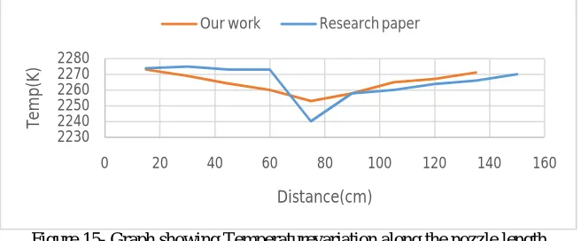
Figure 15- Graph showing Temperaturevariation along the nozzle length
.The Temperature variation along the length of nozzle during the fluid flow is shown in fig 15, for both the nozzle it decreases but in the exit section of nozzle there is a slight increase in temperature [2,8].
0 50 100 150 200 250 300 350 400 450
0 20 40 60 80 100 120 140 160
ve lo ci ty (m /s ) Distance(cm) Our work Research paper 0 1000 2000 3000 4000
0 20 40 60 80 100 120 140 160
P re ss u re (P as ) Distance(cm)
Our work Research paper
2230 2240 2250 2260 2270 2280
0 20 40 60 80 100 120 140 160
Te m p (K ) Distance(cm)
ISSN(Online): 2319-8753 ISSN (Print): 2347-6710
I
nternational
J
ournal of
I
nnovative
R
esearch in
S
cience,
E
ngineering and
T
echnology
(An ISO 3297: 2007 Certified Organization)
Vol. 5, Issue 6, June 2016
This result is showing good agreement with the research paper entitled CFD analysis on a different advanced rocket nozzles by M. Prathibha, M. S. Gupta and S. Naidu [5].
V.CONCLUSION
Computational fluid dynamics analysis has been carried out for convergent-divergent annular nozzle with two different exit diameter. In the first nozzle with exit diameter 60 cm, the increase in velocity from inlet to outlet is 137.3 m/s, the decrease in pressure is 1959.31 Pa and the decrease in temperature is 7 K. But in the second nozzle with exit diameter of 53 cm the increase in velocity from inlet to outlet is 152.6 m/s, the decrease in pressure is 2799.43 Pa and the decrease in temperature is 16 K. It has been found that in first nozzle the increase in velocity is almost 5 times and whereas in second then there is a 6 fold increase in the velocity. Therefore by decreasing the exit diameter there is a gain in velocity and decrease in pressure.
REFERENCES
1. K.M. Pandey, A.P. Singh, CFD analysis of conical nozzle for Mach 3 at various angles of divergence, International Journal of Chemical Engineering and Application(IJCEA), Vol .1 , Issue .2 ,pp.179-185,2010.
2. B. A. Belega, T. D. Nguyen, Analysis of flow in C-D rocket engine nozzle using CFD, International Conference of scientific paper AFASES,pp.01-06,2015.
3. .PardhasaradhiNatta, V.RanjithKumar, Dr.Y.V.Hanumantha Rao, Flow analysis of Rocket nozzle using Computational fluid dynamics, International Journal of Engineering Research and Application(IJERA),Vol.2 ,Issue 5,pp.1226-1235,2012.
4. Shyamashankar M.B, Sankar V, Investigation on Divergent Exit Curvature Effect on Nozzle Pressure Ratio of Supersonic Convergent Divergent Nozzle,International Journal of Engineering Research and Application(IJERA) ,Vol.5,Issue.6,pp. 164-172,2015.
5. Munipallyprathibha,M.S. Gupta,Simhanchalam, CFD analysis on a different advanced Rocket nozzles, International journal of Engineering and Advanced Technology (IJEAT),Vol.4,Issue .6,pp.14-22,2015.
6. Karna S.Patel, Flow analysis and optimization of supersonic Rocket engine supersonic nozzle at various divergence angle using CFD,IOSR Journal of Mechanical and Civil Engineering(IOSR-JMCE), Vol 11,Issue 6, pp. 01-10, 2014.
7. John Anderson, Computational fluid dynamics the Basics with Application, Mc-Graw Hill Inc, pp.1-573,1995