Energy Management System Using AC
Micro grid
Dumpala Hemakumar, B.Sankara Prasad
M.Tech in EEE (PEED), Department of Electrical and Electronics Engineering, Avanti’s St.Theressa Institute of
Engineering & Technology, Garividi, Andhrapradesh, India
Associate Professor, Department of Electrical and Electronics Engineering, Avanti’s St.Theressa Institute of
Engineering & Technology, Garividi, Andhrapradesh, India
ABSTRACT: This paper explores the need for renewable basedAC micro grid and proposes characteristic features of a standalone AC micro grid. The need for energy management system and its role in AC micro grid has been emphasized. Renewable generating sources such as Solar Energy requires stringent control for harnessing maximum available energy, energy system demands efficient management, and Transition line voltage must be maintained constant. These requirements are fulfilled by energy management system, thus it provides intelligence to the system and makes the micro grid reliable. An renewable AC micro grid having proposed features and energy management system has been simulated using MATLAB/SIMULINK. The designed system sustains dynamic conditions and simulation results validate feasibility of AC micro grid.
KEYWORDS: Renewable Sources, AC micro grid, energy management, STATCOM, PI controller, Buffer circuit, Filters.
I. INTRODUCTION
Renewable base A C micro grid is at the upfront for achieving rural electrification, especially in developing nations such as India. AC micro grid is a self-sufficient and independent power system which includes one or more generating sources energy management and loads. Such a system may or may not be connected to the grid. The need for renewable based AC micro grid arises to fulfill energy requirement of rural, isolated regions. Grid connected systems are mainly established in cities and have sparsely reached villages or isolated regions. The regions where grid connected supply is available pay for poor quality of supply, the supply is time-limited and this hampers the social and economic growth of that region. Even in cities where the grid is stronger comparatively, load shedding and poor quality of supply make the grid unreliable. Limitations of AC grid create a need for localized power systems or micro grid, which are not limited to a certain region, which are cost-efficient and reliable, and contribute towards sustainability rather than degradation of the environment. Renewable based AC micro grid harness inexhaustible energy resources which are available in plenty and are free of cost. AC micro grid can utilize DC-AC power converters having efficiency more than 95%, and reduce the need of DC/DC converters. Centralized AC power grids face severe transmission and distribution losses. Nowadays majority of the loads were AC, such as induction machine and incandescent lamps, variable speed motor drive.
II. AC MICROGRID
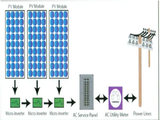
Fig. 1 represents a generalized block schematic of Renewable based AC micro grid. Solar panel array is suitable to be used as a generating source in micro grid as it has several advantages over other WTG topologies. WTG is based on win speed. Then the wind speed is not constant so we pleased the variable speed control mechanism. But solar panel array is not required that on so this is suitable for generate AC micro grid system
Fig. 1: Block schematic of AC micro grid
• The AC micro grid must be reliable. Power supply quality should be maintained to a suitable level.
• The AC micro grid must be utilized to small scale industries.
• The AC micro grid solar energy must be stable. It should be able to sustain dynamic load conditions and variation in generating power due to intermittent nature of wind energy.
• The system should have least maintenance requirement and minimum cost of installation.
• The AC micro grid should be able to adapt changes even after initial sizing and installation. These may be changes in storage or generation capacity, and changes in the load pattern.
III. NEED FOR ENERGY MANAGEMENT
Energy management for AC micro grid has several significant roles:
• Reliability: providing uninterrupted supply to the load.
• Quality: maintaining quality of supply.
• Stability: maintaining AC-link voltage constant.
• Maximum utilization of generating by sources
• Efficient management to loads.
Sizing of generating sources and Quality power transition is a prime concern while designing any isolated system, since the load demand should be met completely by generating sources and the ESS, without grid intervention. In spite of this, sizing is not the fundamental requirement of the micro grid presented here. The micro grid would be able to adapt changes for quality power transition. Photovoltaic panel would play a primary role of supplying voltage to the system. This is also essential with compare to wind turbine generator.
Hear we use STATCOM for remove non linearity’s from load current. In stat com we use buffer circuit for identify the remove non linearity’s from load current.
IV. SIMULATION OF AC MICROGRID
An isolated AC micro grid has been designed and validated using MATLAB/SIMULINK. It consists of four main parts: generating sources, STATCOM, loads and energy management system.
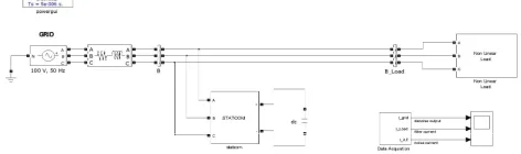
Fig. 2: Circuit diagram for energy management for AC micro grid
Fig. 2 shows the basic line diagram for this line diagram for energy management for AC micro grid system. In the circuit diagram we identify the block diagram of STATCOM, nonlinear load and another block for data acquisition. This block use to find the differences between load current, filter current and de-noise output like grid current.
i. PI Controller ii. Buffer amplifier
iii. Power management system
From solar panel we tack the source power. We are design for 100 V power to the 3Phase series RL circuit for filter input given to the circuit this is fist stage of filtration. From hear we give the input to linear load and nonlinear load for finding the current wave forms to filter stage by stage.
First we tack nonlinear load to analyze the input power. Hear we connected the R-L load to the circuit. RL loads are the linear Components. For these elements we required linear load for good working condition. So we use 6 stages of filters for the removing nonlinearities from the input signal. It is shown in Fig.3in the current wave form we find the difference between the filtered nonlinear signal and non linear signal. Before the filtration the noise level is more in the input signal. Then we apply the 6-stage of filtration so that the noise level will be decreased from the non linear input signal.
Now we decease about the linear loads we connect the STATCOM to analyze the power in line current. In the STATCOM we connect pi-controller, buffer, instantaneous power generator, compensating current circuit, Pulse generator and inverter with coupling inductor.
Vabc= 3-Phase voltage equations for instantaneous power generator. Iabc= 3-Phase current equation for instantaneous power generator. PSOC = power output source current.
I_comp = compensating current. Ic_Pi = input current and pi-controller.
Hear we give dc in put to the pi controller for good working conditions. For PSOC we give summation input to the compensating current circuit. The adder {++-} have 3 inputs first one is pi controller out put second one is buffered out put and third one is instantaneous power from Vabc and Iabc.
From the instantaneous power we connect the 3 lines to the compensating current block. First one is the 3-Phase power, second one is reactive power. Before compensating the line current we apply the buffer circuit. This one is one of the main connections in the circuit .before connecting the buffer and after connecting the buffer circuit the wave form is shown in the fig 4. it will be give a way to first in put signal and up to until first signal complete the operation remaining input signals will be hold on buffer. When the first signal completes then the second input signal come to operation. In this process we find the before buffered and after buffered signal.
Fig4. {A} current wave form for linear loads
Then the compensating current device gives an input signal to the inverter through the pulse generator. Hear the pulse generator will measure the number of pulses given to the inverter. This is use full to find the operation time of the circuit. The inverter will operate with the dc power. Because inverter operation is converts dc power to ac power. So we give dc power to the inverter V_dc.the out put of the inverter will be connected to coupling inductor. It will help to the circuit and save from over load condition. The circuit main intension is to filter the load current in different stages and give distortion less current to the loads.
V. CONCLUSION
The paper reviews limitations of conventional DC power grid and presents renewable based AC micro grid as an optimum solution for fulfilling energy requirement. This paper proposes adaptable renewable based AC micro grid with energy management system.
Fig3. {A} wave form for grid current. {B} wave form for load current. {C} wave form for Filter current.
In the transmission the power will effected by the noise level and distortion effect. So we remove the noise level in the circuit with help of the filter and distortion will be removed with the help of the buffer circuit and compensating circuit. In present days we all are more familiar with the electronic equipments. These electronic equipments are working with dc power. So we include inverter for dc lodes. Finally we will give filtered current to loads.
REFERENCES
[1] Ishwari Tank ,Renewable Based AC Micro grid with Energy Management System , IEEE 2015
[2] Shrikant Mali,Renewable Based AC Micro grid with Energy Management System , IEEE 2015
[3] R. Singh and K. Shenai, “Dc microgrids and the virtues of local electricity,” in IEEE Spectrum, 2014.
[4] S. Mali, S. James, and I. Tank, “Lvrt for wind power system,” in International Conference on Advances in Energy Research, 2013.
[5] T. Ersal, C. Ahn, D. L. Peters, J. W. Whitefoot, A. R. Mechtenberg, I. A. Hiskens, H. Peng, A. G. Stefanopoulou, P. Y. Papalambros, and J. L.
Stein, “Coupling between component sizing and regulation capability in microgrids,” IEEE Transactions on Smart Grid, vol. 4, no. 3, 2013.
[6] B. K. Bose, Modern Power Electronics and AC Drives. PHI Learning Pvt. Ltd., 2013.
[7] S. S. Mali and B. E. Kushare, “Mppt algorithms: Extracting maximum power from wind turbines,” International Journal of Innovative Re-search in Electrical, Electronics, Instrumentation and Control Engi-neering, 2013.
[8] ND-A215A2, Sharp Corporation of Australia Pty. Ltd.
[9] O. BA, D. DEPERNET, P. A. NDIAYE, and A. BERTHON, “Di-chotomic algorithm to drive a wind mill in association with pv panels for
stand alone electrical energy production,” in EPE ’09. 13th EuropeanConference on Power Electronics and Applications, 2009.
[10] S. N. Chaphekar, V. V. Khatavkar, and A. A. Apte, “Cogeneration an emerging trend in india for energy crisis,” in IEEE International Conference on Industrial Technology, ICIT 2006., 2006.
[11] M. O. Haruni, M. Negnevitsky, M. E. Haque, and A. Gargoom, “A novel operation and control strategy for a standalone hybrid renewable
power system,” IEEE Transactions on Sustainable Energy, vol. 4, no. 2, 2013.
[12] N. Bhende, S. Mishra, and S. G. Malla, “Permanent magnet synchronous generator-based standalone wind energy supply system,” IEEE