Abstract—In this paper, the design, implementation and
experimental results of an effective data communication protocol implemented on a distributed PIC microcontroller architecture based Automated Guided Vehicle (AGV) named ROVER II (Roaming Vehicle for Entity Relocation) is presented. The main objective of the research was to design and implement a seven-bit speed control signal for ROVER II’s speed and position control allowing for one percent duty cycle increment.
Index Terms—Mobile robot, speed/position control, data packets, encapsulation/ decapsulation, Pulse Width Modulation (PWM).
I. INTRODUCTION
Recently, many studies have focused on the development of AGV’s [1] and [2] and the area of mobile robotic has become a very active topic of research. This is fueled by recent advances in microprocessor and sensor technologies and the potential applications offered to the manufacturing and service industries by mobile robotic systems [3]. A typical application within manufacturing environment is an AGV which is a driverless vehicle that performs material handling transportation within a facility [4]. Despite the various problems associated with the installation and maintenance of AGV systems [2], they find wide applications in warehousing, assembly and transfer of tool drums and in factories in general [5], in nuclear plants [6], in household use [7] and indoor security application [8], to mention a few.
Borenstein and Koren [7] designed an indoor nursing robotic system whose control system, based on the principle of a cross-coupling controller, measures the difference in the speed of the two motors used for locomotion. Based on this difference in speeds, the control system increases the speed of the slower motor and then decreases the speed of the faster motor at the same time. Thus, the corrected value of speed depends upon the errors in the speeds of both motors.
For the past few years, the School of Engineering and Physics (SEP) at the University of the South Pacific (USP) have been conducting research on the use of mobile robots
Manuscript submitted for review on November 29, 2010.
Shiu Kumar is now with the Department of Electrical & Electronics Engineering of Fiji National University, Suva, Fiji Islands. (phone: +679 9439438; e-mail: [email protected]).
Ravinesh Singh is with the School of Engineering, University of The South Pacific, Suva, Fiji Islands. (e-mail: [email protected]).
used in manufacturing facilities [2]. The present paper presents the outcome of the study on providing improved solution to the design and implementation of robust motion controller for the guide-path following mobile vehicles, customized for material handling transportation within a manufacturing facility, namely ROVER I & II designed in-house [1] .The proposed advanced speed control architecture highlighted in this paper will improve ROVER II’s drive system, which proposes to use seven bits of data for speed control allowing for duty cycle to be incremented at one percent duty cycle compared to three bit speed control data with only seven possible distinct duty cycles [1].
This paper is organized as follows. The second section of the paper gives an overview of related works that has been carried out. Section III introduces ROVER II and its existing Star distributed architecture, hardware framework, and speed control architecture. In sections IV-VI, the newly proposed advanced speed control architecture is provided. Section VII discusses about the different tests that has been carried out. A general conclusion ends the paper and presents some perspectives.
II. RELATEDWORKS
The first application to robotics appears in the 90’s with the works of R. Brooks inspired from ant’s colonies [9] and [10]. He proposed several architectures based on reactive behaviors and machine learning. Recently, many studies have focused on the development of an effective speed control for robotics drive system [2].
To mention a few, firstly the Sliding mode control of an induction motor [11]. In this project Field-oriented control (FOC) was combined to robust sliding mode for motor speed control and a smooth continuous function was added in order to overcome chattering caused by Sliding Mode Controller (SMC). The SMC mode does not require an accurate model of the motor, which might necessitate only information on parameters value.
The Fuzzy Logic Control for Speed Control of Induction Motor using Space Vector Pulse Width Modulation [12]. It presents the design and implementation of a voltage source inverter type space vector pulse width modulation (SVPWM) for controlling the speed of induction motor. This scheme led to adjust the speed of the motor by controlling the frequency and amplitude of the stator voltage, while the ratio of stator voltage to frequency was kept constant.
Advanced Speed Control of an Automated
Guided Vehicle
The Mobile robotic platform controller with an effective data communication protocol [2] has also been implemented. The control system was designed for the drive wheels of robot, namely ROVER III designed in-house, for independently controlling closed-loop motion of each robotic wheel without the inclusion of a line tracer sensor unit on the robot. For this reason, only components essential to the design and implementation of the control system were used on the robotic platform. The robotic motion control model designed in this project takes into account the turning motion, by keeping the control system of one wheel completely independent of the other wheel. The errors in the speeds of each wheel are corrected to the value of the input speed command of each wheel. Errors from the difference in the two wheel speeds are not compared, neither are they cross-coupled as done in the project of Borenstein and Koren [7].
Distributed PIC Microcontroller Architecture for AGV Application [1] has also been designed. This project deals with multi-objective task that is getting path data information, obstacle and station detection, line and node tracing, battery voltage monitoring, and speed and position control with feedback controlled by five PIC16F877 microcontrollers arranged in a Star distributed architecture. Due to the limited number of pins available on the motor co-controller PIC16F877 boot loader board, only three-bit speed control signal was used to control the speed and position of ROVER II. Since ROVER II deals with travelling along complex guide path using line tracing sensors, a more advanced speed controller was required and hence speed control architecture similar to ROVER III’s drive system [2] has been adopted.
III. DESIGNOFTHEMOBILEROBOT
This section details the design of the distributed Peripheral Interface Controller (PIC) microcontroller-based AGV at the University of the South Pacific, which is referred to as ROVER II. ROVER II has been designed in-house with application of five PIC16F877 microcontrollers arranged in a Star distributed architecture. Four of these microcontrollers are dedicated as co-controllers for motor speed/position control, sensor control, power supply control and keypad/liquid crystal display (LCD) control while the fifth PIC microcontroller, which is the master controller, overlooks and coordinates the functionality of the four co-controllers.
A. Operation of the AGV
The AGV (ROVER II) which has been developed is
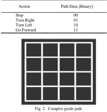
capable of following any predefined route of a complex guide path for material handling and transportation within a manufacturing system. The user firstly has to provide user authentication by the verification of password followed by specifying and uploading a particular path data using the keypad and LCD module, which is then transferred and stored on the master controller. Table I shows the respective two bit logic path data coordinates that needs to be appropriately entered by the user depending on the path actions while Figure 2 shows the complex guide path. The master controller uses this path data to control the co-PIC motor controller to follow the predefined route by appropriately varying the speeds of the two 12V, DM08GN direct current (DC) motors.
The left and right line tracing sensors controlled by the sensor co-controllers are used to keep the AGV on track and additional front and side infra red (IR) ranging sensors are used to detect obstacles and stations respectively. As the stations are detected the AGV stops for 5seconds to load/offload materials using the conveyor unit. Whereas, if the obstacles are detected, the AGV stops until the obstacles are removed from the front of the sensors. In both these cases, whenever the AGV restarts after stopping, it remembers the operation which it was performing before being interrupted to stop and hence continues performing the same task which it was doing before stopping. As a result, ROVER II has memory capability to remember the task that it was performing before stopping and recalls this when it resumes operation. The co-PIC sensor controller reads in all this sensor input as hardware interrupt inputs and hence generates interrupt signals as either of these sensors is activated.
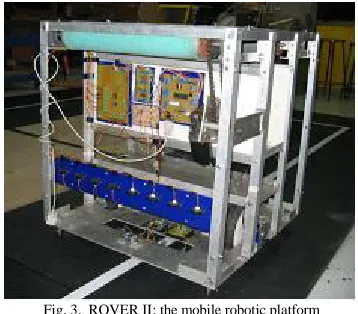
[image:2.612.330.517.235.430.2]A power management co-PIC power supply controller is also incorporated which automatically swaps the AGV’s supply battery with a backup battery, once the voltage of the supply battery falls below a specified threshold. Figure 3 shows the mobile robotic platform.
Fig. 1. ROVER II’s distributed Star microcontroller architecture
Fig. 2. Complex guide path TABLEI
BINARY REPRESENTATION OF ROVERII’S PATH ACTIONS.
Action Path Data [Binary]
Stop Turn Right Turn Left Go Forward
[image:2.612.77.292.600.684.2]B. Speed Control architecture of ROVER II
The PWM signal supplied by PIC16F877 to the Universal PWM H-bridge motor driver circuits has been used to drive the DM08GN, 12V drive wheel motors of the robot. Due to limited number of input pins available, three-bit input control signals generated by Master controller were used to generate eight distinct duty cycles as shown in Table II.
These duty cycle combinations were easily generated using equation 1, with a special condition applied to generate zero percent duty cycle when three-bit inputs are [000]. The Master controller provides two separate PWM control signals for the left and right DC motors.
% Duty Cycle = [(3-Bit Input) * 6.25] + 50 (1) IV. CONTROLSYSTEMDESIGN
The control system was designed for the drive wheels of the robot. The main objective of the research was to design and implement a seven-bit speed control for the robotic wheel with the line tracing sensor unit on the robot, allowing for duty cycles to be incremented at one percent.
Complete single control system allows sending of two different input speeds to each of the drive wheels. Errors from the difference in the two wheel speeds are compared and corrected to the value of the reference wheel speed.
A. Hardware control system
The proposed three wire bus, n-bit serial latched communication system used in the mobile robotic platform controller is shown in Figure 4, while a block diagram showing the data flow between Master controller and motor co-controller of the robotic platform is presented in Figure 5.
The system had to be designed such that the robotic platform would be able to follow any predefined route of a complex guide path as shown in Figure 2, for material handling and transportation within a manufacturing system. The system has a controller for the purpose of issuing the speed and direction commands.
The system input speed supplied by the Master controller is acted upon by the motor co-controller, which then generates appropriate PWM signals with duty cycle equal to the input speed. After each revolution of the reference drive wheel, the difference in wheel speeds is calculated with respect to the feedback received and the duty cycle of the non-reference motor is either incremented or decremented depending on whether the non-reference motor is slower or faster respectively.
B. Electronics Design
The mobile robot has two DM08GN, 12V Tunglee permanent magnet DC motors with a shaft encoder disk each, two photo-transistor/emitter diode pair sensor boards, ten Sharp infra red sensors, five Lynx motion sensors, power supply control boards, sensor control boards, keypad and LCD board, two H-bride motor controller boards and five PIC16F877 bootlaoder boards designed in-house. The electronic design of ROVER II which is fully described elsewhere [1] and hence is not covered here.
[image:3.612.94.273.46.203.2]PWM scheme with fixed frequency and varying duty cycle was used to control the DC motors since it makes implementation easier compared with the use of adjusting inductance of motor windings, changing the stator voltage, and adjusting the supply frequency [13]. The two H-bridge motor driver boards designed in house has an extra circuit consisting of AND and NOT gates as shown in Fig. 6. Due to only one PIC motor co-controller board used to drive both the drive wheels and the fact that PIC16F877 bootloader board has only two PWM pins (C1 and C2), this
Fig. 3. ROVER II: the mobile robotic platform
Fig. 5. The mobile robotic platform speed controller of the robotic platform hardware.
Fig. 4. The propose three-wire bus, n-bit serial latched communication system used in the mobile robotic platform controller
TABLEII
THREE BIT CONTROL SIGNALS AND ITS CORRESPONDING DUTY CYCLE
Decimal Equivalent 3-Bit Input Duty Cycle (%)
0 1 2 3 4 5 6 7
000 001 010 011 100 101 110 111
[image:3.612.348.505.46.98.2] [image:3.612.316.541.130.279.2]circuit was designed to allow driving the motors in both clockwise and anti-clockwise directions using only one PWM signal.
V. DATA COMMUNICATION DESIGN
The earlier version of the mobile robotic platform controller which has similar architecture as the current one as shown in Fig. 4 consists of a Master controller and one motor co-controller for controlling both wheels and the peripheral hardware, except that it was designated to issue two separate three-bit speed command for each motor. The three-bit command architecture falls short and needs to be replaced since only seven (23-1) speeds were possible with this architecture and hence was not adequate for each motor. For such medium to high-speed applications, the concept of encapsulation/decapsulation in which the speed is serially transmitted as a packet in binary equivalence solves the problem.
In this section, the features utilized for developing the three-wire bus, n-bit serial latched data communication system for controlling the robotic wheel are discussed. These features consist of packets, encapsulation and decapsulation.
A. Packets
Today’s internet technology is an offshoot of the ARPAnet developed by Advanced Research Projects Agency (ARPA) of the US Department of Defense [14]. One of the primary goals of ARPA for the networking was to allow multiple users to send and receive information simultaneously over the same communication path such as telephone lines. Since the success of ARPA in introducing packets for data communication, the concept of packet has become commonly used in data abstraction, mainly in computing science and communication engineering (see for example, [14] and [15]). Associated with packets, are techniques of encapsulation, decapsulation, encryption, and decryption. While encryption and decryption are mainly reserved for security issues in data communication, encapsulation and decapsulation are merely the ways of encoding and decoding data that are transmitted.
The packet used in the research reported in this article has a length of 14-bits, although limiting the size to a fixed number is not necessary because it is under the control of the systems designer to specify other length of bits, and in general, n-bits could be used. The 14-bits are divided into two sections, the first 7-bits from bit 0 to bit 6 are used to capture the left motor speed while the second set of seven bits from bit 7 to bit 13 are used to capture the right motor speed. The maximum possible speed that can be encapsulated into a packet is 127 (27-1). Robotic applications require very low speeds, hence the architecture
presented in the present paper meets the requirements of a wide cross-section of engineering applications ranging from low, medium and high speeds.
The Robotic and Automation Group (RAG) at The University of the South Pacific is utilizing the three-wire bus, n-bit serial latched data communication system for controlling a milling motor that has maximum speed of 1800 r/min and three stepper motors in a milling machine being developed in-house [16]. In practice, only maximum of 9–10 lines would be required to transfer milling speeds in parallel mode. Figure 7 shows the packet layout used for the research reported in this article.
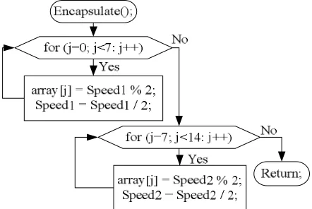
B. Encapsulation
The process of encapsulation (encoding) takes place at the Master controller and involves converting the speed data into a packet for the purpose of transmission. The method used in realizing encapsulation is that of conversion of the decimal number to its binary equivalence that are bundled into the packet as shown in Figure 8.
C. Decapsulation
Decapsulation (decoding) commences at the motor co-controller once the packets are received as shown in Figure 9.
[image:4.612.321.542.366.514.2]PWM DIR
Fig. 6. AND and NOT gate circuit on the H-bridge motor driver circuit.
Fig. 7. Packet Layout
Fig. 8. Mater controller’s encapsulation sub-routine
Fig. 9. Motor co-controller’s decapsulation sub-routine
[image:4.612.317.540.589.720.2]D. Method of Transmission from Master Controller Bootloader Board
Since the data being transmitted are the entire packet, they need to be first converted into a binary format, one bit at a time and sent from the Master controller to the motor co-controller.
There is a sequence to follow for PIC bootloader to transmit data accurately. Firstly, PIC bootloader has to be in the latch enable or data receive mode. Secondly, the clock has to be high to make PIC bootloader ready to read a bit of data being sent and finally, when the data are completely sent, the clock is made low and the latch is disabled. From experimentation, some amount of delay would be needed after the clock has been made low. Figure 10, which is self-explanatory, shows the timing requirements and specification for the data communication sequence.
E. Method of reception on Motor Co-controller Bootlaoder Board
The motor co-controller only receives data if it is in the latch enable or data receive mode. Secondly, the clock has to be high. Once the data is available at the input, the clock has to be low in order for the motor co-controller to read the input. The latch is disabled and decapsulation commences once the motor co-controller successfully receives the serial data that the master PIC bootloader sent.
F. Merits of the current data communication protocol
An earlier version of the communication used six lines, three per each motor speed for motor co-controller from the Master controller. The current three-wire bus therefore presents a significant saving in communication. It frees three lines from the Master controller, which could later be used for other applications and also the present three-wire bus communication protocol significantly expands the range of speeds attainable. For example, the three-line protocol is limited to maximum of seven possible speeds whereas the three-wire bus communication protocol caters for up to 127 possible speeds.
VI. SOFTWARE DESIGN
The software was designed in such a way so as to enable a standard pattern of operation. The software coding for this project was done in PIC C compiler, a standard compiler for PIC microcontroller. Even when all the separate hardware is connected together, the unity among the components and the wholeness of the system is only achieved through software implementation. The Master controller uses two types of interrupts: Timer 0 interrupt
and Port B interrupt while the motor co-controller only uses Port B interrupt.
The Master controller starts of by going through an initialization process. Here all the pins on Port E together with all the output pins on Port D are first set to zero. Since Port E pins E0 to E3 are used to send the speed control signals to the motor co-controller inputs, resetting these ports make sure that the speed communication latch is disabled. Resetting Port D pin D6 disables the interrupt signal to the keypad and LCD co-controller and pins D0 and D1 sends logic zero signals to the direction control of the Universal PWM H-bridge motor driver circuits. Next the Empty_Array() subroutine is called which sets the content of the path data to zero. After this, the master controller calls the Communication_Link() subroutine function which enables interrupt RB (INT_RB) and disables all other interrupts and at this time master controller sits idle waiting for the user to enter the required authentication and path data. Once the user has entered the path data, master controller checks if any station or obstacle is detected and then sends the appropriate speed control signals to motor co-controller.
The motor co-controller commences by setting pins C1 and C2 as PWM pins and then disabling the two motors by sending logic high to the two Universal PWM H-bridge motor driver boards. It then enables the Port B interrupts and waits for the command from master. Upon receiving the speed command, it then enables or disables the H-bridge motor driver boards and generates the appropriate PWM signals. It then determines whether the state of pins B4 and B7 has changed by comparing the present and past states of the two pins. Whenever there is a change, the respective two counters are incremented signifying the motor encoder disk has rotated. The motor co-controller then checks whether the two motor input speeds from master are same or not. If the input speeds are same, then depending on the speed feedback from the two encoders, the duty cycle of the non-reference motor is either incremented or decremented depending on whether the non-reference motor is slower or faster with respect to the reference motor.
The resolution of the vehicle is given by equation 2, where NS, rwheel are the number of encoder slots and the radius of the vehicle wheel respectively. For ROVER II, NS = 32 and rwheel = 100 mm therefore the resolution is given as:
Rres = S
N
wheel
r
π
2
=
32
(0.1)
2
= 0.0196 m (2) The number of pulses required for any distance can be calculated using equation 3, where Rres, x are the resolution of the encoder and the distance that the vehicle travels respectively. Hence, the number of pulses required for ROVER II to travel 1m is:
Npulses = res
R
x
=
0196
.
0
1
= 51 pulses (3)
VII. EXPERIMENTALRESULTS
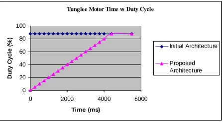
The speed/duty cycle versus time was carried out. A program was incorporated within the initial and the proposed speed control to print the duty cycle of the drive wheels at certain intervals. An interval of 20ms with duty cycle increasing by one percent at every interval was chosen since it gave a smooth start to the mobile robot without any jerks and also the desired speed was obtained in less than two seconds. This data was collected and the respective graphs were plotted as shown in Figure 11.
With the proposed architecture, the mobile robot now starts by increasing its duty cycle slowly at one percent increment every 20ms and once it reaches its desired speed, it then moves with the desired constant speed as shown in Figure 11. This new architecture allows mobile robot to move as in real life. For the 3-line architecture with only seven possible speeds for moving the mobile robot and the change in duty cycle from one speed to the other actually took place by jerking the mobile robot to the desired speed. This is shown in Figure 11 for the initial architecture where the mobile robot starts from rest to go forward at 88 percent duty cycle.
A delay of 20ms was used for this application. For other applications, depending on the robotic platform the time to reach its desired speed can easily be specified by the designer by appropriately changing the delay between each increment.
The slope for the proposed architecture of Figure 11 is the acceleration rate of the mobile robot and is calculated to be 0.05. Since speed is directly proportional to duty cycle, we can conclude that the mobile robot will increase speed with a slope of 0.05.
VIII. CONCLUSION
This paper presents the design, implementation and experimental results of an effective data communication protocol implemented on a distributed PIC microcontroller architecture based AGV named ROVER II. In a robot, the three-line data communication protocol restricts the control on the speed of the wheel, see for example [1], where only eight distinct duty cycles were possible and any change in speed will occur in jerks. The work done shows that the proposed three-wire bus, n-bit serial latched data communication protocol for controlling the motion of the robotic wheel with the line tracer sensor unit on the robot,
is by far more effective than the three-line data communication protocol used in an earlier architecture as discussed in section V(F). The proposed architecture also allows for ramping of speeds as in real life situations as discussed in section VII.
REFERENCES
[1] R. Singh, “A Distributed PIC Microcontroller Architecture for AGV Application,” MSc thesis, University of the South Pacific, Suva, Fiji, 2006.
[2] G. C. Onwubolu, I. Jannif, M. Tazil, and A. Singh, “Mobile robotic platform controller with an effective data communication protocol,” Journal of Engineering Manufacturer-Proceedings Part B, Vol 220, pp. 1175-1188, 2006.
[3] J. Mallon, O. Ghita, and P. F. Whelan, “An Integrated Design Towards the Implementation of an Autonomous Mobile Robot,” in Proc. of the Eight International Conference on Optimization of Electrical and
ElectronicEquipment, Brasov, Romania, 2002.
[4] B. Sarker, and E. Hoff, “An overview of path design and dispatching methods for automated guided vehicles,” Integrated Manufacturing Systems, 9(5):296-307, 1998.
[5] R. C. Dorf, “Robotics and automated manufacturing,” 1983a (Prentice-Hall, Reston).
[6] C. Weisbin, G. Saussure, and D. Kammer, “Selfcontrolled, a real-time expert system for autonomous mobile robot,” Computers in Mech. Eng., 1986, 12–19.
[7] J. Borenstein and Y. Koren, “Motion control analysis of a mobile robot,” Trans. ASME, J. Dynamics, Msmnt Control, 1986, 109(2), 73– 79.
[8] D. Carnegie, D. L. Loughnane, and S. A. Hurd, “The design of a mobile autonomous robot for indoor security applications,” in Proc. Instn. Mech. Engrs, Part B: J. Engineering Manufacture, 2004, 218(B5), 533–543.
[9] R. A. Brooks, “A robust layered control system for a mobile robot,” IEEE Journal of Robotics and Automation, p. 14-23, 1986.
[10] R. A. Brooks, “New Approaches to Robotics,” Artificial Intelligence Laboratory, Massachusetts Institute of Technology, Cambridge, MA 02139.
[11] K. Jamoussi, M. Ouali, and H. Charradi, “A Sliding Mode Speed Control of an Induction Motor,” American Journal of Applied Sciences, 4(12): pg 987-994, 2007.
[12] S. Tunyasrirut, T. Suksri, and S. Srilad, “Fuzzy Logic Control for a Speed Control of Induction Motor using Space Vector Pulse Width Modulation,” World Academy of Science, Engineering and Technology 25, 2007.
[13] M. A. El-Sharkawi, “Fundamentals of electric drives (Brooks/Cole, Belmont, CA),” 2000.
[14] H. M. Dietel, “Cþþhow to program,” Prentice Hall, New Jersey, 2001. [15] J. C. Campbell, “Programmer’s Guide to Serial Communications,” 2nd
edition, 1994, pp. 98–100, (SAMS, Indianapolis, IA).
[16] I. N. Jannif, “Development of a CNC Milling Machine,” Unpublished Postgraduate Project Report, University of the South Pacific, Fiji, 2005.
BIBLIOGRAPHY Tunglee Motor Time vs Duty Cycle
0 20 40 60 80 100
0 2000 4000 6000 Time (ms)
D
u
ty
C
y
c
le
(
%
)
Initial Architecture
[image:6.612.68.292.172.295.2]Proposed Architecture
Fig. 11. The mobile robot’s speed versus time with the initial and proposed architecture
Ravinesh Singh is with the School of
Engineering and Physics, University of The South Pacific, Suva, Fiji. His area of research and teaching interest includes microprocessors and robotics.
Shiu Kumar received his Bachelor’s Degree in