ISSN 2348 – 7968
Analysis of Different Hall Effect Current Sensors for Space
Applications
Arya Krishna S.P
1
P
, Lizy AbrahamP
2
P
P
1
P
PG Student, Department of Electronics and Communication Engineering, LBSITW, Trivandrum, Kerala, India
P
2
P
Department of Electronics and Communication Engineering, LBSITW, Trivandrum, Kerala, India
Abstract
Current sensing is one of the most important functions in power electronic applications and space applications such as different power consuming modules of a spacecraft subsystem. In conventional current-sensing methods a resistor is inserted in the path of the current to be sensed. This method incurs significant power losses, especially when the current to be sensed is high. Hall Effect current sensors provide lossless and isolated current-sensing solution, by current-sensing the current without dissipating the power that passive resistors do.This work focuses on analysing the performance characteristics of few new types of Hall Effect current sensors available today. Also a comparative analysis is done by comparing the performance of certain new current sensors against the performance of the current sensor that is currently being used in satellite systems. The objective of such an analysis is to determine if the newly available Hall Effect current sensors could give better performance than the presently used one, so that it could be replaced for deriving performance and cost benefits. The performance characteristics are plotted and viewed in LabVIEW platform.
Keywords: 33THall Effect, Sensitivity, Programmable Electronic
Load, Offset.
1. Introduction
A current sensor is a device that detects and converts current to an easily measured output voltage, which is proportional to the current through the measured path.It is an economical and reliable tool that is indispensable for monitoring equipment status, detecting process variations, and ensuring personnel and device safety. There are two types of current sensing: direct and indirect. Direct type of current sensing is purely based on Ohm’s law. By placing a shunt resistor in series with the system load, a voltage is generated across the shunt resistor that is proportional to the system load current. This method is an invasive measurement of the current since the shunt resistor and sensing circuitry are electrically connected to the monitored system. Therefore, direct sensing typically is used when galvanic isolation is not required.
Indirect current sensing is based on Ampere’s and Faraday’s laws. Hall Effect sensing is an indirect current sensing technology based on the principle that for a given current flow, a proportional magnetic field is produced around the current-carrying conductor. A Hall Effect sensor measures the strength of this magnetic field from a
nearby conductor and determines the magnitude of the current passing through a conductor. Thus Hall-effect technology allows for contactless sensing devoid of mechanical wear and is best suited for measuring DC current.
For space applications current measurements are required in various situations. For example continuous current monitoring is required in high current ignition method of hybrid rocket motors which involves passing a high current through a resistance wrapped around a plastic fill tube, in an oxygen rich environment to ignite the fuel and oxidiser. Also current sensing is important in different power consuming sensor modules and motor control units of spacecraft subsystems for current based fault detection and circuit-protection. The current sensor that is currently being used for these applications, for current measurements from few tens of Amperes to 100 Amperes is LT 100-P, manufactured by LEM.
In this work the performance of LT 100-P is compared against two new types of Hall Effect current sensors available today. In any transducer development process a full regimen of tests will be carried out comprising the characterization report and these results will be specified in the datasheet. However, these tests follow the scientific method, varying individual parameters to characterize the transducers response to each. In the actual application, several factors can act simultaneously and potentially provide unexpected results. Hence it is essential to assess the transducer in those conditions to verify acceptable performance and check if the performance is accurate and reliable as specified in the sensor datasheet. Therefore in the proposed method analyses of few new types of current sensors are done and results are plotted in Lab VIEW platform.
2. Hall Effect Sensor -Working
ISSN 2348 – 7968 an output voltage proportional to the
magnetic field strength. The voltage output is usually very small in the range of microvolts and requires additional electronics to achieve useful output levels.
When the Hall element is combined with the associated electronics, it forms a Hall Effect sensor. The heart of every Hall Effect device is the integrated circuit chip that contains the Hall element and the signal conditioning circuitry.
Figure 1 shows the block diagram of a sensing device using the Hall Effect. In this generalized sensing device, the Hall sensor senses the field produced by the magnetic system. The magnetic system responds to the physical quantity to be sensed (in this case current) through the input interface. The output interface converts the electrical signal from the Hall sensor to a signal that meets the requirements of the application. Hall Effect sensors can be classified into three types-open loop, closed loop and linear Hall Effect sensors.
Fig 1: General Sensor Block diagram based on the Hall Effect
3. Sensors Selected for Analysis
The paper proposed by Ljubomir [1] compares operating characteristics of nonconventional current sensors, Rogowski Coils, and conventional iron-core current transformers for protective relaying applications. Here the analysis included search for characteristics like high measurement accuracy and a wide operating current range that could allow the use of the same device for both metering and protection. A New Hybrid Current Sensor that combines a Rogowski coil, a passive integrator, and an IOPC (integrated-optic Pockels cell) with sufficient sensitivity was proposed by Jeffrey D. Bull et al [2] for High-Voltage Applications. This sensor showed excellent linearity, but its size was larger making it unsuitable for space applications. A Novel Isolated Current Sensor proposed by N. Karrer et al. [3] registered an excellent
linear behaviour up to 40 A DC but showed drastic variations in linearity and stability with temperature variations. The paper published by Quentin L. Willard et al. [4] listed the key concerns while selecting a sensor for use in space applications. Some of the key concerns included weight, size, radiation, power and power sources vibration, cost visibility, thermal capability etc. Considering these entire facts, two new Hall effect sensors, FHS 40-P and AH 3503 were selected.
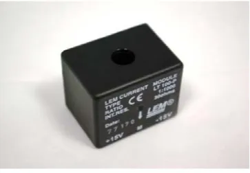
Fig 2: LT 100-P
The Hall Effect sensor that is currently being used for current measurements from few amperes to 50A, in satellite subsystems is LT 100-P, which is a closed loop Hall Effect sensor, manufactured by LEM. AH 3503 manufactured by Nanjing AH Electronic Science & Technology and FHS 40-P manufactured by LEM are the two other sensors selected for analysis. These sensors were selected based on their typical features as mentioned in the datasheet, which makes them suitable for space applications. Some important criteria for selection included light weight, fast response, losslessnes, high sensitivity and excellent linearity over wide range of operating temperatures
Fig 3: AH 3503 Fig 4: FHS 40-P
4. Test Setup
ISSN 2348 – 7968 current mode, to simulate real load
conditions. This setup can be used for battery discharge analysis also. The electronic load is programmable and is programmed using Visual Basic. Figure 5 shows the block diagram of the basic test setup for current sensor analysis.
Fig 5: Test Setup
The battery source is connected to the electronic load via the current sensor. The battery source used was a Silver-Zinc battery of 6V, 10Ah rating. The load is in constant current mode, i.e. the 33501 series electronic load will sink a current in accordance with the programmed value. The current drawn by the 31Tbattery31T is sensed by the current sensor. The current sensor output is displayed in DSO.
The oscilloscope used was the DL750 series model DSO manufactured by Yokogawa. This DSO has got many beneficial features like high accuracy, fast signal acquisition and TFT liquid crystal display that offers good display resolution. Hence the DSO output obtained will be highly precise and accurate. It can be saved in .csv or .wvf format and can be further processed and plotted in LabVIEW.
Readings were taken in two ways. First set of readings were taken by setting a constant current sink value in the electronic load and measuring the output voltage sensed by the current sensor. But when high current (greater than 50A) is sinked by the electronic load continuously, there occurred sudden dip in the battery source. Hence only upto 50A constant readings were taken in this way. To avoid this sudden battery dip, current sinked by the load was configured as short current pulses with 100ms on time and 200ms off time. This kind of configuration, to draw different current inputs in the form of a pulse, is possible by programming the electronic load using Visual Basic code.
5. Results and Inferences
For each of the current sensors the outputs were obtained and saved in DSO as .csv files. These files were read in LabVIEW. For Hall Effect sensors sensitivity is a function of distance from the primary circuit. Since all the three sensors selected were Hall Effect based test results were obtained in such a way that the sensors are kept at a distance which is most suitable for providing its maximum sensitivity.
The input current versus output voltage plots, sensitivity and offset voltage values were then obtained in LabVIEW. These readings were compared for all the three current sensors selected for analysis and inferences are drawn.
5.1 Analysis of LT 100-P
LT 100-P is a closed loop current transducer using the Hall Effect. Its typical supply voltage is +15V and -15 V. The voltage output is taken across a resistor (RRMR) of value ranging from 30 to 85 ohm as shown in figure 6. In order to avoid saturation at high current inputs (above 100 A), 50 ohm resistor is used at the output. In the analysis, input currents varying from 10 A to 150 A were given in the form of short pulses.
Figure 6: LT 100-P connection diagram
LT 100-P sensor output provides a scaling in the ratio 1:1000.i.e if the current flow through the original primary circuit is 1A then the sensor generates a current of 1 mA and since the output is taken across a 50 ohm resistor it reads 50mV at the output.
According to datasheet LT 100-P has got the following specifications. Its maximum nominal current value which provides a linear output is 100 A at 25ºC. Its offset output voltage value = 0 V @ 25ºC. Offset value is the output obtained when no current flows through the primary and the sensor is supplied with its normal supply voltage.
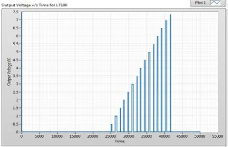
For analysis the input current was given as 10A, 20A and so on upto 150A current pulses. The output voltage v/s time , output current v/s time, offset voltage and output current v/s input current graphs obtained in LabVIEW and Easyplot software for LT 100-P for pulse input current is shown from figures 7-10.
ISSN 2348 – 7968
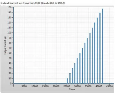
Fig. 8: Output Current in Amperes v/s Time for LT 100-P
Fig. 9: Output offset voltage when input current is 0A .Mean= 3.84mV
Fig. 10: Output voltage v/s Input current for LT 100-P
From the analysis done the following results were obtained at room temperature for LT 100-P. The graph shows that the output is linear for an input current upto 140 A. Mean value of the output waveform for zero input current is 3.84mV and variance is 13.06mV. Hence offset voltage is 3.84mV and the offset variance indicates that output is less noisy. Offset current = 3.84mV*1000/50= 76.8 mA @ 25º C. Its sensitivity as calculated in LabVIEW was found to be 48.7mV/A. Due to its good linearity at high currents it is used for current measurements in the range of 10A-100A.
5.2 Analysis of AH 3503
The AH 3503 Hall-effect current sensor is a 3-pin linear Hall Effect sensor. Its supply voltage typically ranges from 4.5V-6V. No need to use external resistor as in the case of LT 100-P. For analysis the input current was given as 10A, 20A and so on upto 100A current pulses and supply voltage was set as 5V. Its maximum nominal current value that can be appropriately measured, at 25ºC as specified in the datasheet is 100 A and offset voltage value is half of supply voltage at 25ºC. Various plots obtained for AH 3503 current sensor are shown in figures 11-15.
As seen from figure 11, when an input current in the form of pulse from 10A to 100A (with an interval of 10 A) is given, the output of AH 3503 is highly noisy. The output voltage graph for a constant 10 A input and its filtered output are shown in figure 12 and 13 respectively. Figure 14 shows the mean offset voltage obtained for AH 3503.
Fig. 11: Output voltage in Volts v/s Time for AH 3503
ISSN 2348 – 7968 Fig. 13: Filtered output voltage v/s time graph for
constant 10A input current
Fig. 14: Output mean offset voltage calculated for input current = 0A. Offset voltage Value (mean) =2.67325 V
Fig. 15: Output voltage v/s Input current for AH 3503
From the analysis done the following results were obtained at room temperature for AH 3503. The graph shows that the output is almost linear for an input current between 10 A and 100 A. The output voltage was negligible, in the range of microvolts, for measurements upto 10 A input current. Offset voltage is 2.67325V at 25ºC and 5V supply. Variance obtained is 447mV which indicates that the output is highly noisy. Its sensitivity was calculated to be 0.527mV/A, which is very less as compared to LT 100-P. Due to its highly noisy output and less sensitivity, for current measurements from few Amperes to 20A this sensor is not recommendable. Also a filter and an amplifier should be used at the output for better results.
5.3 Analysis of FHS 40-P
FHS 40-P is a very small, open loop Hall Effect transducer used for current measurements. Typical supply voltage is 5V. As per datasheet at 25º C, it can linearly measure upto 100A of input current and offset voltage is 10mV ± 10%. Here also no external sense resistor is required since it is open loop type.
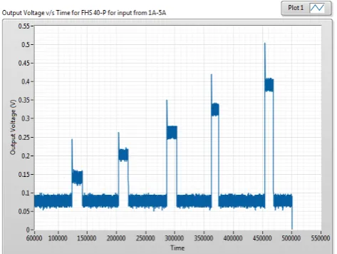
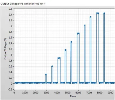
Various graphs obtained for AH 3503 current sensor are shown in figures 16-20. Figure 16 shows output voltage obtained for input current readings of 1A, 2A and so on till 5A. Similarly the next set of readings from 5A to 12A is shown in figure 17. The observations for 5A,10A,15A etc. upto 50A input is given in figure 18.
Fig 16: Output Voltage v/s Time for FHS 40-P for input from 1A-5A
ISSN 2348 – 7968
Fig 18: Output Voltage v/s Time for FHS 40-P for input from 5A-50A
Fig 19: Output Offset Voltage for zero input current; Mean=37.47mV; Variance=215.48mV
Fig 20: Output Voltage v/s Input Current graph for FHS 40-P
From the graphs obtained it is seen that the output of FHS 40-P loses its linearity for input currents above 45A although according to datasheet it is linear upto 100A. Output offset voltage obtained is 37.47mV and its variance from the mean value is 215.48mV, indicating how much the sensor is prone to output noise variations. Though its output is noisier than LT 100-P, its less noisy than AH3503. Sensitivity is 56.6812mV/A at 25º C.
5.4 Inferences
All the three sensors selected for analysis is supposed to provide good linearity for measurements upto 100A, according to their datasheets. However when tested under real conditions it was found that FHS 40-P shows good linearity only upto 45A. Similarly the output offset voltages and sensitivity values for all these sensors also shows slight variations from their datasheet values as discussed above. The actual obtained readings of sensitivity, mean offset voltage and variance from offset value for these sensors are tabulated in Table 1. The variance from offset value is simply a measurement of noise effects on the Hall Effect sensor’s output.
The output is noisier for both AH 3503 and FHS 40-P current sensors as compared to the currently used sensor LT 100-P. However when compared to the size, cost and space reduction benefits provided by FHS 40-P its noise effects are negligible and can be remedied using better filter circuits and amplifiers at its output. Hence LT 100-P can be replaced with FHS 40-P and proper signal conditioning units for accurate measurements from 1A to approximately 40A input current. AH 3503 shows negligible output voltage upto 20A input current. Also its sensitivity is very low and the output is highly noisy. Hence it is not recommendable for replacing LT 100-P with AH 3503 for current measurements from 1A-50A.
Table 1: Current Sensor Output Comparison
0B
Current Sensor
1B
Sensitivity
(mV/A)
2B
Mean Offset Voltage (mV)
3B
Offset Variance
(mV)
LT 100-P 48.7 3.84 13.06
AH 3503 0.52778 2673.25 448.26
FHS 40-P 56.6812 37.47 215.48
4. Conclusion
ISSN 2348 – 7968 done it is seen that replacement of LT 100-P
with FHS 40-P and proper conditioning circuit is a good option. In future temperature, pressure and vibration tests also should be done to decide if FHS 40-P is suitable for replacement.
Acknowledgment
The authors would like to thank all the staff members of the department of Electronics and Communication, LBSITW, Poojapura for their support, guidance and encouragement.
References
[1] Ljubomir A Kojovic, “Comparative Performance Characteristics of Current Transformers and Non-Conventional Current Sensors”, 20th International Conference on Electricity Distribution Prague, June 2009. [2] Jeffrey D. Bull, Nicolas A. F. Jaeger, and Farnoosh
Rahmatian, “A New Hybrid Current Sensor for High-Voltage Applications”, IEEE Transactions on Power Delivery, January 2005, Vol. 20, No.1.
[3] D. C. Erickson, “The use of fiber optics for communications, measurement and control within high voltage substations,” IEEE Trans. Power App. Syst., 26 February 2007, ISSN: 0018-9510, pages: 1057 – 1065.
[4] Quentin L. Willard, Austin M. Bartlett, Louis S. Harrington, and Jason C. McKay, Ernest Y. Wong, “A Systems Approach to Autonomous Space Exploration”, IEEE, E-ISBN : 978-1-4244-1286-0, April 2007, pages 1-5.
Arya Krishna S. got her degree in Electronics and Communication
engineering from Sree Chitra Thirunal College of Engineering, Trivandrum in 2012. She is currentlu pursuing her M.tech in Signal Processing from the Department of Electronics and Communication Engineering, LBSITW, Trivandrum. She has participated in few national and international conferences and has published an image processing paper in the international journal IJCSMC.
Lizy Abraham is pursuing a PhD in satellite images, and is presently