2
ndInternational Science, Social Science, Engineering and Energy Conference 2010:
Engineering Science and Management
Dark Soliton Array for Communication Security
I.S. Amiri
a,b,*, A. Afroozeh
a,c, I.N. Nawi
a, M.A. Jalil
a, A. Mohamad
a,
J. Ali
aand P.P. Yupapin
daInstitute of Advanced Photonics Science, Nanotechnology Research Alliance
Universiti Teknologi Malaysia (UTM), 81310 Johor Bahru, Malaysia
bDepartment of Physics, Islamic Azad University of Mahabad, Iran c
Department of Physics, Islamic Azad University of Jahrom, Iran
d Advanced Research Center for Photonics, Faculty of Science
King Mongkut’s Institute of Technology Ladkrabang Bangkok 10520, Thailand
Elsevier use only: Received 15 November 2010; revised 15 December 2010; accepted 20 December 2010
Abstract
A system of dark soliton array (DSA) for secured optical communication using the multiplexed dark soliton pulses is presented. Different wavelength of input soliton pulses with relevant parameters are fed into the rings system while the radii of the rings are 7 μm, 5 μm and Rd = 50 μm. Result shows that the free spectrum range of dark soliton input with the center wavelength of 1503
nm is 0.073 nm. DSA can be obtained using a series of micro ring resonators with input optical solitons of different wavelength, range from λ = 1513 nm to λ = 1517 nm. The DSA can be tuned and amplified used for many application in optical
communication such as security purposes. In transmission link, the long distance link of the multi variable network can be performed using DSA.
© 2010 Published by Elsevier Ltd.
Keywords: Center wavelength, Array generation, Multiplexer, Ring resonator
1. Introduction
In communication application, soliton can be used for long distance optical communication links. For system performance, the required minimum repeater in the link is the key advantage. However the soliton–soliton interaction, soliton collision and dispersion management must be solved [1–2]. To date, several papers have investigated dark soliton behaviors [3–4] where the detection of dark soliton is extremely difficult. Easy way for detect the dark soliton can be obtained using dark-bright conversion system. This means that the dark soliton characteristics can be used as a form of communication security which can be retrieved by the dark–bright soliton conversion [5, 6]. Dark soliton can be converted into a bright soliton after passing through a specific add/drop filter
* Corresponding author. Tel.: +6075534077; fax: +6075566162.
E-mail address: [email protected]. © 2011 Published by Elsevier Ltd.
1877–7058 © 2011 Published by Elsevier Ltd. doi:10.1016/j.proeng.2011.03.076
Procedia Engineering 8 (2011) 417–422
Open access under CC BY-NC-ND license.
[7]. The transmission signals can be transmitted in the form of dark solitons. The specific end user that is connected to the link via the specific add/drop filter can recover the signals. Dark soliton applications have been widely investigated in various applications [8–9]. In this study, the DSA which consists of an array of micro rings will be used for generation of array dark soliton in communication security.
2. Theoretical Simulation
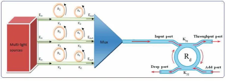
The dark soliton array can be obtained using dark soliton pulses input to a series of micro ring resonator (MRR) in single system. The stationary multiple dark soliton pulses are introduced into the MRR system, as shown in Figure 1. Each input optical field (Ein) of the dark soliton pulses input is given by [3].
0 0
tanh exp
2 in
D
T z
E A i t
T L ω
⎡ ⎤
⎡ ⎤ ⎛ ⎞
= ⎢ ⎥ ⎢⎜ ⎟− ⎥
⎝ ⎠
⎣ ⎦ ⎣ ⎦
(1)
where A and z are the optical field amplitude and propagation distance, respectively. T is the soliton pulse propagation time in the frame moving at the group velocity, T = t-β1*z, where β1and β2 are the coefficient of the linear and the second order terms of Taylor expansion of the propagation constant. 2 2
0 β
T
LD = is the dispersion
length of the soliton pulse. To in the equation is a soliton pulse propagation time at initial input (or collision pulse width), where t is the soliton phase shift time, and the frequency shift of the soliton is ω0. Equation (1) describes a pulse that keeps its temporal width invariance as it propagates and, thus, is called a temporal soliton [10]. When a soliton peak intensity (
(
2)
0 2/ΓT
β ) is given, then T0 is known. When a soliton pulse is propagated within nonlinear micro ring device, a balance should be achieved between the dispersion length (LD) and the nonlinear length (LNL=
1/ ΓφNL), where Γ = n2*k0is the length scale over which dispersive or nonlinear effects make the beam wider or narrower. For a soliton pulse, there is a balance between dispersion and nonlinear lengths, hence,
L
D=
L
NL. When light propagates within the nonlinear material (medium), the refractive index (n) of light within the medium is given byP
A
n
n
I
n
n
n
eff
)
(
2 0 20
+
=
+
=
(2)where n0 and n2 are the linear and nonlinear refractive indexes, respectively. I and P are the optical intensity and optical power, respectively. The effective mode core area of the device is given byAeff .
2 2
2 2
( ) (1 (1 ) ) (1 ) 1
( ) (1 1 (1 ) 4 1 1 sin ( ) 2
out
in
E t x
E t x x
γ κ γ φ γ κ γ κ ⎡ ⎤ ⎢ − − ⎥ = − ⎢− ⎥ ⎢ − − − + − − ⎥ ⎣ ⎦ (3)
Equation (3) indicates that a ring resonator in this particular case is very similar to a Fabry-Perot cavity, which has an input and output mirror with a field reflectivity, (1-κ ), and a fully reflecting mirror. κ is the coupling coefficient, andx=exp
(
−αL/2)
represents a roundtrip loss coefficient, φ0=kLn0 and 22 in NL=kLn E
φ are the
linear and nonlinear phase shifts, k =2π/λ is the wave propagation number in a vacuum. Where L and α are a waveguide length and linear absorption coefficient, respectively. In this work, the iterative method is used to obtain the results as shown in equation (3), similarly, when the output field is connected and input into the other ring resonators.The optical field of dark soliton pulse is input into a nonlinear series MRR. By using the appropriate parameters, we propose to use the add/drop device. This is given in detail as follows. The optical outputs of a ring resonator add/drop filter can be given by [13].
(
)
( ) (
)
(
)(
)
e e( )
k Le L k e E E n L L L n L in t cos ) 1 ( ) 1 ( 2 1 1 1 1 cos ) 1 ( ) 1 ( 2 1 2 2 1 2 1 2 2 2 1 1 2 α α α α κ κ κ κ κ κ κ κ − − − − − ⋅ − − − − + − + − ⋅ − − −
= (4)
and
(
)(
)
e e( )
k Le E E n L L L in d cos ) 1 ( ) 1 ( 2 1 1 1 2 2 1 2 1 2 2 1 2 α α α κ κ κ κ κ κ − − − − ⋅ − − − − +
= (5)
where Et and Ed represents the optical fields of the throughput and drop ports respectively. β=kneff is the propagation constant, neff is the effective refractive index of the waveguide and the circumference of the ring is
2
=
L πR, hereR is the radius of the ring. In the following, new parameters will be used for simplification: φ β= L
is the phase constant. The chaotic noise cancellation can be managed by using the specific parameters of the add/drop device, which the required signals can be retrieved by the specific users. κ1 and κ2 are coupling coefficient of add/drop filters, kn =2π /λ is the wave propagation number for in a vacuum, and where the waveguide (ring resonator) loss is
α = 0.5 dBmm-1. The fractional coupler intensity loss is γ = 0.1. In the case of add/drop device, the nonlinear refractive index is neglected.
3. Result and Discussion
Generated dark soliton pulse for pulse with 50 ns pulse width and a maximum power of 0.65 W is input into each ring resonator system with different center wavelengths is shown in Figure 1. Suitable ring parameters are used, such as ring radii and ring coupling coefficients, where R1 =7 μm and R2 =5 μm. To make the system match to the practical device [14], n0= 3.34 (In-GaAsP/InP).
The effective core areas are Aeff = 0.50 μm2 and 0.25 μm2 for MRRs. The waveguide and coupling losses are α = 0.5 dBmm−1 and γ = 0.1, respectively, and the coupling coefficients κ of the MRRs range from 0.03 to 0.1. The nonlinear refractive index is n2 = 2.2 × 10⁻¹³m2/W. In this case, the waveguide loss used is α = 0.5 dBmm−1. However, more parameters are used, as shown in Figure 1.
the parameters of the system are set as the same. For instance, the dark solitons are input into the system at the center wavelengths λ1 = 1501 nm, λ2 = 1503 nm, and λ3 = 1505 nm.
When a dark soliton propagates into the MRR system, the dark soliton collision (modulation) in the MUX system and the filtering signals within the add/drop ring (Rd) occur as shown in Figure 1. The dark soliton is generated by multilight sources at the center wavelength λ1 = 1503 nm and the filtering signals are as shown in Figure 2. The free spectral range (FSR) and the amplified power of 2.15 nm and 80W of the dark soliton are obtained when, in this case, the spectral width or called it full width at half-maximum (FWHM) of 0.073 nm is achieved. Different center wavelength are input to the micro rings system and filtered by the second ring resonator in each line of the proposed system as shown in Figure 3. The multiplexed output signals from the system is shown in Figure 3(g)
In Figure 3, the dark soliton array generated by multilight sources at center wavelengths of λ1 = 1513 nm, λ2 = 1515 nm, and λ3 = 1517 nm is presented.
͵Ǥ
We have presented the use of ring resonators to generate dark soliton arrays is which the multiplexed dark soliton pulses can be seen by using a light pulse in fiber optic loop or MRR systems. First, the multiple dark solitons are input into the series MRRs, through which multiplexed dark solitons with different center wavelengths, i.e., dark soliton arrays, can be obtained. In this study, dark soliton with FSR and amplified power respectively of 2.15 nm and 80 W can be obtained at the center wavelength of 1503 nm.
4. Acknowledgement
We would like to thank the Institute of Advanced Photonics Science, Nanotechnology Research Alliance, Universiti Teknologi Malaysia (UTM) and King Mongkut’s Institute of Technology (KMITL), Thailand for the support in research facilities. This research work has been supported by the Ministry of Higher Education (MOHE), FRGS-grant 78452.
[1] M. Ballav and A. R. Chowdhury, “On a study of diffraction and dispersion managed soliton in a cylindrical media,” Prog. Electromagn. Res. (PIER), vol. 63, pp. 33–50, 2006.
[2] R. Gangwar, S. P. Singh, and N. Singh, “Soliton based optical communication,” Prog. Electromagn. Res. (PIER), vol. 74, pp. 157–166, 2007.
[3] F. G. Gharakhili, M. Shahabadi, and M. Hakkak, “Bright and dark soliton generation in a left-handed nonlinear transmission line with series nonlinear capacitors,” Prog. Electromagn. Res. (PIER), vol. 96, pp. 237–249, 2009.
[4] A. D. Kim, W. L. Kath, and C. G. Goedde, “Stabilizing dark solitons by periodic phase-sensitive amplification,” Opt. Lett., vol. 21, pp. 465–467, 1996.
[5] K. Sarapat, N. Sangwara, K. Srinuanjan, P. P. Yupapin, and N. Pornsuwancharoen, “Novel dark-bright optical soliton conversion system and power amplification,” Opt. Eng., vol. 48, pp. 45-49, 2009.
[6] B. A. Malomed, A. Mostofi, and P. L. Chu, “Transformation of a dark soliton into a bright pulse,” J. Opt. Soc. Am. B, vol. 17, pp. 507–513, 2000.
[7] S. Mithata, N. Pornsuwancharoen, and P. P. Yupapin, “A simultaneous short wave and millimeter wave generation using a soliton pulse within a nano-waveguide,” IEEE Photonics Technol. Lett., vol. 21, pp. 932–934, 2009.
[8] S. Mitatha, “Dark soliton behaviors within the nonlinear micro and nanoring resonators and applications,” Prog. Electromagn. Res. (PIER), vol. 99, pp. 383–404, 2009.
[9] C. Finot, J. M. Dudley, and G. Millot, “Generation of dark solitons by interaction between similaritons in Raman fiber amplifiers,” Opt. Fiber Technol., vol. 12, pp. 217–226, 2006.
[10] G. P. Agarawal, Nonlinear Fiber Optics, 4th ed. (Academic, 2007).
[11] P. P. Yupapin, N. Pornsuwanchroen, and S. Chaiyasoonthorn, “Attosecond pulse generation using nonlinear microring resonators,” Microwave Opt. Technol. Lett., vol. 50, pp. 3108–3110, 2008.
[12] P. P. Yupapin and W. Suwancharoen, “Chaotic signal generation and cancellation using a micro ring resonator incorporating an optical add/drop multiplexer,” Opt. Commun., vol. 280, pp. 343–350, 2007.
[13] P. P. Yupapin, P. Saeung, and C. Li, “Characteristics of complementary ring-resonator add/drop filters modeling by using graphical approach,” Opt. Commun., vol. 272, pp. 81–86, 2007.