20th International Conference on Structural Mechanics in Reactor Technology (SMiRT 20) Espoo, Finland, August 9-14, 2009 SMiRT 20-Division III, Paper 1962
AREVA’s fatigue concept (AFC) – an integrated and multidisciplinary approach
to the fatigue assessment of NPP components
Jürgen Rudolph
a, Steffen Bergholz
aand Nikolaus Wirtz
aa
Department NEEA-G, AREVA NP GmbH, Erlangen, Germany, e-mail: [email protected]
Keywords: AREVA Fatigue Concept (AFC), Fatigue Monitoring System (FAMOS), thermal transient loading, simplified fatigue estimation, transient catalogue, detailed fatigue and ratcheting check.
1
ABSTRACT
The prevention of fatigue damages is to be considered as a crucial issue in the view of changing boundary conditions: code modifications, lifetime extension, new plants with operating periods of 60 years. The AREVA fatigue concept provides for a multiple step and multidisciplinary process (process engineering, fatigue monitoring, fatigue analyses etc.) against fatigue before and during the entire operation of NPP’s. Fatigue analyses are based on the real operational loads measured continuously on site in the plant by means of an installed fatigue monitoring system. Hence, qualified fatigue usage factors can be determined. Locations of potential fatigue failure are reliably identified and expensive costs for inspection can be essentially reduced. The direct processing of the measured temperatures is immediately used for a first automated fast fatigue estimation. In the framework of the Periodic Safety Inspection (PSI) a detailed fatigue check conforming to the code rules and based on the real loads is recommended. One peculiarity is the additional check against progressive plastic deformation (ratcheting). In the case of the elastic plastic approach much care has to be taken with respect to the application of an appropriate material law and extrapolation procedures emanating from a low number of analyzed cycles.
2
INTRODUCTION
Figure 1 shows the typical arrangement of components within the primary circuit of a pressure water reactor (PWR). The possible layout of measuring points for in-service fatigue monitoring is marked with full circles. Thus, the main role of the temperature measurement system can easily be identified.
Figure 1: Primary circuit of a pressurized water reactor (PWR)
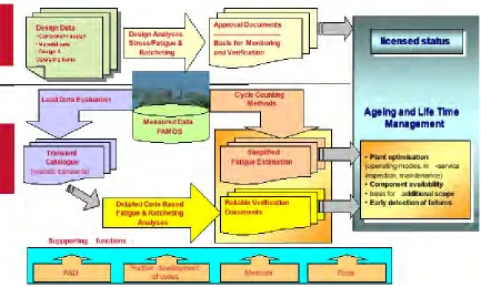
The principal modules of the AREVA concept of design against fatigue are schematically shown and logically combined in Figure 2.
Figure 2: Principal modules of the AREVA integrated concept of fatigue design
However, the first analysis is carried out even before the initial start-up. In this design stage, calculated usage factors above 1.0 require more refined analyses. The real transient loads are recorded and processed on site based on FAMOS (Fatigue Monitoring System). A simplified fatigue estimation method (one branch in Figure 2) is directly combined with the measuring system. This simplified fatigue estimation is carried out after every operational cycle. This procedure is highly automated and allows for an estimation of the recent usage factor. In this process, implausible measured data have to be eliminated A further division into classes is carried out and usage factors are estimated by application of the rainflow algorithm.
As temperatures are measured on the outer wall and fatigue relevant locations are usually located on the inner wall the inverse temperature field problem has to be solved appropriately as one modular task for the specification of realistic transients and subsequent thermomechanical analyses. Furthermore, temperatures are measured at thin walled tubes within the piping system. So, temperature and stress profiles due to the measurements have to be transformed into profiles at the fatigue relevant locations (e.g. thick cross sections, nozzles, flanges and pipe bends).
In the framework of the Periodic Safety Inspection (PSI) a detailed fatigue check conforming to the code rules is carried out in order to determine the current state of the plant (see workflow in Figure 2). This fatigue check is based on monitored loads and updated specification of thermal transient loads and finite element analyses in connection with the local strain approach (strain life approach) to design against fatigue. There is still potential with respect to a less conservative specification of the thermal loads. Practicability still demands for the definition of some covering unit transients and the allocation of the real number of occurrences (pressure, temperature and mass flows). These unit transients are used as load data in the Finite Element (FE) stress and strain analyses and evaluated in terms of the applied design code [ASME (2007), KTA (1996), RCC-M (2000)] the intermediate step of load determination by Computational Fluid Dynamics (CFD) might be part of the workflow and will gain in importance in the future. The determination of realistic heat transfer coefficients as a function of time is an important task. The FE analyses always embrace transient thermal determination of the temperature field and subsequent determination of (local) stresses and strains. The latter analyses might be simplified elastic plastic or fully elastic plastic. One Code requirement is the additional check against progressive plastic deformation (ratcheting).
3
FIRST DESIGN ANALYSIS BEFORE OPERATION
Before commissioning and operation of the plant a catalogue of presumed thermal transients is compiled. Consequently, these specified thermal loads have to be considered as design transients in contrast to the real transients based on temperature measurement during operation. In the past, the anticipated transients covered 40 years. Now, the period to be considered is even 60 years. The specification is done for level A and level B, e.g. normal and upset conditions as well as partially levels C and P (emergency and testing). The code based fatigue analysis considers level A and level B loads in the design phase. Design transients before operation are specified according to different plant models and experiences. As a general rule, the specified transients are conservative with respect to frequency of occurrence, temperature range, rate of temperature change and load type (thermal shock, thermal stratification). The usage factors calculated in the design fatigue analysis will considerably differ from the results of the more detailed consideration of the real operational (thermal) loads. As a consequence, usage factors around 1.0 are still tolerable in the design phase. They indicate the positions of further analysis which is another aspect of the advantageous application of the first design analysis before operation. This reliable identification of points of interest is valuable under different aspects. These locations are selected for future instrumentation and nondestructive testing. Thus, the pre-operational analysis is a valuable aid for the specification of the testing concept. It allows for an estimation of the amount of testing required. Furthermore, it is still possible to exert influence on the design and construction of the components and the operation mode of the plant. The consequences of non-optimal operation modes can clearly be shown. Plant staff is sensitized from the very beginning to the influence of operation on the lifetime of components. It contributes to the development of a deepened consciousness of responsibility and safety.
Thermal transients with low influence on the fatigue behavior are identified as well. The design codes offer procedures for the exemption from fatigue analysis for non significant loads. The so called six points check should be mentioned. This procedure is specified for primary circuit components in ASME-Code [ASME (2007)], Section III, Division 1, paragraph NB-3222.4 and nearly identically in the German KTA 3201.2 [KTA (1996)], paragraph 7.8.2. Note that all six points have to be simultaneously fulfilled. The points concerning pressure and temperature transients are of special interest in this context. Non significant pressure ranges ΔpNS are calculated as a function of the design pressure pD, the admissible stress amplitude at
the endurance limit Sa(N=10 6
) and the Sm-value of the material at operational temperature while non
significant temperature ranges ΔTNS are calculated as a function of the admissible stress amplitude at the
endurance limit Sa(N=106), Young’s modulus E and the linear thermal expansion coefficient α:
(
)
mT a D NS S N S p p 6 10 3 1 = ! ! <" ;
(
)
!
"
"
=
<
#
E
N
S
T
a NS2
10
6 (1)As far as non primary circuit (class 2) components are concerned the German KTA rules give further exemption criteria in KTA 3211.2, paragraph 7.8.1.2.1 [KTA (1992)].
It should be mentioned that Section B3000 (Design) of the recent issues of the French RCC-M Code [RCC-M (2000)] do not contain a comparable procedure for a simplified fatigue check. Hence, it depends on the code to be applied if this kind of fatigue analysis is admissible for nuclear power plant components.
4
THE AREVA ADVANCED FATIGUE MONITORING SYSTEM (FAMOS)
well as many plants in other countries were equipped with FAMOS (more than 20 NPP’s since 1988; 20–50 measurement sections and up to 150 thermocouples per plant).
The objectives of FAMOS [Kleinöder (2007)] can be summarized as follows:
• Determining the fatigue status of the most highly stressed components,
• Identifying operating modes which are unfavorable to fatigue,
• Establishing a basis for fatigue analysis based on realistic operating loads and
• Using the results for lifetime management and life-time extension.
• In fact, the practical application resulted in various improvements of operating procedures, transient catalogues and fatigue results. FAMOS proved to be a reliable basis for the integrity concept, inspection plans and lifetime extension considerations.
In the following the technical bases of FAMOS are shortly described. Figure 3 shows the application of thermocouples at the outer surface of a piping section. The standard configuration consists of a mounting strap with the thermocouples and a second clamping strap used to press the thermocouples to the surface of the pipe. In 1996, a new measurement section which significantly improved the thermal sensitivity was successfully introduced. The FAMOS special instrumentation features consist of seven temperature trans-ducers around one half of the pipe circumference in order to detect thermal stratification. This arrangement of thermocouples resolves the course of temperature as a function of time and the vertical coordinate y. In case of anticipated plug flow the application of only two thermocouples (T1 and T7 according to Figure 3) is
sufficient.
Thermocouple s
Mounting Strap Cover
shell
Figure 3: FAMOS measurement section
The practical installation of FAMOS in a nuclear power plant starts with the generation of a so called FAMOS manual. This process contains a weak point analysis identifying components in the primary circuit and its safety systems as well as the secondary circuit that are expected to be particularly prone to fatigue damage. All design documents and operating experience are considered. A measuring point plan is elaborated and all activities are coordinated with the plant operator and if required with independent experts. As an example, points of interest within the primary circuit of a nuclear power plant are marked with full circles in Figure 1. In this case the following components are fatigue monitoring locations: the surgeline, the pressurizer spray lines, the nozzle of the residual heat removal system at the cold loop, the volume control system, the nozzle at the primary loop, the recuperative heat exchanger and the feed water nozzle at the steam generator.
5
DETAILED DATA PROCESSING / SPECIFICATION OF THERMAL TRANSIENTS
An important connecting link between the recording of measurements and the stress and fatigue analysis is the specification of thermal loads. For this task it is essential to use the specific knowledge of system and process engineers to identify the relevant load mechanism. Consequently, it is possible to develop smarter operational modes or more favorable hardware designs to achieve lower fatigue values which are necessary for an extended lifetime (see Figure 4). Additionally, this procedure is a plausibility check of the available data. As a result, implausible data are detected and adjusted. The staff is sensitized to the consequences of certain operational actions, preferably beginning with the commissioning and initial start-up phase. Note that the transients can be significantly different in one power plant compared to another one due to the numerous influences. In spite of the strict regulations of the operational manuals the operator still takes an active influence on the operation of the power plant. If there is no existing compilation of the load cases which must be considered, e.g. from the permission of the plant, such a compilation must be created. This can be done specific for the system or for the whole pressure retaining boundary. In some cases such an overall load case compilation was carried out for German power plants for the pressure retaining boundary together with the secondary side systems and the most important neighboring systems such as the Chemical and Volume Control System (CVCS) and the Residual Heat Removal System (RHRS).
All the information is used for the specification of the plant specific thermodynamic loads in official reports and transient handbooks. For thermal loads three types of specification are state of the art:
• Design specification for new plants or backfitting projects. This type of specification is based on theoretical analysis as well as measurements in comparable plants. It is necessary to reflect all possible load cases in the lifetime of the plant.
• Determination of the actual fatigue value (note that it is only possible to examine an upper limit of this number). Here all the events in the present lifetime must be considered which are relevant for loading. Normally this exercise will be repeated every 10 years.
• Overall specification for all possible and hypothetical load cases which must be considered for the lifetime.
Lifetime- Monitoring
Design & Construction
Operating Modes Thermodynamic Loading Data
Stress & Fatique - Analysis
Figure 4: Interaction between operating mode, loading data and stress & fatigue analysis
The first step to specify thermal loads is the identification of the operational processes leading to relevant transients of temperature and/or pressure. For these events an appropriate number of model transients is selected. Usually, it is necessary to split up these model transients into subclasses which are different e.g. in the temperature difference of the transient.
In a next step all the (relevant) events in the considered lifetime period are allocated to the specified model transients (or the corresponding subclasses). All the factors defining the model transient or the corresponding subclasses must be specified conservatively. All allocated events must be covered. Occasionally, an iterative process is required in order to achieve suitable model transients with an acceptable measure of conservatism.
conditions (e.g. thermal stratification can be expected between pressurizer temperature and main coolant temperature). Knowledge of the processes and the operation of the systems is essential. As an example, a spray event under emergency conditions can be derived from a spray event of the start-up of the plant. Normally, only part of the required information is available. Obviously, the exchange of experiences and information between similar plants is synergetic and is a valuable aid in the permanent improvement of the entire process of data evaluation (see Figure 2). This holds particularly true for the German CONVOY plants which have a very similar basic design. If the conditions are not identical it is still possible to acquire additional information by transfer and rescaling to hypothetical boundary conditions. Again, missing information has to be complemented based on an excellent knowledge of systems and processes of the plant.
Finally, the specified thermodynamic loading data are the basis for the code based fatigue and ratcheting analyses. It should be pointed out that the quality and accuracy of the thermomechanical analyses highly depends on the plausibility of the specified transient loads. Together with the information about e.g. fluid dynamical or seismic loads the following steps in the chain of certification can be done. It is pointed out that the FAMOS system should be installed in the power plant from the very beginning of operation, i.e. in the commissioning and initial start-up phase. This phase is often characterized by the highest loads of the entire lifetime of the power plant.
6
SIMPLIFIED STRESS BASED FATIGUE (SSBF) ESTIMATION
The results of the temperature measurement are to be processed quickly in order to get a first estimation of the fatigue state. One important task before the simplified and automated evaluation is the verification of the acquired data. Detection and adjustment of implausible data are parts of this process. These plausibility and quality checks of the measured data have to be done by experienced specialists. The result is a preprocessed database for (automated) data evaluation and fatigue assessment.
In the very first step of the simplified fatigue assessment procedure the changes of temperatures are subject to a rainflow cycle counting algorithm [Matsuishi (1968)]. In this process the temperature ranges at the locations of measurement are identified, counted and classified. These thermal load cycles are input data for a stress and fatigue assessment of the monitored components based on conservative analytical computation formulae. This rough real time fatigue estimation is done after every operational cycle and allows for a direct comparison of thermal loads and fatigue damage increments as well as an evaluation of the actual fatigue usage. The result of this simplified fatigue assessment is usually conservative (idealized thermal shock assumption, thermal stratification with sharp separation). Although the correlation of the real temperature ranges is fairly simple it is suitable for a comparison of different real sequences of loads and allows for a qualitative evaluation of the mode of operation and the detection of fatigue critical locations. Furthermore, the investigation of the results allows for the detection of anomalies.
It is important to distinguish this cycle based method for Simplified Stress Based Fatigue (SSBF) from the frequently applied Event Based Fatigue Method for the approximate assessment of fatigue damage increments based on the recording and evaluation of so called counting lists of load cases. In the design phase the calculated fatigue effects are related to certain presumed events. Such an event, to which a defined set of fatigue load cycles is assigned, may be for instance the unit start-up, the unit shut down, power increase or decrease, exchange of water, emergency shut down etc.. The fatigue calculation assigns a fraction of fatigue damage to each of these events. The fatigue fraction is then multiplied by the presumed number of occurrences of the event during the component’s planned service life. The cumulated fatigue is obtained by linear summation of all fatigue fractions of all the events considered (Miner’s rule). Event based fatigue methods compare the numbers of occurrences of operational events with the presumed events from the design phase. The evaluation does not consider occurred loads. Thus, it is not investigated whether the course of events during operation complies with those from the design phase. As an example, different start-up events may cause different fatigue usage contributions due to different numbers of hot standby hours and the derived different thermal loads.
7
DETAILED CODE BASED FATIGUE AND RATCHETING ANALYSIS
7.1 Code based fatigue analysis
The detailed code based fatigue analysis is usually carried out after a certain time period of plant operation (e.g. 10 years) in the framework of the periodic safety inspection. Loading data of the operational period as well as anticipated loads of future operation are used as essential input parameters. Hence, usage factors are calculated for the current state of the plant and until the end of life (e.g. 40 or 60 years).
The simplified elastic-plastic fatigue analysis based on elastic FEA and plasticity correction (fatigue penalty or strain concentration factors Ke) e.g. according to paragraph 7.8.4 of [KTA (1996)] or equally NB 3228.5 of [ASME (2007)] is known to yield often overly conservative results [Adams (2005), Hoffmann (1985)]. In the practical application this will yield high calculated usage factors. As a consequence, the less conservative elastic-plastic fatigue analysis methodology based on non-linear FEA will often be used for fatigue design. This is associated with an increased calculation effort. Computing times for complex 3D geometries and numerous transients may be significant. Under these circumstances the specified transients have to be rearranged in a small set (often 7 to 10) of covering transients for calculation purposes.
The possible modification of design codes with respect to more severe fatigue curves [O’Donnell (2007)] and the consideration of environmental, surface, load sequence and other effects [NUREG/CR-6909 (2007)] will significantly influence the code based fatigue design. Of course, these developments are attentively fol-lowed and actively accompanied (see “supporting functions” in Figure 2). For the practical fatigue calculation process, conservative assumptions will have to be scrutinized in order to compensate the more severe fatigue assessment approach.
7.2 FE modeling requirements
Finite element analyses as one essential pillar of the code based fatigue approach have to meet strict quality requirements. Results obtained by different commercial FE codes and by different CAE engineers must be comparable. The appropriate idealization and discretization strategy has to be formulated in terms of mandatory rules. Where applicable such rules should be verified by checking calculations and convergence tests. The elaboration and formulation of modeling guidelines is part of AREVA’s quality management process. Note that special rules apply for thermal transient analyses in terms of discretization requirements and time step sizes. The compliance with such rules ensures an accurate determination of notch stresses, thermal stresses and stress gradients.
7.3 Ratcheting: incremental elastic-plastic analysis
Ratcheting as a possible damage mechanism is a design code relevant issue. The ratcheting phenomenon is defined in paragraph NB-3213.33 of ASME (2007)] as follows: Ratcheting is a progressive incremental inelastic deformation or strain which can occur in a component that is subjected to variations of mechanical stress, thermal stress, or both. In fact, ratcheting is a complex phenomenon of cyclic plasticity. The realistic simulation of the process of strain accumulation requires the application of the incremental theory of plasticity. In this case, care has to be taken with respect to the application of an appropriate material law [Bari (2000)]. The key for any successful ratcheting simulation is the description of the kinematic hardening i.e. the translation of the yield surface in stress space. Classical kinematic material models (Prager, Besseling etc.) often do not describe this translation [Rahman (2005)] in a sufficiently accurate way. As a consequence, they fail in the simulation of experimentally proved load paths. Both considerable over- and underestimations are possible. It is important to point out that available experimental data and research results mostly refer to mechanical loading. By contrast, components of nuclear power plants are mainly subject to thermal transient loading conditions. This requires special emphasis on thermal ratcheting issues. It does not only demand for the determination of the material parameters as a function of temperature but for the additional implementation of a differential temperature term. AREVA is actually implementing this expanded version of the Ohno & Wang material law as a user routine within the commercial finite element code ANSYS® [ANSYS (2007), Willuweit (2009)].
As an extended post processing procedure the calculation of the plastic main tensile strain increment per cycle and appropriate extrapolation schemes emanating from few analyzed cycles are indispensable for the determination and evaluation of accumulated plastic strains within the ratcheting check.
REQUIREMENTS
8.1 Description of fatigue damage based on short crack fracture mechanics
Instead of using the abstract notion of a usage factor fatigue damage can be interpreted as the initiation and propagation of microscopically, physically and mechanically short cracks to an engineering crack size of about 0.5-3.0 mm. Fatigue curves of un-notched (polished) standard specimens resulting from strain controlled tests usually describe this limiting damage criterion. This is one characteristic feature of the local strain approach. The design fatigue curves of the applicable design codes [ASME (2007), KTA (1996), RCC-M (2000)] are based on these types of tests. The phase of technical crack initiation to an engineering crack size as part of the real fatigue damage process can alternatively be described by means of short crack fracture mechanics [Vormwald (1991), Vormwald (1994)]. This approach allows for a realistic description of the fatigue damage process, the determination of more accurate/realistic usage factors, the additional consideration of the influence of surface roughness by a fracture mechanical interpretation as an initial damage (crack), the consideration of size and gradient effects, the implicit consideration of mean stress effects by simulation of the crack closure behavior, the realistic interpretation of load sequence effects by consideration of the transient crack closure behavior under variable amplitude loading and the evaluation of NDT findings on the basis of experimentally approved crack propagation laws. Furthermore, this approach has the future potential of considering environmental effects on a fracture mechanics basis.
The concept has already been extended to multiaxial loading conditions [Savaides (1997)] and is successfully applied for the simulation of fatigue damage of engineering components with emphasis on mechanical loadings [Savaides (2001)]. The strengthening of the approach for thermo-mechanical loading conditions is part of AREVA’s current research activities in a cooperation between AREVA, the TU Darmstadt and the VGB PowerTech technical association of companies of power plant operators and manufacturers [Bauerbach (2009)]. The calculated local elastic-plastic stresses and strains and the derived fracture mechanical parameters serve as input data for the fracture mechanics based laws of crack initiation and crack propagation. The short crack model should be combined with replica measurement of the crack growth. Hence, measured and modeled crack lengths can be compared in a very early stage of fatigue damage. As a result, NDT findings of short fatigue cracks can be directly allocated to the real usage of the material.
8.2 Direct scanning of fatigue damage
A long-term R&D project has been launched by AREVA with the aim of being able to detect fatigue damage directly on the component based on NDT methods. Basic research results of various German institutes give evidence that the different stages of fatigue damage in power plant steels can be successfully related to NDT data [Palm (2005)]. A new practical approach to the evaluation of fatigue damage based on the fractal dimension of deformation structures is promising [Schreiber (2005)] in this context. It was found that the fractal dimension of the deformation structure derived from the surface topography increases during fatigue load. Simultaneously, the fractal dimension of the changing magnetic domain structure shows the same behavior. Thus, magnetic noise measurements collect information on small sample regions. The scaling parameter “fractal dimension” is derived and correlated to fatigue life [Schreiber (2005)]. AREVA aims at the application and verification of this method.
9
CONCLUSIONS
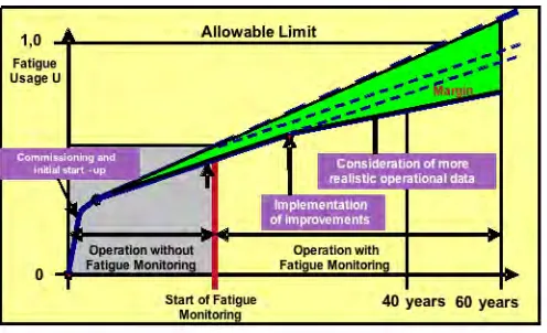
Figure 5: Development of fatigue usage factor considering local monitoring and improvements
The application of fatigue monitoring in an early phase of plant operation permits an early implementation of improvements and consideration of more realistic operational data in the detailed fatigue analysis. As a rule of thumb the actual operating conditions result in lower fatigue usage than those applied in the design calculations. Of course, additional loadings may occur as a result of the mode of operation or faulting conditions within specific systems.
The main modules are the first design analysis before operation, the advanced load monitoring system, the simplified fatigue assessment, the detailed data processing combined with the specification of occurring thermodynamic loads and the code based fatigue and ratcheting analysis. The fatigue monitoring process should be considered from the very beginning (initial start-up) until the end of life (e.g. 60 years). As all modules are closely connected, it is reasonable to apply the approach as a whole with an additional cost reduction effect compared to separate solutions. Thus, the integrated fatigue approach makes a significant contribution to the operational availability and the protection of investment.
Acknowledgements. Of course, the implementation of the AREVA integrated fatigue concept depends on the coordination of numerous specialists of various disciplines in a cooperative effort. This paper gives a descriptive overview of the ongoing process. The authors wish to express special thanks to the following colleagues for their valuable contributions, helpful discussions and amendments to the manuscript: K. Degmayr, G. Desfontaines, M. Franz, F. Guena, P. Gilles, N. Gillet, R. Gurdal, S. Krüger, W. Kleinöder, H. Lang, C. Pöckl, P. Quinot, G. Richter, G. Schön, K. Schramm, P. Ulmer, A. Willuweit, K. Wirtz.
REFERENCES
Adams, S.A. 2005. An Alternate Simplified Elastic-Plastic Analysis Method. ASME Code correspondence. Technical Support Document, January 19, 2005
ANSYS Rev. 11. 2007. Multi Purpose Finite Elemente Code
ASME Boiler & Pressure Vessel Code. 2007.
Section III, Division 1 – Subsection NB: Class 1 Components. Rules for Construction of Nuclear Power Plant Components.
Bari, S.; Hassan, T. 2000. Anatomy of coupled constitutive models for ratcheting simulation. International Journal of Plasticity. Vol. 16. P. 381-409
Bauerbach, K., Vormwald, M., Rudolph, J. 2009. Fatigue assessment of nuclear power plant components subjected to thermal cyclic loading. PVP-2009-77450.
Proceedings of PVP-2009, 2009 ASME Pressure Vessels and Piping Division Conference July 26-30, 2009, Prague, Czech Republic
Hoffmann, M., Seeger, T., Führing, H. 1985. Proposal for an improvement of the Ke-procedure of the
ASME-Code.
Technical University of Darmstadt, FF-2/1985
Proceedings of the International Conference “Nuclear Energy for New Europe 2007”, Portoroz, Slovenia, September 10-13, 2007
KTA 3201.2 (06/96). 1996. Components of the Reactor Coolant Pressure Boundary of Light Water Reactors Part 2: Design and Analysis
KTA 3211.2 (06/92). 1992. Pressure and Activity Retaining Components of Systems Outside the Primary Circuit
Part 2: Design and Analysis
Matsuishi, M., Endo, T. 1968. Fatigue of metals subjected to varying stresses.
Proceedings of the Kyushu branch of the Japanese Society of Mechanical Engineers, March 1968
NUREG/CR-6909 ANL-06/08. 2007. Effect of LWR Coolant Environments on the Fatigue Life of Reactor Materials. Final Report.
Argonne National Laboratory, February 2007
O’Donnell, B. 2007. Proposed Section III Fatigue Design Curves for Air Environments. ASME Code correspondence, November 7, 2007
Palm, S., Gertkemper, H., Knoch, P., Maile, K. 2005. A study of the early stages of fatigue damage in power plant steels.
Proceedings of the 31st MPA-Seminar in conjunction with the symposium “Materials & Components Behaviour in Energy & Plant Technology”, Stuttgart, Germany, October 13-14, 2005
Rahman, S.M., Hassan, T. 2005. Advanced Cyclic Plasticity Models in Simulating Ratcheting Responses of Straight and Elbow Piping Components, and Notched Plates.
Proceedings of PVP-2005, Denver, Colorado, USA
RCC-M Edition 2000, Section I, Subsection B: Class 1 components.
Design and Construction Rules for Mechanical Components of PWR Nuclear Islands
Savaidis, G., Seeger, T. 1997. Consideration of Multiaxiality in Fatigue Life Prediction Using the Closure Concept.
Fatigue Fract. Engng. Mater. Struct. Vol. 20, No. 7, P. 985-1004
Savaidis, G., Savaidis, A., Seeger, T. 2001. Engineering Components under Multiaxial Loading. Fatigue Analysis and Lifetime Evaluation.
MP Materialprüfung. Vol. 43, No. 3, P. 76-86
Schreiber, J., Kröning, M. 2005. Evaluation of fatigue damage of steel for nuclear power stations by the fractal features of deformation structures and their noise behaviour (in German language).
Proceedings of the 31st MPA-Seminar in conjunction with the symposium “Materials & Components Behaviour in Energy & Plant Technology”, Stuttgart, Germany, October 13-14, 2005
Vormwald, M. 1991. The Consequences of Short Crack Closure on Fatigue Crack Growth Under Variable Amplitude Loading.
Fatigue Fract. Engng. Mater. Struct. Vol. 14, No. 2/3, P. 205-225
Vormwald, M., Heuler, P., Krae, C. 1994. Spectrum Fatigue Life Assessment of Notched Specimens Using a Fracture Mechanics Based Approach.
ASTM STP 1231, P. 221-240