DEFINITY
®
Enterprise Communications Server
Release 8.2
Administration for Network Connectivity
555-233-504
Comcode 108678749
Issue 1
Copyright 2000, Lucent Technologies All Rights Reserved
Printed in U.S.A.
Notice
Every effort was made to ensure that the information in this book was complete and accurate at the time of printing. However, information is subject to change.
Your Responsibility for Your System’s Security
Toll fraud is the unauthorized use of your telecommunications system by an unauthorized party, for example, persons other than your com-pany’s employees, agents, subcontractors, or persons working on your company’s behalf. Note that there may be a risk of toll fraud associ-ated with your telecommunications system and, if toll fraud occurs, it can result in substantial additional charges for your telecommunica-tions services.
You and your system manager are responsible for the security of your system, such as programming and configuring your equipment to pre-vent unauthorized use. The system manager is also responsible for reading all installation, instruction, and system administration docu-ments provided with this product in order to fully understand the fea-tures that can introduce risk of toll fraud and the steps that can be taken to reduce that risk. Lucent Technologies does not warrant that this product is immune from or will prevent unauthorized use of com-mon-carrier telecommunication services or facilities accessed through or connected to it. Lucent Technologies will not be responsible for any charges that result from such unauthorized use.
Lucent Technologies Fraud Intervention
If you suspect that you are being victimized by toll fraud and you need technical support or assistance, call Technical Service Center Toll Fraud Intervention Hotline at 1 800 643-2353 or contact you Lucent representative.
Federal Communications Commission Statement
Part 15: Class A Statement. This equipment has been tested and found to comply with the limits for a Class A digital device, pursuant to Part 15 of the FCC Rules. These limits are designed to provide rea-sonable protection against harmful interference when the equipment is operated in a commercial environment. This equipment generates, uses, and can radiate radio-frequency energy and, if not installed and used in accordance with the instructions, may cause harmful interfer-ence to radio communications. Operation of this equipment in a resi-dential area is likely to cause harmful interference, in which case the user will be required to correct the interference at his own expense.
Part 68: Network Registration Number. This equipment is regis-tered with the FCC in accordance with Part 68 of the FCC Rules. It is identified by FCC registration number AS593M-13283-MF-E.
Part 68: Answer-Supervision Signaling. Allowing this equipment to be operated in a manner that does not provide proper answer-supervi-sion signaling is in violation of Part 68 Rules. This equipment returns answer-supervision signals to the public switched network when:
• Answered by the called station • Answered by the attendant
• Routed to a recorded announcement that can be administered by the CPE user
This equipment returns answer-supervision signals on all DID calls forwarded back to the public switched telephone network. Permissible exceptions are:
Canadian Department of Communications (DOC) Interference Information
This digital apparatus does not exceed the Class A limits for radio noise emissions set out in the radio interference regulations of the Canadian Department of Communications.
Le Présent Appareil Nomérique n’émet pas de bruits radioélectriques dépassant les limites applicables aux appareils numériques de la class A préscrites dans le reglement sur le brouillage radioélectrique édicté par le ministére des Communications du Canada.
Trademarks
See the preface of this document.
Ordering Information
Call: Lucent Technologies BCS Publications Center US Voice 1 888 582 3688
US Fax 1 800 566 9568 Canada Voice +317 322 6619
Europe, Middle East, Africa Voice +317 322 6416 Asia, China, Pacific Region,
Caribbean, Latin America Voice +317 322 6411 Non-US Fax 1 317 322 6699
Write: Lucent Technologies BCS Publications Center 2855 N. Franklin Road, Indianapolis, IN 46219 Order: Document No. 555-233-504
Comcode 108678749 Issue 1, April 2000
For additional documents, refer to the appedix, “References.”
You can be placed on a standing order list for this and other docu-ments you may need. Standing order will enable you to automatically receive updated versions of individual documents or document sets, billed to account information that you provide. For more information on standing orders, or to be put on a list to receive future issues of this document, contact the Lucent Technologies Publications Center.
European Union Declaration of Conformity
The “CE” mark affixed to the DEFINITY® equipment described in this book indicates that the equipment conforms to the following European Union (EU) Directives:
• Electromagnetic Compatibility (89/336/EEC) • Low Voltage (73/23/EEC)
• Telecommunications Terminal Equipment (TTE) i-CTR3 BRI and i-CTR4 PRI
For more information on standards compliance, contact your local dis-tributor.
Comments
To comment on this document, return the comment card at the front of the document.
Acknowledgment
Contents
Preface
ix
Purpose. . . ix
Audience . . . ix
Issue Status . . . ix
Organization . . . xiv
Terminology. . . .xv
How to access this book from the web . . . xvi
How to order more copies . . . xvi
Tell us what you think . . . xvii
How to Order Books . . . xvii
How to Comment on This Book . . . xvii
Where to Call for Technical Support . . . xviii
Trademarks . . . xix
1 Networking Overview
1
DEFINITY Switch Connectivity . . . 1Connectivity Overview. . . 1
Release 8 Hardware Requirements . . . 7
Hardware Requirements for Upgrades from Pre-R7 Switches . . . 7
DEFINITY Connection types and capacities . . . 9
IP Softphones . . . 11
IP Addressing . . . 13
Physical Addressing. . . 13
Logical Addressing . . . 13
Subnetting . . . 16
Default Gateway . . . 22
When to use IP routes. . . 23
2 H.323 Trunks
31
Overview . . . 31IP Solutions . . . 31
IP-Connected Trunks . . . 32
IP Softphones . . . 32
H.323 Trunk Administration. . . 33
Enabling Administration . . . 33
H.323 Trunk Administration — Task Summary . . . 36
H.323 Trunk Administration — Task Detail . . . 38
Troubleshooting IP Solutions . . . 50
H.323 Trunk Problem Solving . . . 50
Contents
3 C-LAN Administration
53
Overview . . . .53
Configurations . . . .56
Intuity AUDIX LAN Setup Summary . . . . 59
CMS LAN Setup Summary . . . .59
Configuration 1: R8r <—ppp—> R8si . . . .60
Configuration 2: R7r (+CMS) <—ethernet—> R7csi . . . 73
Intuity System Administration . . . . 92
Administer Subscribers . . . . 95
Worksheet A: Names and IP Addresses for Lucent Intuity System. . . . 96
Worksheet B: LAN Data for the Lucent Intuity System . . . . 97
Configuration 3: R8si<—x.25 —> R8r Gateway <—ethernet—> R8si . . . 99
Configuration 4: R8csi <—ISDN—> R8si Gateway <—ppp—> R8csi . . . 124
Configuration 5A: R8csi <—ppp—> R8r (one C-LAN) <—ethernet—> R8si . . . 146
Configuration 5B: R8csi <—ppp—> R8r (2 C-LANs) <—ethernet—> R8si. . . 171
4 Networking Example
203
Overview . . . .203Network Diagram . . . . 204
Task Summary . . . 205
Link/Channel/TSC Map . . . 206
Network Map . . . 207
Switch-Node 1 Administration . . . 208
DS1 Circuit Packs . . . . 208
Dial Plan . . . 209
Signaling Group . . . 210
Synchronization Plan . . . . 210
Trunk Groups . . . 211
Uniform Dialing Plan . . . . 216
AAR Digit Analysis . . . . 216
ISDN TSC Gateway Channel Assignment . . . 217
Routing Patterns . . . 217
Node Names . . . . 218
Data Modules . . . 219
Processor Channel Assignments . . . 221
Switch-Node 2 Administration . . . 222
DS1 Circuit Packs . . . . 222
Dial Plan . . . 222
Synchronization Plan . . . . 223
Trunk Goups . . . 223
Uniform Dialing Paln . . . . 224
AAR Digit Analysis . . . . 225
Routing Patterns . . . 225
Data Modules . . . 225
Contents
Switch-Node 3 Administration. . . 228
DS1 Circuit Packs . . . . 228
Dial Plan . . . . 228
Synchronization Plan . . . . 229
Signaling Group . . . . 229
Trunk Groups . . . . 230
Uniform Dialing Paln . . . . 231
AAR Digit Analysis . . . . 231
Routing Patterns . . . . 232
Hunt Group . . . . 232
Switch-Node 4 Administration. . . 233
Bus Bridge . . . . 233
DS1 Circuit Packs . . . . 233
Dial Plan . . . . 234
Synchronization Plan . . . . 234
. . . . 234
Trunk Groups . . . . 235
Uniform Dialing Paln . . . . 237
AAR Digit Analysis . . . . 237
Routing Patterns . . . . 237
Node Names . . . . 238
Data Modules . . . . 238
Processor Channel Assignments . . . . 239
IP Routing . . . . 239
IP Routing . . . . 239
Hunt Group . . . . 240
Intuity Translations for DCS AUDIX . . . 241
CMS Administration . . . 241
Appendix A: Screens Reference
243
Networking Screens. . . . 243Other Network-Related DEFINITY Screens . . . . 244
Networking Screens . . . 245
Node Names . . . . 245
page 1 . . . . 245
Pages 2 – 6 . . . . 246
IP Interfaces . . . . 247
IP Routing . . . . 251
IP Media Parameters . . . . 255
Data Module Screens . . . . 256
Common Data Module Fields . . . . 256
Data Module — Type ethernet . . . . 262
Data Module — Type ppp . . . . 263
Data Module — Type procr-intf (used for BX.25 connections with the si model) . . . . 266
Data Module - type X.25 (used for BX.25 connections with the r model) . . . . 269
Data Module - type pdm (used for BX.25 connections with the r model) . . . . 272
Contents
Circuit Packs . . . 277
Signaling Group . . . 280
ISDN TSC Gateway Channel Assignments . . . 291
Other Networking-Related DEFINITY Screens . . . 293
Communication Interface Links . . . 293
Data Module - type netcon . . . 295
Data Module - type analog-dm . . . . 297
Extended Trunk Access Call Screening . . . . 298
Extension Number Portability Numbering Plan . . . 299
Hop Channel Assignments Screen . . . 300
Implementation notes . . . . 301
Node Number Routing . . . . 302
Message Waiting Indication Subscriber Number Prefixes . . . 303
Synchronization Plan . . . . 304
Pages 1–X of the screen . . . 305
Uniform Dial Plan . . . . 307
Appendix B: Private Networking
311
Contents of this Appendix . . . . 311Distributed Communications System (page 312) . . . 311
ISDN Feature Plus (page 355) . . . 311
QSIG (page 360) . . . . 311
Centralized Voice Mail Via Mode Code (page 395) . . . 311
Japan TTC Q931-a Private Networking Protocols (page 400) . . . 311
Distributed Communications System . . . .312
Description of DCS . . . . 312
DCS Features. . . 313
Italian DCS Protocol . . . . 319
ISDN/X.25 gateway . . . 320
DCS Over ISDN-PRI D-channel . . . 320
DCS feature considerations . . . 323
DCS Interactions . . . 325
Example DCS configurations . . . 329
Centralized Attendant Service . . . 338
Extended Trunk Access. . . 344
Extension Number Portability . . . 346
Inter-PBX Attendant Service . . . 347
Private Network Access . . . 348
Uniform Dial Plan . . . 350
ISDN Feature Plus . . . 355
How to administer ISDN Feature Plus . . . 355
Description . . . 356
Differences in Inserted Digits field . . . 356
Interrogation . . . 357
Contents
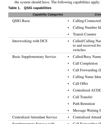
QSIG . . . 360
QSIG Basic Call Setup . . . . 361
QSIG Basic Supplementary Services . . . . 361
QSIG Centralized Attendant Services . . . . 366
QSIG Supplementary Services with Rerouting . . . . 367
QSIG Transfer into Lucent QSIG Voice Mail . . . . 368
QSIG Value-Added Lucent (VALU) . . . . 368
QSIG Protocols . . . . 369
Temporary Signaling Connection (TSCs) . . . . 369
Setting Up QSIG . . . . 371
QSIG Interactions . . . . 379
Centralized Voice Mail Via Mode Code . . . 395
Configuration requirements . . . . 395
Feature Support. . . . 396
Setting Up Centralized Voice Mail Via Mode Code . . . . 397
Japan TTC Q931-a Private Networking Protocols . . . 400
Overview . . . . 400
TTC Basic Call Setup with Number Identification Supplementary Service . . . . 400
TTC Q931-a Protocols . . . . 401
Setting Up TTC Q931-a . . . . 402
Appendix C: Security Issues
403
Network Security Issues . . . 403Overview . . . . 403
Appendix D: Capacities and Performance
407
Capacities and Resource Requirements . . . . 407Performance . . . . 409
Appendix E: C-LAN Installation
413
Overview . . . . 413Install the C-LAN Circuit Pack . . . . 414
Other Hardware Upgrades . . . . 416
Appendix F:
IP Trunk Installation and Administration
417
IP Trunk Installation . . . 417IP Trunk Administration . . . 418
Prerequisites . . . . 418
Administration overview . . . . 418
Plan call routing . . . . 419
DEFINITY administration procedures . . . . 421
Backing up configuration manager . . . . 425
Restoring IP trunk . . . . 425
Confirming the number of available ports . . . . 426
NT administration procedures . . . . 426
Procedures for Extension Dialing Between Sites . . . 433
Contents
DCS over IP Trunk . . . 435
DCS or Dedicated Trunks to Specific Locations Configurations . . . 436
Rerouting calls when IP transmission quality is poor . . . 439
Placing a test telephone call . . . 440
Setting up alerts on IP trunks . . . 440
Alert types . . . . 442
Viewing error messages . . . 442
Troubleshooting IP trunk . . . 443
Maintaining the performance of the IP trunk server . . . 444
Configuring Microsoft NetMeeting™ on a PC . . . 445
IP Trunk Worksheets . . . .449
Appendix G: References
459
Basic DEFINITY ECS documents . . . 459Call center documents . . . 462
Application-specific documents . . . . 463
Glossary
465
Preface
This book describes how to administer connections between DEFINITY® ECS switches (csi, si, and r models). The main focus is on TCP/IP for DCS signaling, introduced with DEFINITY Release 7, and H.323 trunks, introduced with DEFINITY Releases 8.
Purpose
This document provides the information needed to understand and administer the connections between DEFINITY ECS systems in a network using IP connections. It does not cover the installation or upgrade procedures for establishing physical connectivity between DEFINITY switches or for connecting the CMS and Intuity AUDIX adjuncts to a DEFINITY switch — that information is contained in the upgrades and installation documents listed in the References section.
Audience
This document is intended for anyone involved in planning, designing, or administering DEFINITY ECS systems as part of networks using IP connectivity.
Issue Status
First issued for DEFINITY ECS Release 7, this update includes Release 8 new hardware and administration, as described below.
IP Interface assembly The Release 8 IP Interface assembly is a 3-slot wide TN802B circuit pack. It enables the transmission of voice and signaling data over IP connections. It can be used in one of two operating modes:
• MedPro mode — enables H.323 tie trunks over IP connections
• IP trunk mode (as in Release 7) — enables emulation of DS1 trunks over IP connections.
Each IP Interface assembly operates in either Medpro mode or IP trunk mode for all trunks assigned to it — it cannot mix modes. The MedPro mode is the normal operating mode for R8 systems. The IP Trunk mode is used only for compatibility with existing R7 systems that cannot be upgraded to R8.
Issue Status
Preface
Screen Changes In Release 8, the following changes have been made to screens related to IP networks.
Ethernet Data Module screen
The ethernet Data Module screen is changed in Release 8.
1 The following fields have been removed from the ethernet Data Module screen: • Broadcast Address
• Automatic Subnet Routing
The Broadcast Address field previously enabled you to specify that broadcast messages are to be sent to a subset of the host’s subnet. Now, broadcast messages are always sent to the host’s full subnet.
The Automatic Subnet Routing field previously enabled you to disable automatic subnet routing. Now, automatic subnet routing is always enabled. 2 The following fields have been moved from the ethernet Data Module screen to
the new IP Interfaces screen: • Enable Link?
• Node Name • Subnet Mask
3 The following field is added to the ethernet Data Module screen: • Network uses 1’s for broadcast addresses?
This field enables you to accommodate systems on your network that use the older method of putting 0’s instead of 1’s in the host portion of a broadcast address.
add data-module next Page 1 of X
DATA MODULE
Data Extension: 2377 Name: __________________ Type: ethernet
Port: ________ Link: 2
Issue Status
Preface
ppp Data Module screen
The ppp Data Module screen is changed in Release 8.
The following fields have been added to the ppp Data Module screen: • Subnet Mask
The Mask field enables you to specify a subnetwork for the IP address of this node.
iP routing and the IP Route screen
The following fields have been added to the IP Routing screen: • Route Type — display only
For the display, change, and list IP Route commands, a display-only field, Route Type, indicates whether this IP route is a “host” or “network” route. Whether an IP route is a host or network route is determined by the
Destination Node IP address and the subnet mask associated with that address.
add data-module 1994
Page 1 of x DATA MODULE
Data Extension: 1994 Name: _ppp on link 4 to node 4___ BCC: 2 Type: ppp COS: 1
Port: 01c1502 COR: 1
Link: 4_ TN: 1 Enable Link? n
Node Name: ppp14_____ Subnet Mask: 255.255.255.0
Establish Connection: y
DESTINATION
Digits: 7241991_________ Node Name: ppp41___________ CHAP? n
add ip-route next Page 1 of 1
IP ROUTING
Route Number: 3
Destination Node: Gateway: C-LAN Board:
Issue Status
Preface
New Fields
In addition to the R8 screen changes described above, the following screens have new fields that specify IP trunk or IP Softphone parameters:
• Optional Parameter (System-Parameters Customer Options) • Trunk Groups
• Signaling Group • Station
• Several Status and Measurement screens
New Screens In Release 8, the following IP-related screens are new.
IP Interfaces screen
The IP Interfaces screen is new for Release 8.
The fields for this screen are described in Appendix A, “Screens Reference.”
IP Media Parameters
The IP Media Parameters screen specifies the type of codecs available for voice processing. The order in which you list the codecs is the order in which the system will use them. This screen also specifies the range of audio port numbers available.
change ip-interfaces Page 1 of 2
IP Interfaces
Inter-region IP connectivity allowed? n
Enable Net
Eth Pt Type Slot Code Sfx Node Name Subnet Mask Gateway Addr Rgn
n 255.255.255.0 . . .
n 255.255.255.0 . . .
n 255.255.255.0 . . .
n 255.255.255.0 . . .
change ip-parameters Page 1 of 1
IP Media Parameters
Audio Codec Preferences
1: G.711MU 2: G.723-6.3K
3: G.729A 4:
UDP Port Range
Issue Status
Preface
Reorganization The following chapter reorganization has been made for Release 8. • New Chapter 2 covers H.323 trunk administration.
• The previous Chapter 2 has been renamed Chapter 3. This chapter now describes how to connect switches and adjuncts using the C-LAN signaling connectivity — without the H.323 functionality — if you are running Release 8 software. This would be the case if you use R8 as a bugfix for R7 or if you are using the IP Interface board in IP Trunk mode.
Organization
Preface
Organization
This document is organized into four chapters and seven appendixes. Chapter 2 gives the essential information needed to administer H.323 trunk connections.
Chapter 1 – Overview
An overview of DEFINITY Connectivity and IP Addressing
Appendix C Security
A brief discussion of security issues as related to networking.
Chapter 2 –
H.323 Trunk Administration
Gives detailed procedures for initial administration of IP trunks using H.323 IP connections.
Appendix D –
Capacity and Performance
A brief discussion of network capacities and how to estimate C-LAN and voice-processing resources.
Chapter 3 –
C-LAN Administration
Gives detailed procedures for six basic network configurations using C-LAN IP connections.
Chapter 4 – Network Example
Shows administration screens for setting up a complex network.
Appendix A – Screens Reference
Field descriptions for network-related administration screens.
Appendix B – Private Networking
DCS features and QSIG.
Appendix E – C-LAN Installation
Installation procedures for the C-LAN circuit pack.
Appendix F–
IP Trunk Installation & Admin
Installation and initial administration for IP Trunk.
Appendix G– Document Reference
The DEFINITY documentation library.
Terminology
Preface
Terminology
The terms form, screen and node are used in this book with somewhat different meanings than in previous documents. The usage of the terms MedPro and IP Interface in this book deserve an explanation.
Screen The term “screen” is used in this book to mean what used to be called “form” — the set of switch-administration interface pictures that contain the fields that hold the switch-translations values. For example, the “Data Module screen.” Each screen can have one or more pages.
In some parts of this book, he terms “screen” and “form” are used interchangeably.
Node The term “node” has two meanings for DEFINITY ECS switches connected in a network. In a DCS network, node means a switch or adjunct. This is how the term is used on the Dial Plan screen for the field name, “Local Node Number.”
With TCP/IP connectivity, node has a different meaning — it refers to an interface to a network. For example, each of the 17 ports on the C-LAN board is a node in this sense. This is how the term is used on the Node Names, Data Module, Processor Channel, and IP Routing screens. This is also the common usage in a data networking environment. With these definitions, a “DCS node” (a switch) can have many “IP nodes,” (network interfaces).
In this book, node is used in the second sense, as a network interface. A “DCS node” is referred to as a switch or, in Chapter 4, as a switch node.
IP Interface and MedPro The official name for the TN802B circuit pack is IP Interface assembly. It is a media processing circuit pack in a 3-slot wide assembly. It can be administered to operate in one of two modes — IP Trunk mode or MedPro mode.
How to access this book from the web
Preface
How to access this book from the web
If you have internet access, you can view and download the latest version of DEFINITY ECS Release 8.2 Administration for Network Connectivity. To view the book, you must have a copy of Adobe Acrobat Reader (www.adobe.com).
To access the latest version:
1 Access the Customer Self-Service Center web site at http://www.lucent.com/enterprise/selfservice 2 Click Information Resources.
3 Click ELMO
4 Enter your IL to access the library.
5 Enter 555-233-504 (the document number) to view the latest version of the book.
To access this book from within the Lucent intranet, go to www.prodpubs.lucent.com.
How to order more copies
Call: Lucent Technologies Publications Center Voice 1-800-457-1235
Fax 1-800-457-1764
International Voice 317-322-6416 International Fax 317-322-6699
Write: Lucent Technologies Publications Center 2855 N. Franklin Road, Indianapolis, IN 46219
Order: Document No. 555-233-504
Comcode 108678749, Issue 1, April 2000
Tell us what you think
Preface
Tell us what you think
Let us know what you like or don’t like about this book. Although we can’t respond personally to all your feedback, we promise we will read each response we receive. You can use the comment card at the back of the book or send us your feedback in your own format.
Write to us at: Lucent Technologies
Product Documentation Group Room 22-2H15
11900 North Pecos Street Denver, CO 80234 USA Fax to: 303-538-1741
Send email to: [email protected]
How to Order Books
In addition to this book, other description, installation and test, maintenance, and administration books are available. A complete list of DEFINITY books can be found in the Business Communications System Publications Catalog, 555-000-010.
This book and any other DEFINITY books can be ordered directly from the Lucent Technologies Business Communications System Publications Fulfillment Center at 1-317-322-6791 or toll free at 1-800-457-1235.
How to Comment on This Book
Lucent Technologies welcomes your feedback. Please fill out the reader comment card found at the front of this manual and return it. Your comments are of great value and help improve our documentation.
Where to Call for Technical Support
Preface
Where to Call for Technical Support
Use the telephone numbers in the following table for technical support.
Telephone Number
Streamlined Implementation (for missing equipment) 1-800-772-5409
USA/Canada Technical Service Center 1-800-248-1234
Technical Service Center (INADS Database Administration)
1-800-248-1111
Asia/Pacific Regional Support Center 65-872-8686
Western Europe/South Africa/Middle East 441-252-774-800
Business Communications Europe 441-252-391-789
Eastern/Central Europe 361-345-4334
International Technical Assistance Center (ITAC) 1-303-804-3777
Latin/Central America & Caribbean 1-303-804-3778
DEFINITY Helpline 1-800-225-7585
Lucent Technologies Toll Fraud Intervention 1-800-643-2353
Lucent Technologies Technical Service Center 1-800-242-2121
Trademarks
Preface
Trademarks
The following are trademarks or registered trademarks of Lucent Technologies: • 5ESS
™,
4ESS™
• AUDIX® • Callvisor® • Callmaster® • CentreVu™ • CONVERSANT® • DEFINITY® • DIMENSION® • INTUITY
™
• MERLIN® • VOICE POWER®
The following are trademarks or registered trademarks of AT&T: • ACCUNET®
• DATAPHONE®
• MEGACOM®
• MULTIQUEST® • TELESEER®
The following are trademarks or registered trademarks of other companies: • Acrobat® is a registered trademark of Adobe Systems Incorporated • MS-DOS® (registered trademark of the Microsoft Corporation)
• MULTIQUEST® (registered trademark of Telecommunications Service) • ProShare® (registered trademark of Intel Corporation)
1
Networking Overview
This chapter provides background information that will help you understand and use the information in the remainder of the book. There are two major sections in this chapter. The first section describes how DEFINITY ECS switches can be connected, with a focus on IP connectivity. The second section describes IP addressing and subnetting.
DEFINITY Switch Connectivity
This section describes the basic components of a network of DEFINITY switches and how voice and signaling data are transmitted between switches for the different types of switch connections. It also provides a summary of the administration procedures for connecting switches via an IP network (using the C-LAN and
TN802B-MedPro circuit packs).
Connectivity Overview
Why connect switches? DEFINITY switches can be connected in various ways for various reasons. The main motivation for connecting switches is to enable people within an enterprise to easily communicate with one another, regardless of their physical location or the particular communications server they are assigned to. Inter-switch connections also enable the sharing of communications resources such as messaging and Call Center services.
What kinds of connections are possible?
Trunks
Switches communicate with each other over trunk connections. There are several kinds of trunks — each kind provides a different set of services for the connection. Commonly used trunk types are (Central Office) CO trunks, which provide
connections to the public telephone network through a central office, and tie trunks, which provide connections between switches in a private network.
These and other common trunk types are described in DEFINITY ECS Administrator’s Guide, 555-233-506.
DEFINITY Switch Connectivity
1
Networking OverviewNetworks
When two or more switches are connected via tie trunks, they form a private network. There are two basic types of networks for Lucent switches:
• Main-satellite/tributary (MS/T) — A network of switches in which a main switch is fully functional and provides attendants and CO trunks for connected satellite switches. Tributary switches are connected to the main and may have their own attendant and CO trunks. The main switch may be connected to one or more Electronic tandem networks (ETNs).
• Electronic tandem network (ETN) — A wide-area network of switches in which a call can tandem through one or more switches on its way from the originating switch to the destination switch. ETNs have a uniform dial plan (UDP), automatic alternate routing (AAR), and automatic route selection (ARS).
AT&T provides a service called software-defined network (SDN) that allows you to build a private network through the AT&T public network facilities. An ETN can be combined with an SDN to form a hybrid (ETN/SDN) network.
The switches in MS/T or ETN networks need to be provisioned with special DEFINITY networking software packages.
DCS
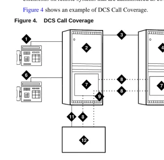
Distributed Communications System (DCS) is a messaging overlay for ETN or MS/T networks. The overlay provides signaling connections between network nodes that enable certain key call features to operate transparently across the DCS network. That is, the transparent features appear to operate as if the switches in the DCS network were a single switch. For example, the DCS Call Coverage feature enables calls to an extension on one switch to be covered by extensions on a remote switch in the network.
DCS consists of two components — routing and message signaling. Routing the message requires one of several networking software packages. Typically, UDP is used singe it is included with DCS at no additional charge.
Although DCS is actually a messaging overlay for an existing network, it is commonly thought of as a type of network itself. In this document, we will refer to DCS in this way — DCS network will refer to a cluster of switches that are part of an existing ETN or MS/T network and are also administered for DCS.
In addition to the normal tie-trunk connections for the transmission of voice and call-control data, DCS requires a special signaling connection to carry the information needed to make the DCS features work. This signaling connection, or link, between two switches in a DCS network can be implemented in one of three ways:
• over a processor interface (PI) channel (on the si model) or a packet gateway (PGATE) channel (r model) using the X.25 protocol
• over an ISDN-PRI D-channel (csi, si, or r models)
• over a TCP/IP (either PPP or 10Base-T Ethernet) connection (csi, si, or r models)
DEFINITY Switch Connectivity
1
Networking OverviewTCP/IP signaling connections were introduced with DEFINITY Release 7. Starting with R7, X.25 was no longer sold with new systems. R7 and later new systems ship with only TCP/IP connections or ISDN-PRI for DCS signaling. However, existing systems with X.25 and/or ISDN-PRI DCS signaling can be upgraded to the latest version and keep those signaling links, or a new system can be added to an existing DCS network. Connections to the CMS Call Center and Intuity AUDIX adjuncts can use either X.25 or 10Base-T DCS signaling.
When a DCS network uses a mixture of two or three of the different DCS signaling types, one or more switches in the network must act as a gateway. A gateway switch is connected between two switches using different signaling protocols and the gateway enables the two end switches to communicate by converting the signaling messages between the two protocols. A gateway switch can provide conversion between two or all three of the signaling protocols, but only one protocol can be used for DCS signaling between any two switches.
What is transmitted between connected switches?
A telephone call consists of voice (bearer) data and call-signaling data. If the call is over a DCS network, DCS signaling data is also required. The DCS signaling data is sent over a separate path from the voice and call-signaling data.
Call-signaling data
The call-signaling data includes messages necessary to set up the call connection, maintain the connection during the call, and remove the connection when the call is finished.
DCS-signaling data
The DCS-signaling data is separate from the call-signaling data. How it gets transmitted depends on the connection type, which determines the type of signaling protocol used.
How does the data move between switches?
DEFINITY Switch Connectivity
1
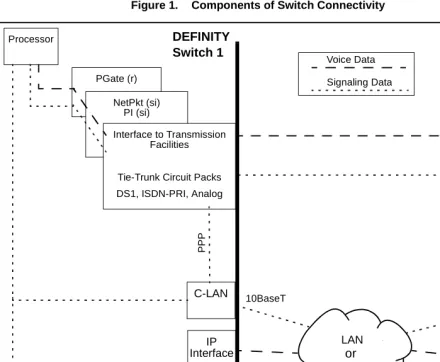
Networking OverviewFigure 1. Components of Switch Connectivity
What do the components do?
The function of each circuit pack shown in Figure 1 is described below.
Processor
The processor board is the main control element in handling the call. This is the UN332B for the r model, the TN 790B for the si model, and the TN798B for the csi model.
PGATE (r only)
On the r model, the PGATE board (TN577) connects the processor to the packet bus and terminates X.25 signaling.
NetPkt (si only)
The Network control/Packet Interface (NetPkt) board (TN794) replaces the NETCON (TN777B) and the PACCON (TN778) circuit packs in the R7si model. It also replaces the LAPD portion of the PI (TN765) circuit pack.
PGate (r)
NetPkt (si) PI (si)
C-LAN
Processor
Signaling Data
Interface to Transmission Facilities
Tie-Trunk Circuit Packs DS1, ISDN-PRI, Analog
C-LAN Tie Trunk Voice Data
WAN
PP
P
DEFINITY DEFINITY
Switch 2 Switch 1
IP Interface
MedPro mode
or
IP trunk mode
IP Interface
MedPro mode
or
IP trunk mode
LAN or
DEFINITY Switch Connectivity
1
Networking OverviewC-LAN
The C-LAN circuit pack (TN799B) enables signaling data to be transmitted via the TCP/IP protocols across a LAN or WAN. Signaling types include call setup and teardown, registration of IP softphones, TSCs, QSIG and DCS signaling.
The C-LAN circuit pack provides the data link interface between the switch processor and the transmission facilities. C-LAN prepares the signaling information for TCP/IP transmission over one of two pathways — either via an Ethernet LAN or a point to point protocol (PPP) connection — depending on how the data link is administered. If the link is administered for an ethernet connection, the signaling data is sent out on a 10Base-T network, which is connected directly to the C-LAN ethernet port. If the link is administered for a PPP connection, C-LAN inserts the signaling data on the TDM bus for subsequent inclusion (via the switching fabric) in the same DS1 bit stream as the voice transmissions.
The C-LAN board can be inserted in any available port slot. Up to 10 C-LAN boards can be used in the DEFINITY ECS R8r and R8si models — up to 2 C-LAN boards can be used in the R8csi model. Each C-LAN board has 17 ports; port 17 is used for the LAN interface and the other 16 can be used for PPP connections. Up to 508 sockets are available on each C-LAN circuit pack.
IP-Interface
The IP Interface circuit pack (TN802B) enables two switches to transmit voice data between them over an IP network. The TN802B normally operates in the MedPro mode, which enables support of applications that comply with the H.323-v2 protocols. It can also operate in the IP Trunk mode to support R7 IP trunks that emulate DS1 connections.
Tie-Trunk Circuit Packs
The tie-trunk circuit packs provide an interface between the switch and the transmission facilities for voice data, call-signaling data and data. See System Description, 555-230-211 for descriptions of tie-trunk (and other) circuit packs.
Pre-R7 circuit packs PI (si only)
The PRI functionality of the Processor Interface (PI) board (TN765) is replaced by the NetPkt board (TN794) in R7. The PI board will no longer be shipped with new systems starting with R7. The PI board is needed in switches upgraded to R7 and later releases only if existing X.25 connections are retained. The PI board has 4 data links that can connect to DS1 tie trunks over the TDM bus for interface to DCS or ISDN applications. The PI board terminates BX.25 and ISDN-PRI link access procedure on the D-Channel (LAPD).
NETCON (si only)
DEFINITY Switch Connectivity
1
Networking OverviewPACCON (si only)
The Packet Controller (PACCON) board (TN778) is replaced by the NetPkt board (TN794) starting in R7. For pre-R7 systems, PACCON provides an interface to the processor for D-Channel signaling over the packet bus.
The following table gives a summary of the different types of call connections and how the voice and signaling data are transmitted between switches.
For DCS+, X.25, and ppp connection types, the signaling and voice data are sent together over tie-trunk facilities as TDM-multiplexed frames. The DCS signaling data is sent as packets over a permanent virtual circuit (PVC) on tie-trunk facilities. For C-LAN Ethernet connections, the signaling and voice data are sent together over tie-trunk facilities as TDM-multiplexed frames. The DCS signaling data is sent as
Connection Type
Tie Trunk LAN or WAN Voice &
Call-Signaling
DCS
Signaling Voice
Call & DCS Signaling ISDN
(DCS+) & QSIG
T1/E1 facilities using ISDN-PRI or DS1 B-Channel
TSCs on the ISDN-PRI
D-Channel
TSCs on the ISDN-PRI
D-Channel
X.25
T1/E1 facilities using ISDN-PRI or DS1 B-Channel OR Analog trunk Packet PVC C-LAN PPP T1/E1 facilities using ISDN-PRI or DS1 B-Channel OR Analog trunk Packet PVC C-LAN Ethernet T1/E1 facilities using ISDN-PRI or DS1 B-Channel OR Analog trunk TCP Packet (DCS signaling only) IP Interface R7—DS1 emulation (IP Trunk mode) Packet PVC (X.25) RTP Packet (IP Interface in ip trunk mode) TCP Packet (C-LAN) IP Interface R8 — H.323
DEFINITY Switch Connectivity
1
Networking OverviewFor IP Trunk connections, the voice data is sent over IP facilities as RTP datagrams using the IP Interface assembly (TN802 or TN802B) — each packet can potentially take a different route through the network. The call and DCS signaling data are sent as datagram packets over an IP network using the C-LAN interface. The R7 type of IP trunk (IP Interface operating in ip trunk mode) can also use tie-trunk PVC facilities for the DCS signaling.
Release 8 Hardware Requirements
For the three DEFINITY ECS switch models — csi, si, and r — Release 8 IP trunking (H.323) and IP Softphone connections require at least one IP Interface (TN802B) circuit pack and at least one C-LAN (TN799B) circuit pack. DEFINITY One requires only the IP Interface circuit pack.
IP Interface The IP Interface assembly (J58890MA-1 L30) is a 3-slot wide TN802B circuit pack that provides voice processing over IP connections. The IP Interface assembly contains an NT processor, which is automatically administered by the DEFINITY software. The TN802B can be administered to operate in medpro mode for H.323 trunks and IP softphones, or in ip trunk mode for R7-type IP Trunk connections.
C-LAN The C-LAN circuit pack, TN799B, provides call setup, TSCs, QSIG, and DCS signaling over IP connections.
Note: The TN799B must be used to handle call signaling for the TN802B in MedPro mode. However, the previous version of C-LAN (TN799) can be used for call signaling with the TN802 or the TN802B operating in IP Trunk mode. The TN799 can also be used for DCS signaling connections on a switch that is using the TN802B in MedPro mode, as long as there are TN799Bs to handle the call signaling for the TN802B.
Hardware Requirements for Upgrades from Pre-R7 Switches
DEFINITY release 7 introduced several hardware changes that are also required for release 8. This section summarizes the hardware changes needed for pre-R7 switches upgrading to R8 for each switch model and each type of non-H.323 connectivity.
R8r model The following table shows the hardware required for an upgrade to an R8r.
Connection Type Hardware Required
BX.25 (Existing systems only)
PGATE (TN577)
TCP/IP
(ethernet and ppp)
C-LAN (TN799B)
DEFINITY Switch Connectivity
1
Networking OverviewR8si model The following table shows the hardware required for an upgrade to an R8si.
R8csi model The following table shows the hardware required for an upgrade to an R8csi.
Connection Type Hardware Required
BX.25 (Existing systems only)
• PI (TN765)
• NetPkt (TN794) — replaces the NetCon (TN777B) and the PACCON (TN778) circuit packs
• Upgraded processor (TN790B)
• In duplicated systems, a second NetPkt Control Assembly and a new DUPINT (TN792) TCP/IP
(ethernet and ppp)
• C-LAN (TN799B)
• NetPkt (TN794) — replaces the NetCon (TN777B) and the PACCON (TN778) circuit packs
• Upgraded processor (TN790B)
• In duplicated systems, a second NetPkt Control Assembly and a new DUPINT (TN792)
• Expansion Interface (TN570) if there is an EPN and there are packet-based applications (such as TCP/IP over the C-LAN or ISDN-PRI over the TN464). The TN776 EI can be used only when the switch has no packet-based applications.
ISDN-PRI • NetPkt (TN794) — replaces the NetCon (TN777B) and the PACCON (TN778) circuit packs
• Upgraded processor (TN790B)
• In duplicated systems, a second NetPkt Control Assembly and a new DUPINT (TN792)
• Expansion Interface (TN570) if there is an EPN. ISDN-PRI capabilities formerly provided by the PI and PACCON circuit packs are now provided by the NetPkt. Note that you do not need to replace the TN767 with the TN464 since NetPkt supports D-channel signaling over the TDM bus.
Connection Type Hardware Required
BX.25 (Existing systems only)
The csi model does not support BX.25 connectivity.
TCP/IP
(ethernet and ppp)
• C-LAN (TN799B)
• Upgraded processor (TN798B)
DEFINITY Switch Connectivity
1
Networking OverviewDEFINITY Connection types and capacities
This subsection gives an overview of the types of connections that can be set up with DEFINITY switches and adjuncts and capacities for some connectivity parameters.
Types of connections This table lists the types of connections possible with each DEFINITY model and adjunct.
If an R8 switch is connected to two endpoints by different connection types, it acts as a gateway (protocol converter) between the endpoints.
DEFINITY ECS
R8 Model Connection Type Endpoint
R8csi
Ethernet DCS, CMS, Intuity AUDIX
Synchronous PPP DCS
ISDN-PRI DCS+
H.323 Trunk DCS+
R8si
Ethernet DCS, CMS, Intuity AUDIX
Synchronous PPP DCS
ISDN-PRI DCS+
BX.25 DCS, CMS, Intuity AUDIX,
DEFINITY AUDIX
H.323 Trunk DCS+
R8r
Ethernet DCS, CMS, Intuity AUDIX
Synchronous PPP DCS
ISDN-PRI DCS+
BX.25 DCS, CMS, Intuity AUDIX,
DEFINITY AUDIX
DEFINITY Switch Connectivity
1
Networking OverviewDEFINITY Capacities The following table shows maximum allowable values and ranges for several connectivity parameters for DEFINITY ECS Release 8. Note that some or all maxima may not be achievable, depending on specific switch/traffic configurations.
csi si r
Circuit Packs*
* Circuit pack abbreviations: C-LAN: Control LAN (TN799B)
NetPkt: Network Control/Packet Interface (TN794)
PI: Processor Interface (TN765; used only for X.25 connections retained from pre-R7 systems) PGATE: Packet Gateway (TN577)
IP-Interface: Used in the Medpro mode (TN802B) 2 C-LAN
X IP-Interface (medpro)
10 C-LAN 1 NetPkt 2 PI
14 IP-Interface (medpro)
10 C-LAN 4 PGATE
46 IP-Interface (medpro)
Audio Streams per IP-Interface board†
† The number of audio streams per board is 22 if only one call uses a compression codec, even if all other calls use the G711.
31 for G711 codec 22 for compression codecs
31 for G711 codec 22 for compression codecs
31 for G711 codec 22 for compression codecs
H.323 IP Trunks + IP Stations
300 300 1000
Processor Channels: X.25 ethernet/ppp na 1–128 1–64 1–256 1–128 1–384 Interface Channels (listen ports): X.25 ethernet/ppp na 5000–64,500 1–64 5000–64,500 1–64 5000–64,500 ISDN-TSC Gateway Channels
na 128 256
Links per System 25 25 33
Links per Circuit Pack: PI PGATE C-LAN na na
1 ethernet, 16 ppp 4 na
1 ethernet, 16 ppp
na 4
1 ethernet, 16 ppp
IP Routes 270 400 650
Hop Channels (X.25 only)
IP Softphones
1
Networking OverviewIP Softphones
This book focuses on administration for the trunk side of the DEFINITY IP Solutions offer. The administration of the line side (IP Softphones) is covered in DEFINITY ECS R8 Administrator’s Guide, 555-233-506. For completeness, a brief checklist of IP Softphone administration is presented here.
For R8, there are two main types of DEFINITY IP Softphone applications — the telecommuter application and the road-warrior application. The CentreVu IP Agent is a variation of the telecommuter application.
Telecommuter application
The telecommuter application uses two connections to the DEFINITY system: a connection to the PC over the IP network and a connection to the telephone over the PSTN. The user places and receives calls with the DEFINITY IP Softphone interface running on a PC and uses the telephone handset to speak and listen.
To administer a telecommuter application, you must complete these steps:
1 Verify that the DEFINITY system is enabled for IP Softphone use. On the System Parameters Customer Options screen, verify that:
~ Maximum H.323 Stations is > 0 ~ Maximum IP Softphones is > 0 ~ IP Stations is y
2 Add a DCP station (or change an existing DCP station) using the Station screen: ~ Type [enter the phone model you wish to use, such as 6408D]
~ Port: x if virtual, or the port number of an existing phone ~ Security Code: [enter the user’s password]
~ IP Softphone: y
~ Go to page 2; Service Link Mode: as-needed 3 Install the IP Softphone software on the user’s PC
Road-warrior application
The road-warrior application uses two separate software applications running on a PC that is connected to a DEFINITY system over an IP network. The single network connection carries two channels: one for call control signaling and one for voice. DEFINITY IP Softphone software handles the call signaling and an H.323
V2-compliant audio application (such as Microsoft NetMeeting) handles the voice communications.
To administer a road-warrior application, you must complete these steps:
1 Verify that the DEFINITY system is enabled for IP Softphone use. On the System Parameters Customer Options screen, verify that:
~ Maximum H.323 Stations is > 0 ~ Maximum IP Softphones is > 0 ~ IP Stations is y
2 On the DEFINITY system, add an H.323 station using the Station screen: ~ Type H.322
IP Softphones
1
Networking Overview3 Add a DCP station (or change an existing DCP station) using the Station screen: ~ Type [enter the phone model you wish to use, such as 6408D]
~ Port: x if virtual, or the port number of an existing phone ~ Security Code: [enter the user’s password]
~ Media Complex Ext: [enter the extension of the H.323 station from the previous step]
~ IP Softphone: y
~ Go to page 2; Service Link Mode: as-needed 4 Install the IP Softphone software on the user’s PC
IP Addressing
1
Networking OverviewIP Addressing
This section describes IP addressing, subnetting, and routing.
Physical Addressing
The Address Resolution Protocol (ARP) software on the C-LAN circuit pack relates the 32-bit logical IP address, which is configured in software, with the 48-bit physical address of the C-LAN circuit pack, which is burned into the board at the factory. The C-LAN board has an ARP table that associates the IP addresses with the hardware addresses, which are used to route messages across the network. Each C-LAN board has one physical address and up to 17 assigned IP addresses (one for each port).
Logical Addressing
An IP address is a software-defined 32-bit binary number that identifies a network node. The IP address has two main parts -- the first n bits specify a “network ID” and the remaining 32 – n bits specify a “host ID.”
Format
Dotted Decimal notation
The 32-bit binary IP address is what the computer understands. For human use, the address is typically expressed in dotted decimal notation — the 32 bits are grouped into four 8-bit octets (bytes) and converted to decimal numbers separated by decimal points, as in the example below.
The eight binary bits in each octet can be combined to represent decimal numbers ranging from 0 to 255.
Class
Type Network ID Host ID
n 32 – n
Octet 1 11000010
Octet 2 00001101
Octet 3 11011011
Octet 4 00000111
IP Addressing
1
Networking OverviewConversion between binary and decimal
Conversion from binary to decimal notation is accomplished by adding the powers of 2 corresponding to the 1’s positions in each byte:
IP Address Classes The IP address space (232 or about 4.3 billion addresses) has been divided into five groups, Classes A–E, to accommodate the need for different network sizes. Each class has a different allocation of bits between the network and host IDs. The classes are identified by a fixed pattern of leading bits.
In Class A addresses, the first (leftmost) bit is always 0. So Class A IP addresses have 7 bits to define network IDs; 7 bits can define a total of 128 (0-->127) Class A networks. The remaining 24 bits of a Class A IP address are used to define host IDs. So for each of the 126 networks, there are 224 or 16,777,216 possible hosts.
The following table shows how IP addresses are the allocated among the five classes.
Address classes A, B, and C cover 87.5% of the address space. These addresses are assigned by the ISP or the Internet Assigned Number Authority (IANA) to
organizations for their exclusive use. The remaining 12.5% of addresses, designated classes D and E, are reserved for special purposes.
27 = 128
26 = 64
25 = 32
24 = 16
23 = 8
22 = 4
21 = 2
20 = 1
194 = 1 1 0 0 0 0 1 0
13 = 0 0 0 0 1 1 0 1
219 = 1 1 0 1 1 0 1 1
7 = 0 0 0 0 0 1 1 1
Class A
50% 0 Network ID Host ID
Class B
25% 1 0 Network ID Host ID
Class C
12.5% 1 1 0 Network ID Host ID
Class D
6.5% 1 1 1 0 Reserved for Multicast addresses
Class E
6.5% 1 1 1 1 Reserved for future use
IP Addressing
1
Networking OverviewThe IANA assigns a network address to an organization and a network administrator in the organization assigns the Host IDs associated with that Network ID to nodes within the organization’s network.
The following table shows the ranges of network and host IDs, and the total number of IP addresses (# network IDs times # host IDs), for each class.
You can tell the class of an IP address by the first octet. For example, 191.221.30.101 is a Class B address and 192.221.30.101 is a Class C address.
Private IP Address Addresses on the Internet need to be unique to avoid ambiguity in message routing over the Internet. To insure uniqueness, the Internet Assigned Number Authority (IANA) controls the use of IP addresses. Organizations that maintain private networks that never communicate with the Internet can use arbitrary IP addresses as long as they are unique within the private network. To help prevent the duplication of IP addresses on the Internet, the IANA has reserved the following ranges of IP addresses for private networks:
1 Class A networks: 16.6 Million addresses: 10.0.0.0 --> 10.255.255.255 16 Class B networks: 1 Million addresses: 172.16.0.0 --> 172.31.255.255 256 Class C networks: 65,000 addresses:192.168.0.0 --> 192.168.255.255
These IP addresses can be used repeatedly in separate private networks, which are not connected to the Internet. Routing tables prohibit the propagation of these addresses over the Internet. (See RFC 1918). All other IP addresses are unique and must be assigned by the IANA or ISP.
Network ID Range Host ID Range Total IP Addresses
Class A 7 bits
126 Networks:
1 to 126
24 bits
16.8 Million Hosts per network:
0.0.1 to 255.255.254
2.1 Billion 50%
Class B 14 bits,
16,382 Networks:
128.0 to 191.255
16 bits
65,534 Hosts per network
0.1 to 255.254
1.1 Billion 25%
Class C 21 bits,
2.1 Million Networks:
192.0.0 to 233.255.255
8 bits
254 Hosts per network:
1 to 254
0.5 Billion 12.5%
Classes D&E
IP Addressing
1
Networking OverviewSubnetting
Subnetting is the grouping of IP addresses associated with a network ID into two or more subnetworks. The subnets of a network ID are visible only within the
organization that owns the network ID; Internet routers route messages based on the network ID and the routers within the private organization differentiate between the individual subnets.
Reasons for subnetting Subnetting is desirable because it enables a more efficient allocation and management of IP addresses.
The three-class hierarchy of IP addresses results in an inefficient allocation of addresses in many cases because addresses are assigned and managed in blocks by network ID. For example, a company that needs 10,000 IP addresses in each of two locations might be assigned two Class B network IDs, each of which provides 65,534 IP addresses. Even though one Class B network ID would provide more than enough addresses for both locations, having a separate network ID for each location is easier to manage. If the company uses only 20,000 of these addresses, about 100,000 go unused.
In this case, subnetting would enable the company to use one Class B network ID and subdivide the addresses into two subnets, one for each location. Each subnet would have a unique “extended network ID” that would enable them to be managed as if they had unique network IDs.
Typically, organizations need to manage IP addresses in separate groups based on several criteria in addition to location:
• different types of LANs • different server applications • different work projects • security
The grouping of IP addresses provided by the three-Class structure does not allow nearly enough flexibility to meet the needs of most organizations. Subnetting allows the N IP addresses associated with a network ID to be divided into as few as 2 groups, each with N/2 addresses, or into as many as N/2 groups, each with 2 addresses, if desired.
How subnets are created
IP Addressing
1
Networking OverviewThe extended network prefix is then treated as a normal network ID. The remaining host ID bits define the host IDs within each subnet. For example, a block of IP addresses could be subdivided into four subnets by using 2 host bits to “extend” the network ID. Now there are 4 times as many (extended) networks and 1/4 as many hosts per network.
Note: In adding up the number of network and host IDs, certain addresses cannot be counted. In general, addresses with all ones or all zeros in either the network portion or the host portion of the address are not usable. These are reserved for special uses, such as broadcasting or loopback.
Subnet Masks Routing protocols use a subnet mask to determine the boundary between the extended network ID and the host ID in an IP address. The subnet mask is a 32-bit binary number consisting of a string of contiguous 1’s followed by a string of contiguous 0’s. The 1’s part corresponds to the extended network prefix and the 0’s part corresponds to the host ID of the address.
Each of the three classes of addresses has a default subnet mask that specifies the end of the 1st, 2nd, and 3rd octet as the boundary between the extended network prefix and the host ID. The default subnet mask in each case means “no subnetting.”
In addition to the default subnet masks, which divide the network and host IDs at the octet boundaries in the IP address, subnets can be formed by using 2 or more bits from the host octets to define the subnet ID.
Two-level classful hierarchy
Three-level subnet hierarchy
Subnet mask
Class
Type Network ID Host ID
Class
Type Network ID Subnet ID Host ID
1 1 1 1 1 1 1 1 1 1 1 1 1 1 1 1 1 1 1 . . . 1 0 0 0 0 0 . . . 0
Extended Network Prefix
Default Subnet Mask
Class A 11111111.00000000.00000000.00000000 255.0.0.0
Class B 11111111.11111111.00000000.00000000 255.255.0.0
IP Addressing
1
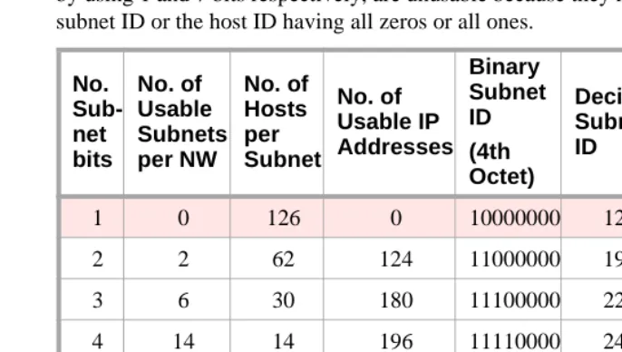
Networking OverviewClass-C subnets The following table shows that Class-C IP addresses can have 5 subnetting schemes, each with a different number of subnets per network. The first and last subnet, formed by using 1 and 7 bits respectively, are unusable because they result in either the subnet ID or the host ID having all zeros or all ones.
3-bit subnets
As an example, the third row of the table shows the results of using 3 bits for the subnet ID. Three bits are “borrowed” from the host ID leaving 5 bits for the host IDs. The number of subnets that can be defined with three bits is 23 = 8 (000, 001, 010, 011, 100, 101, 110, 111). Of these, only 6 are usable (all ones and all zeros are not usable). The remaining 5 bits are used for the host IDs. Of these, 25 – 2 = 30 are usable. As shown in columns 2–4 (row 3), by using 3 bits for subnetting, a Class C network can be divided into 6 subnets with 30 host IDs in each subnet for a total of 6 X 30 = 180 usable IP addresses.
Subnet mask
The subnet mask is defined as follows. The subnet bits “borrowed” from the host ID are the highest-order bits in the octet of the host ID. The 5th and 6th columns of the table show the binary and decimal subnet IDs, formed by using the subnet bits as the highest-order bits in an octet. For example, in the third row of the table, the binary bit pattern is 11100000, which is decimal 224. This is the highest number that can be formed with the 3 high-order bits in the octet. The subnet mask is formed by putting this number in the 4th octet of the default subnet mask (shown in the last column of the table).
The mask, 255.255.255.224, corresponds to a bit pattern of 27 ones followed by 5 zeros. This mask would be used to check that two IP addresses are on the same or different subnets by comparing the first 27 binary digits of the two addresses. If the first 27 binary digits are the same, the two addresses are on the same subnet.
No. Sub-net bits No. of Usable Subnets per NW No. of Hosts per Subnet No. of Usable IP Addresses Binary Subnet ID (4th Octet) Decimal Subnet ID Class C Subnet Masks
1 0 126 0 10000000 128 255.255.255.128
2 2 62 124 11000000 192 255.255.255.192
3 6 30 180 11100000 224 255.255.255.224
4 14 14 196 11110000 240 225.225.225.240
5 30 6 180 11111000 248 255.255.255.248
6 62 2 124 11111100 252 255.255.255.252
IP Addressing
1
Networking OverviewExample
To continue the example using a 3-bit subnet ID, assume a Class C network ID of 192.168.50.xxx. This network ID can provide 254 usable IP addresses, all on the same network — from 192.168.50.1 to 192.168.50.254. If we divide this network into 3-bit subnets, we will have 6 usable subnets with 30 usable IP addresses in each subnet. Note that we have lost 74 usable IP addresses in the process because we had to discard the all-ones and all-zeros subnet IDs (62 addresses) and host IDs (12 addresses). There is always a loss of usable IP addresses with subnetting.
The following table shows the subnet boundaries for the six subnets formed with 3 bits. The boundaries are the numbers formed by using all combinations of 3 bits as the highest-order bits in an octet (Columns 1 and 2) and then using these numbers in the 4th octet for the host IDs.
For example, the IP addresses 192.168.50.75 and 192.168.50.91 are on the same subnet but 192.168.50.100 is on a different subnet. This is illustrated in the following diagram where the subnet mask, 255.255.255.244 is used to compare the first 27 binary digits or each address.
Binary Subnet Boundaries (for 3 bits)
Decimal Subnet Boundaries
Range of usable IP Addresses in the Subnet
00000000 0 not usable
00100000 32 192.168.50.33 to
192.168.50.62
01000000 64 192.168.50.65 to
192.168.50.94
01100000 96 192.168.50.97 to
192.168.50.126
10000000 128 192.168.50.129 to
192.168.50.158
10100000 160 192.168.50.161 to
192.168.50.190
11000000 192 192.168.50.193 to
192.168.50.222
IP Addressing
1
Networking OverviewThe other four possible subnetting schemes for Class C addresses, using 2, 4, 5, and 6 subnet bits, are formed in the same way. Which of the 5 subnetting schemes to use depends on the requirements for the number of subnets and the number of hosts per subnet.
Class-A and Class-B subnets
For Class A and Class B IP addresses, subnets can be formed in the same way as for Class C addresses. The only difference is that many more subnets per network can be formed. For Class B networks, subnets can be formed using from 2 to 14 bits from the 3rd and 4th octets. For Class A networks, subnets can be formed using from 2 to 22 bits from the 2nd, 3rd and 4th octets.
The Subnet Mask field on the ppp Data Module screen (used for ppp connections) and on the IP Interfaces screen (used for ethernet connections) enables the specification of a subnet for the IP address.
Subnet mask
11000000 10101000 00110010 01001011
11000000 10101000 00110010 01011011
11000000 10101000 00110010 01100100
11111111 11111111 11111111 11100000
192 168 50 75
192 168 50 91
192 168 50 100
255 255 255 224
IP Addressing
1
Networking OverviewValid subnet masks The valid subnets for each Class of address are:
Notice that all 5 valid Class C subnet masks can also be valid Class B or Class A subnet masks, and all 13 valid Class B subnet masks can also be valid Class A subnet masks.
For example, 255.255.255.224 is a valid subnet mask for all three address classes. It allows 6 (23−2) subnetworks for Class C addresses, 2046 (211−2) subnetworks for Class B addresses and 524,286 (219−2)subnetworks for Class A addresses. Each of these subnetworks can have 30 (25−2) hosts.
Class A
(default 255.0.0.0)
Class B:
(default 255.255.0.0)
Class C
(default 255.255.255.0)
255.192.0.0 255.255.192.0 255.255.255.192
255.224.0.0 255.255.224.0 255.255.255.224
255.240.0.0 255.255.240.0 255.255.255.240
255.248.0.0 255.255.248.0 255.255.255.248
255.252.0.0 255.255.252.0 255.255.255.252
255.254.0.0 255.255.254.0
255.255.0.0 255.255.255.0
255.255.128.0 255.255.255.128
255.255.192.0 255.255.255.192
255.255.224.0 255.255.255.224
255.255.240.0 255.255.255.240
255.255.248.0 255.255.255.248
255.255.252.0 255.255.255.252
255.255.254.0
255.255.255.0
255.255.255.128
255.255.255.192
255.255.255.224
255.255.255.240
255.255.255.248
IP Addressing
1
Networking OverviewDefault Gateway
On LANs that connect to other networks or subnetworks, it is convenient to define a default gateway node. The default gateway node is usually a router that is connected to 2 or more different (sub)networks. It could also be a C-LAN ethernet port that is connected to other C-LANs on the same switch. Any packets addressed to a different (sub)network, and for which no explicit IP route is defined, are sent to the default gateway node. The default gateway node is either directly connected to the addressed node or knows of another router that knows how to get to the packet address.
A default gateway can be assigned to a node (C-LAN port or IP Interface port) on the IP Interfaces screen. If you do not assign a default gateway to a node, an explicit host IP route must be defined to enable communications to any node on a different (sub)network.
You can also assign a default gateway by setting up an IP route with the default node as the destination and the router (or C-LAN) as the gateway. The default node is a display-only entry on the Node Names screen with IP address 0.0.0.0. It acts as a variable that takes on unknown addresses as values. When the “default” IP route is set up, any address not know by C-LAN is substituted for the default address in the default IP route, which uses the router as the “default” gateway.
!