ANALYSIS FOR THE VIBRATION BEHAVIOR OF A CANDU FUEL CHANNEL
UNDER NORMAL AND ABNORMAL SUPPORT CONDITIONS
Jin-Ho Park1, Doo-Byung Yoon2, Young-Chul Choi2, Chang-Gi An3
1
Head, Advanced Condition Monitoring & Diagnostics Laboratory, Korea Atomic Energy Research Institute (KAERI), Daejeon City, Korea (E-mail: [email protected])
2
Senior Researcher, Advanced Condition Monitoring & Diagnostics Laboratory, Korea Atomic Energy Research Institute, Daejeon City, Korea
3General Manager, Shinhwa Technology, Daejeon City, Korea
ABSTRACT
Three dimensional finite element modal model of a CANDU fuel channel has been developed and the free and forced vibration analyses implemented under the assumed fault conditions such as a loss of the garter spring stiffness, the abnormal support of the end fittings, migration of the garter springs, etc. The first three natural frequencies for the fuel channel model were found to be 5.58, 15.23, and 29.6 Hz. They showed comparable to the measured data, which have been obtained from the reactor noise analyses by using stationary In Core Flux Detector (ICFD) noise signals. A loss of the garter spring stiffness and a failure of the end fitting support cause the above natural frequencies to shift to lower values than in the normal case. Moreover, in most fault cases, an additional peak frequency component was found besides the three natural frequencies. It has been concluded that the vibration frequency response spectra of the fuel channel give a useful means to monitor the structural integrity of a fuel channel assembly at an early stage.
KEYWORDS: CANDU, Fuel Channel, Vibration, Garter Spring, Finite Element Analysis, Natural Frequencies, Normal Condition, Abnormal Condition
1. INTRODUCTION
expected to occur.
The objective of this study is to develop a three dimensional (3D) finite element modal model of a CANDU fuel channel and to investigate changes in its vibration spectral characteristics in the case of abnormal conditions such as end fitting support and non-contact and movement of the garter springs.
2. MODELING OF FUEL CHANNEL
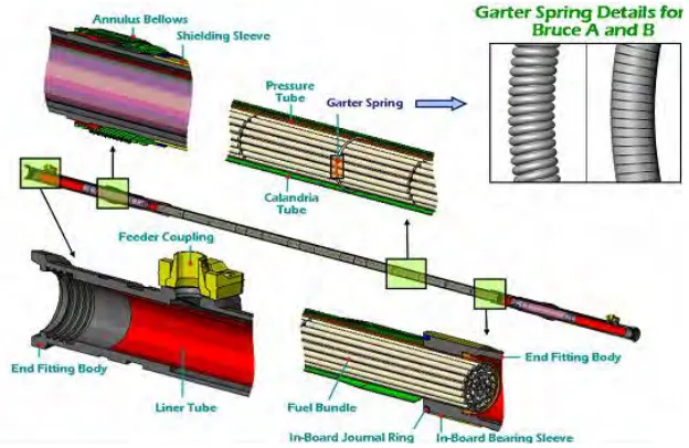
In order to perform a detailed finite element modeling of a CANDU fuel channel, a simplified three dimensional solid model was developed based on a fuel channel assembly configuration. Figure 1 shows a typical CANDU fuel channel assembly. As shown in Figure 1, a fuel channel assembly is typically comprised of the six major components such as fuel bundles, pressure tube, Calandria tube, garter springs, end fittings, and liner tubes. The 3D solid model of the fuel channel is depicted in Figure 2. The Solidworks[5] software package, which is a popular commercial package for Computer Aided Engineering (CAE), was used for 3D modeling.
A simplified 3D solid model is shown in Figure 3, in which the mass of the fuel bundles and of the coolant inside the pressure tube are assumed to be axially distributed along the inner surface of the tube. The hydrodynamic mass effect outside the Calandria tube is also reflected in the model. The closure plugs, shielding sleeves, and the shield plug are modeled as an additional mass attached to the body of the end fittings.
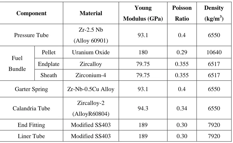
The material properties corresponding to the structural components are summarized in Table 1 . The properties are based on the temperature and pressure conditions under full power steady state o peration. In the case of the pressure tube, the temperature distribution is not constant along the coolan t flow direction since there exists a temperature difference between the reactor primary heat transport system inlet and outlet. Therefore, the recommended average values of the properties have been adopte d.
The 3D finite element model is depicted in Figure 4. The ANSYS, Version 9.0 software package[6] has been used for modeling and meshing of each component. The 4-node shell type element was used for the Calandria tube model, with a mesh of 24 elements in the circumferential direction and 74 elements in the axial direction. Heavy water around the Calandria tube is assumed to be a hydro-dynamically added mass to the tube mass based on reference[7]. It is assumed that both sides of the Calandria tube is fixed to the Calandria tube sheet since the Calandria tube sheet is much more rigid than the Calandria tube. The pressure tube is positioned coaxially inside the Calandria tube and contains fuel bundles (Figure 3). Therefore, the same type of shell element as for the Calandria tube is adopted, as shown in Figure 4, where 24 elements in the circumferential direction and 78 elements in the axial direction were used.
on the stiffness of the end fitting body. Thus their masses were uniformly added to their effective parts on the end fitting body in the axial direction. Similarly, 24 shell type elements in the circumferential direction and 24 elements in the axial direction were generated.
Table 1: Material Properties of Fuel Channel Components
Component Material Young
Modulus (GPa)
Poisson
Ratio
Density
(kg/m3)
Pressure Tube Zr-2.5 Nb
(Alloy 60901) 93.1 0.4 6550
Fuel Bundle
Pellet Uranium Oxide 180 0.29 10640
Endplate Zircalloy 79.75 0.355 6517
Sheath Zirconium-4 79.75 0.355 6517
Garter Spring Zr-Nb-0.5Cu Alloy 93.1 0.4 6550
Calandria Tube Zircalloy-2
(AlloyR60804) 94.3 0.34 6550
End Fitting Modified SS403 189 0.30 7920
Liner Tube Modified SS403 189 0.30 7920
Figure 2. Details of the 3D Model of a Fuel Channel Assembly
Figure 3. Simplified View of a Fuel Channel Section
The liner tube is located inside the end fitting body is modeled with the same type of element as that of the end fitting body. In other words, 24 of 4-node shell elements are used in the circumferential direction. It has been also assumed that it is axially coupled with the end fitting body and with the pressure tube.
It is almost impossible to analyze the dynamic characteristics of the fuel channel model combining a fully modeled garter spring, since the number of finite elements would tremendously high. For the relatively low vibration modes, the garter spring does react like a linear spring, in which both ends are supported radially by the pressure tube and by the Calandria tube. Thus the model is assumed to consist of 16 linear springs in total, uniformly distributed between the pressure tube and the Calandria tube, as shown in Figure 8. Both ends of the garter spring element are not always in contact (coupled) with the pressure tube and the Calandria tube, that is, non-contact phenomena could occur when vibrating laterally. Thus, a contact element (COMBINE 40 element) has been considered in this model.
The fuel bundle is assumed to be a one dimensional beam having the same dynamic characteristics as the 3D fuel bundle. The fluid between the pressure tube and Calandria tube both inside and outside the fuel channel has been treated as an added mass because the effect on the lower mode bending vibrations by the fluid stiffness effect is small.
The total of 3,488 elements and 6,288 nodes have been incorporated in this model.
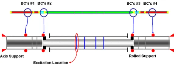
The boundary conditions are illustrated in Figure 5. The end fittings are supported by the inboard and outboard journal bearings within the lattice tubes; therefore, rolled support boundary conditions are imposed on the positions. The pressure tube and the liner tube are coupled in the radial direction, and so are the end fitting body and the liner tube. The pressure tube and the liner tube are axially coupled, and the end shield plug is constrained along the axial direction.
Figure 5. Boundary Conditions
3. MODAL ANALYSIS
modes, are seen in Figure 6. The analysis results show comparable to the measured data in the case of a similar fuel channel, which were obtained using the ICFD noise analyses, as reported in [8]. Therefore, the fuel channel model developed here can be used for the prediction of the behavior due to coolant flow or to feeder pipe vibrations. The next section describes application of the model to frequency response analysis.
(a) 1st Mode
(b) 2nd Mode
(c) 3rd Mode (d) Measured ICFD noise spectra
Figure 6. Analyzed Natural Mode Shapes of Fuel Channel Assembly and Measured ICFD Noise Spectra
4. FORCED VIBRATION ANALYSES
The forced vibration analysis based on the modal model has been performed in order to assess changes in vibration characteristics due to various fault conditions which can affect the fuel channel natural frequencies. A total of 19 different cases, including the normal condition, have been analyzed, and the corresponding boundary conditions for each case are summarized in Table 2.
There are four categories of the fault scenarios, the first of which includes different types of end fitting support conditions (case 2 to case 5), the second is when there is no contact of the garter springs (case 6 to case 10), the third is the combined conditions (case 14 to case 17), which means t hat the first and the second cases occur simultaneously, and lastly five types of garter spring moveme nts (case 11 to case 13 and case 18 to case 19).
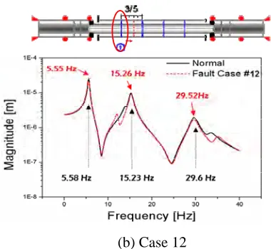
Since the main cause of the pressure tube excitation is thought to be flow-induced vibrations, it has been assumed that a random transverse force with amplitude of unity is applied at the pressure tube node to which the 1st (extreme left hand) garter spring is connected. The displacement Auto Power Spectral Density Functions (APSDs) of the model for two typical fault cases are compared to the normal case, respectively, as shown in Figure 7 (cases 2 and case 12) and the deviation of the first three peak (mode) frequencies corresponding to all of the assumed abnormal conditions are summarized in Table 3.
For the 1st mode frequency, case 11 (when the left inboard bearing support and all the garter springs failed) is the worst case. Case 12 (when the left outboard bearing support and all the garter springs failed) and case 11 are found to be the extreme cases for the 2nd and 3rd mode frequencies, respectively. What is interesting
Calandria Tube Pressure Tube
is that in most cases additional peak frequency component is coming out besides the existing three natural frequencies. Also, it has been confirmed that structural integrity and/ or mechanical abnormality of the fuel channel system can be detected at an early stage by monitoring frequency response spectra and vibration amplitude of the fuel channel.
(a) Case 2 (b) Case 12
Figure 7. Vibration Response Spectra
Table 2: Fault Scenarios Table 3: Variation in natural frequencies
End Fitting Body
Support
End Fitting Body Support Inlet Garter Spring Outlet Analysis Case Fuel Bundle Boundary 1 Boundary
2 #1 #2 #3 #4 Boundary
3 Boundary
4
1st ○ ○ ○ ○ ○ ○ ○ ○ ○
2nd ○ ○ ○ ○ ○ ○ ○ ○
3rd ○ ○ ○ ○ ○ ○ ○
4th ○ ○ ○ ○ ○ ○ ○ ○
5th ○ ○ ○ ○ ○ ○ ○
6th ○ ○ ○ ○ ○
7th ○ ○ ○ ○ ○ ○
8th ○ ○ ○ ○ ○ ○ ○
9th ○ ○ ○ ○ ○ ○ ○ ○
10th ○ ○ ○ ○ ○ ○ ○
11th ○ ○ ○ Move ○ ○ ○ ○ ○
12th ○ ○ ○ Move ○ ○ ○ ○ ○
13th ○ ○ ○ ○ Move Move ○ ○ ○
14th ○ ○ ○
15th ○ ○ ○ ○
16th ○ ○ ○ ○ ○ ○ ○ ○
17th ○ ○ ○ ○
18th ○ ○ ○ ○ Move ○ ○ ○
19th ○ Move ○ ○ Move ○ ○
5. CONCLUSIONS
The summary of this study is as follows:
1) The 3D finite element modal model of a CANDU fuel channel has been developed.
2) The first three natural frequencies of a normal fuel channel are estimated to be 5.58 Hz, 5.23 Hz, and 29.60 Hz, respectively.
3) It is found that vibration response spectra of a CANDU fuel channel can provide a useful means for detecting and diagnosing the abnormalities during plant operation.
ACKNOWLEDGEMENT
The authors are grateful to the staff of Plant Performance Section, Inspection and Maintenance Division, Ontario Power Generation for technical assistance and useful discussions.
REFERENCES
[1] J. A. Thie, “Power Reactor Noise,” American Nuclear Society, 1981.
[2] O. Glockler and M. V. Tulett, “Application of Reactor Noise Analysis in the CANDU Reactors of Ontario Hydro,” IMORN-25, U.S.A., 1994.
[3] Jin-Ho Park et al, “Identification of reactor internals' vibration modes of a Korean standard PWR using structural modeling and neutron noise analysis,” Progress in Nuclear Energy, Vol. 43, No. 1/4, pp. 177-186, 2004.
[4] O. Glockler and D. Cooke, “Noise Analysis Based Validation of the Dynamics of In-core Flux Detectors and Ion Chambers used in SDS and RRS Systems,” CNS meeting, 1996.
[5] Solidworks 2005 Professional, Solidworks Inc., 2005.
[6] ANSYS Version 10.0, Structural Analysis Guide Manual and Element Reference Manual, 2005.
[7] D.D. Derksen and B.A.W. Smith “Modeling of CANDU Fuel Channel Vibration to Support Neutron Flux Noise Analysis” ACEL, 1997.
[8] J. Fiedler et al, “Vibration Measurements in the Argentine CANDU Reactor Embalse by Use of Neutron Noise Analysis,” 7th SMORN, OECD, 1996.