150
Analysis of High Speed Rotating Turbine with Blade
Angle 25
0
Using CFD
Manish Vyas
1, Syed Muzaffaruddin
21,2Assistant Professor, Mechanical Engineering Department 1,2KG Reddy College of Engineering & Technology
Email: [email protected]1
Abstract – An attempt of study is made to understand the variation of minimum temperature, pressure, velocity
and entropy of high speed rotating turbine by using CFD with usage of two different fluids i.e., Oxygen and nitrogen. In our present research a model of turbine with blade angle 250 is created in Creo element/Pro-E by using the available data of blade profile which is later simulated in Ansys Fluent 14.5 by meshing the model, to specify the simulation settings and physical parameters required to describe the flow through turbo expander at inlet and to examining and analyzing the output results. The variation of parameters is indicated by plotting various graphs and by using this result we can analyze flow through expansion turbine.
Index Terms – Turbine, Blade angle 250, Pro-e, Ansys Fluent 14.5.
1. INTRODUCTION
In our current research, we are majorly focusing upon variation in properties of cryogenics liquids which are widely used in all areas manufacturing, medical, transportation, gas production, oil production and for refrigeration also. For production of this cryogenics liquids it will be done in high pressure plants but for the production low pressure liquids, cryogenic turboexpander is used which consist of compressor, nozzle, expander and exhaust. Here the cryogenic expander is a heart of turbo expander in this phase change will be taken care.
A rotating turbine is used as a turbo expander which is a pressure let-down device that produces low temperatures for the formation of cryogenics liquids this are majorly used in all areas of the gas and oil industries to produce cryogenic refrigeration. Liquefaction of gases is generally used in large scale transportation, storage and low temperature applications. For the production of cryogenic liquids like nitrogen, oxygen and argon in a large scale, cryogenic turbo expander provides the most prominent economical route. Cryogenic turbo expander has the high thermal efficiency and thermal reliability when compared to the high and medium pressure systems.
2. LITERATURE REVIEW
The major component of any cryogenic plant is turbine or the turbo expander. As the major role of turbo expander is to phase change from gas to cryogenics liquids by decreasing static temperature below the refrigeration point. This concept was first introduced by Lord Rayleigh in June 1898. He discussed regarding use of turbine as an expansion device in place of other expansion device. In 1898, a British engineer named Edgar C. Thrupppatenteda liquefying machine using an expansion turbine. A simple method sufficient for the design of a high
efficiency expansion turbine is outlined by Kun et. al [1-2].
Agahiet. al. [3-4] have explained the design process of the turboexpander utilizing modern technology, such as CFD software, Computer Numerical Control Technology and Holographic Techniques to further improve anal ready impressive turboexpander efficiency performance. Several characteristics values are used for defining significant performance criteria of turbo machines such as turbine velocity ratio, pressure ratio, flow coefficient factor and specific speed [5]. Balje has presented a simplified method for computing the efficiency of radial turbo machines and for calculating their characteristics [6]. The concept of specific speed was first introduced for classifying hydraulic machines. Balje [7] introduced this parameter in design of gas turbines and compressors. PhD dissertation of Ghosh [8] explains the detailed summary of technical features and experimental analysis of cryogenic turboexpander. S.K. Ghosh, R.K. Sahoo, S.K. Sarangi in 2005 gave a computational approach to the design of a cryogenic turbine blade profile [9].
3. COMPUTATIONAL FLUID FLOW
ANALYSIS
151
4. DESIGNING OF A TURBINE MODEL
Designing of model is done in Pro-E by using data available for blade profile, hub, and shroud. The hub and the tip streamlines are taken from the literature [8, 9]. The surface of turbine model which had generated is considered as the mean surface within a blade. The blade faces will be merged where they are tangent to one another. Here while developing the model there is a need to create a stage fluid zone body for the flow passage, Create fluid zone property is selected and an enclosure feature to subtract the blade body. This resulting enclosure can be used for a CFD analysis of the blade passage. Create all blades this property is used to create All the blades are created using create all blades property by specifying the number of blades in the Pro-E model. Here we are using ten numbers of blades.
In summary, the major dimensions for prototype turbine have been computed by S.K. Ghosh [8] as follows:
Rotational speed: N = 22910 rad/sec = 218790 rpm
Wheel diameter: D2 = 16.0 mm
Eye tip diameter: Dtip = 10.8mm
Eye hub diameter: Dhub = 4.6mm
Numbers of blades: Ztr = 10
[image:2.595.308.534.113.312.2]Thickness of blades: ttr = 0.6mm
Figure 1: Sample Model designed with using blade angle 250
[image:2.595.310.532.346.557.2]Figure 2: Inlet fluid passage
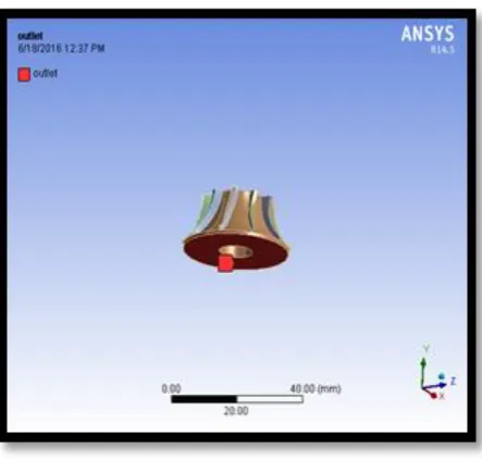
Figure 3: Outlet fluid passage
5. MATERIAL SELECTION
[image:2.595.73.279.503.708.2]As per the requirement the following material are used in concerned percentage for manufacturing of turbo expander which can sustain in the required condition.
Table 1: Percentage of materials used in turbo expander
Alloying Element Percentage (%)
Copper 0.1
Iron 0.6
Magnesium 0.4 – 1.4 Manganese 0.4 – 1.0
Chromium 0.3
152
Aluminum Rest
6. MESHING AND ITERATION
[image:3.595.307.528.108.350.2]Ansys fluent 14.5 is used for meshing of turbine model. High quality hexahedral meshes are created in rotating turbine rotor for fluid flow analysis. Geometry information regarding rotating turbine rotor is imported from Pro-e in IGES format. Ansys uses this pro-e file to the length unit, number of blades, axis of rotation and other parameters.
Figure 4: Meshed turbine model.
7. INPUT CONDITIONS FOR ROTATING
TURBINE SIMULATION
CFD simulation for rotating turbine is done in Ansys fluent 14.5. In this the model is taken from pro-e which is convpro-ertpro-ed from 2D to 3D and latpro-er it is meshed by fixing the nodes, in software general conditions are provide for pressure based and energy equation with fluid density and viscosity. In following figure, we can see the boundary conditions and fluid condition while inlet of the rotating turbine.
Mass flow rate=0.024 kg/sec Temperature: 120 K
Pressure= 30 bar
Here we are giving the no. of iteration is 20.
[image:3.595.74.293.239.435.2]Figure 5: Inlet condition for turbine in Ansys
Figure 6: Fluid conditions for nitrogen
[image:3.595.305.528.378.576.2] [image:3.595.306.527.599.748.2]153
8. OBTAINED RESULTS
Ansys fluent 14.5 is used to allow easy visualization and quantitative analysis of results of CFD simulations. It can create user defined scalar and vector variables it also includes automatic report.
WITH BLADE ANGLE = 250
WORKING FLUID = NITROGEN
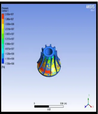
[image:4.595.307.503.110.290.2]8.1.1 Pressure
Figure 8: Result of pressure flow inside the turbine
[image:4.595.307.489.329.522.2]8.1.2 Velocity
Figure 9: Results of velocity flow inside the turbine
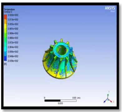
8.1.3 Temperature
Figure 10: Results of Temperature flow inside the turbine
8.1.4 Entropy
Figure 11: Results of Entropy flow inside the turbine
WITH BLADE ANGLE = 250
WORKING FLUID = OXYGEN
[image:4.595.72.264.485.668.2]154 Figure 12: Results of pressure flow inside the turbine
[image:5.595.306.480.111.282.2]8.2.2 Velocity
Figure 13: Results of velocity flow inside the turbine
8.2.3 Temperature
Figure 14: Results of Temperature flow inside the turbine
8.2.4 Entropy
Figure 15: Results of Entropy flow inside the turbine
9. RESULTS & DISCUSSION
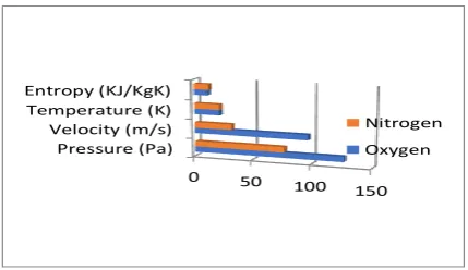
[image:5.595.74.239.356.541.2]Graph and table are available from generated results. In this the input parameters for nitrogen and oxygen fluid provided were same. the input pressure was 30bar but if we see the variation in output pressures, for oxygen fluid output pressure is directly double from the nitrogen fluid. Same in the case of output velocities in some extent we can say.
Table 2: Table for output results
Proper ties at blade angle 25o
Press ure (Pa)
Velocity( m/s)
Temper ature (K)
Entropy( kJ/kg K)
Nitrog
en 127 97 22 11.66
Oxyge
[image:5.595.302.534.653.770.2]155
0 50
100 150
Pressure (Pa) Velocity (m/s) Temperature (K) Entropy (KJ/KgK)
Nitrogen
[image:6.595.75.290.134.258.2]Oxygen
Figure 16: Graph shows variation in output results for nitrogen and oxygen
10.CONCLUSION
In this work, the flows analysis is done for rotating turbine of blade angle 250 to understand the variation in performance of turbine during the phase change process and output results when we are using two different fluids i.e., nitrogen and oxygen. Here this rotating turbine model is meshed and simulated for specified inlet conditions which describe the flow velocity, pressure and temperature. On the basis of these inlet parameters that we are analyzing, output results are obtained for which graphs will be drawn and variation is analyzed.
There is a lot of variation in results when fluid is change, for this again the redesigning of turbine model is necessary by changing its blade angle in future work the remodeling and analyzing of rotating turbine can be done by using different blade angle.
Acknowledgments
The authors acknowledge the support of KG Reddy College of Engineering & Technology.
(A.1)
REFERENCES
[1] L.C. Kun, T.C. Hanson, High efficiency turboexpander in aN2 liquefier AICHE Spring meeting, Houston, Texas (1985).
[2] L. C. Kun, Expansion turbines and refrigeration for gas separation and liquefaction Advances in Cryogenic Engineering (1987), V33, 963-973 [3] R. R. Aghai, M. C. Lin, B. Ershaghi, High
Performance cryogenic turboexpanders Advances in Cryogenic Engineering (1996), V41, 941-947 [4] R. R. Aghai, M. C. Lin, B. Ershaghi,
Improvements of the efficiency of the turboexpanders in cryogenic applications Advances in Cryogenic Engineering (1996), V41, 933-940
[5] Von der Nuell, W. T. Single - stage radial turbine for gaseous substances with high rotative and low specific speed Trans ASME (1952), V74, 499-51
[6] O. E. Balje, A contribution to the problem of designing radial turbomachines Trans ASME (1952), V74, 451-472
[7] O. E. Balje, A study on design criteria and matching of turbomachines: Part-A—similarity relations and design criteria of turbines Trans ASME J Eng Power (1972), 83-101
[8] Ghosh, S. K. ―Experimental and Computational Studies on Cryogenic Turboexpander” Ph.D dissertation, NIT Rourkela.
[9] Ghosh, S.K., Seshaiah, N., Sahoo, R.K., Sarangi, S.K. Design of Turboexpander for Cryogenic applications, Indian Journal of Cryogenics, Special Issue - Vol.2, 75-81