Flexural Behaviour of Ferrocement Slab
Panels Using Expanded Metal Mesh
Sandeep Sathe
1, Rajshekhar G Rathod
2Assistant Professor, Department of Civil Engineering, MIT Engineering College, Pune, Maharashtra, India1
Assistant Professor, Department of Civil Engineering, MIT Engineering College, Pune, Maharashtra, India2
ABSTRACT: The present study describes the results of testing flat ferrocement panels reinforced with different number of wire mesh layer and variation in panel thickness. The main objective of these experimental tests is to study the effect of using different numbers of wire mesh layers and thickness variation on the flexural strength of flat ferrocement panels and to compare the effect of varying the number of wire mesh layers on the ductility and the ultimate strength of this type of ferrocement structure. In this study, all the specimens were divided into four groups to investigate the strength and behaviour of ferrocement flat panels subjected to two-point loading. Forty-eight ferrocement elements were constructed and tested. The used number of wire mesh layers is single, two, three and four layers; also, thicknesses of panels are 20mm, 30mm, 40mm and 50 mm.
KEYWORDS: Flat ferrocement panel, Wire mesh layers,Ultimate strength,and two-point loading.
I. INTRODUCTION
1.1 General:
A large number of civil infrastructures around the world are in a state of serious deterioration today due to carbonation, chloride attack, etc. Moreover many civil structures are no longer considered safe due to increase load specifications in the design codes or due to overloading or due to under design of existing structures or due to lack of quality control. In order to maintain efficient serviceability, older structures must be repaired or strengthened so that they meet the same requirements demanded of the structures built today and in future. Ferrocement over the years have gained respect in terms of its superior performance and versatility.
1.2Definition is ferrocement:
Ferrocement is a form of reinforced concrete using closely spaced multiple layers of mesh and/or small diameter rods completely infiltrated with, or encapsulated in, mortar. In 1940 Pier Luigi Nervy, an Italian engineer, architect and contractor, used ferrocement first for the construction of aircraft hangars, boats and buildings and a variety of other structures. It is a very durable, cheap and versatile material.
1.3Constituents of ferrocement:
Cement: The cement should be fresh, of uniform consistency and free of lumps and foreign matter.
Fine Aggregates: Normal weight fine aggregate clean, hard, and strong, free of organic impurities and deleterious substances and relatively free of silt and clay.
Water:Potable water is fit for use as mixing water as well as for curing ferrocement
Admixture:Chemical admixtures used in ferrocement serve purposes of water reduction, with strength and reduce permeability; air entrainment, which increases resistance to freezing and thawing; and suppression of reaction between galvanized reinforcement and cement.
1.4Objective of Proposed Study:
The various parameters considered in this study are as follows -:
1) Effect of number of mesh layers on the flexural strength of slab panels. 2) Effect of panel thickness on the flexural strength of slab panels. 3) To study the crack pattern for various samples
II. EXPERIMENTAL PROGRAM
In order to study the strength and structural behavior and ultimate strength of ferrocement slab panels, a series of experiments have been carried out. This chapter includes the properties of the materials used, casting of ferrocement slab panels, and preparation of samples, testing procedure, description of the testing instrument andthe geometry of the specimens. The experimental program includes preparing and testing of forty-eight ferrocement slab panels under two-point loading. The primary variables were the thickness of panels and number of layers of meshes.
Cement:-The cement used in the tests was Ordinary Portland Cement (Grade 53) locally available Fine Aggregate (Sand):-
Locally available clean and good graded fine aggregate was used after passing through I.S sieve 2.36 mm. Crushed sand:-
Locally available clean and good graded crushed aggregate was used after passing through I.S sieve 2.36 mmWire Mesh:- Expanded steel meshes were used with 15x30mm opening used in the specimens.
Ordinary drinking water was used for mixing and curing of concrete. The water was clean and free from acids, alkalis and organic impurities.
Table.1.Compressive Strength of mortar cubes
Cube sample
Load taken (7 days) (kg)
Load taken (28 days)(kg)
Compressive Strength
(7days) (N/mm2)
Compressive Strength (28 days)
(N/mm2)
Average Compressive Strength (7 days)
(N/mm2)
Average Compressive Strength (28 days) (N/mm2)
C1 13000 22000 26.53 44.89
25.85 41.49
C2 12000 21000 24.49 42.85
C3 13000 18000 26.53 36.73
C4 14000 22000
28.57
44.89
28.57 44.42
C5 13500 21000
27.55
42.85
C6 14500 22000 29.59 44.89
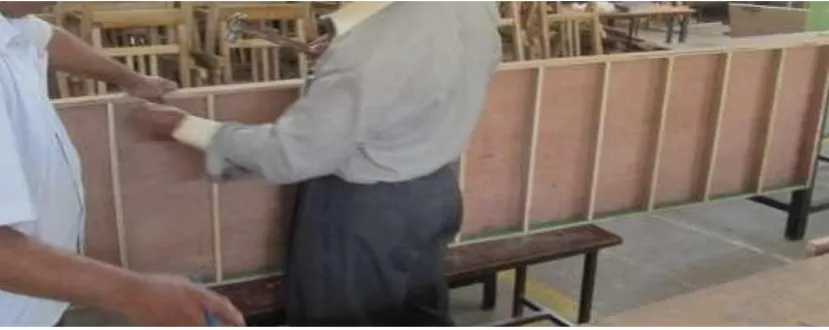
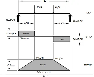
Flexural strength test: –
To find the flexural or bending strength of the specimen, this test is carried out .Here the flexural strength was carried out by using two point loading test.
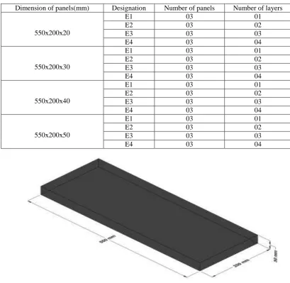
Table.2. Tested panel details
Dimension of panels(mm) Designation Number of panels Number of layers
550x200x20
E1 03 01
E2 03 02
E3 03 03
E4 03 04
550x200x30
E1 03 01
E2 03 02
E3 03 03
E4 03 04
550x200x40
E1 03 01
E2 03 02
E3 03 03
E4 03 04
550x200x50
E1 03 01
E2 03 02
E3 03 03
E4 03 04
Fig. 4. Typical specimen of 30mm thick panel
III. EXPERIMENTAL RESULTS
For 20mm thick slab panel
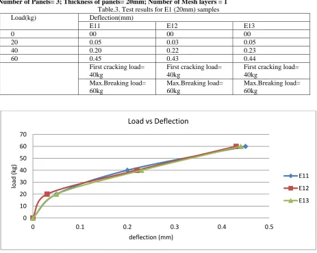
Number of Panels= 3; Thickness of panels= 20mm; Number of Mesh layers = 1 Table.3. Test results for E1 (20mm) samples
Load(kg) Deflection(mm)
E11 E12 E13
0 00 00 00
20 0.05 0.03 0.05
40 0.20 0.22 0.23
60 0.45 0.43 0.44
First cracking load= 40kg
First cracking load= 40kg
First cracking load= 40kg
Max.Breaking load= 60kg
Max.Breaking load= 60kg
Max.Breaking load= 60kg
Fig. 5. Load-Deflection curves for E1 (20mm) panels
Number of Panels= 3; Thickness of panels= 20mm; Number of Mesh layers = 2 Table.4. Test results for E2 (20mm) samples
Load(kg) Deflection(mm)
E21 E22 E23
0 00 00 00
20 0.04 0.05 0.05
40 0.10 0.12 0.12
60 0.15 0.22 0.23
80 0.29 0.31 0.37
100 0.40 0.41 0.38
First cracking load= 80kg
First cracking load= 80kg
First cracking load= 60kg
Max.Breaking load= 100kg
Max.Breaking load= 100kg
Max.Breaking load= 100kg
0 10 20 30 40 50 60 70
0 0.1 0.2 0.3 0.4 0.5
loa
d
(kg)
deflection (mm)
Load vs Deflection
E11
E12
Fig. 6. Load-Deflection curves for E2 (20mm) panels
Number of Panels= 3; Thickness of panels= 20mm; Number of Mesh layers =3
Table.5. Test results for E3 (20mm) samples
Load(kg) Deflection(mm)
E31 E32 E33
0 00 00 00
20 0.02 0.05 0.01
40 0.08 0.10 0.09
60 0.12 0.15 0.13
80 0.21 0.23 0.22
100 0.27 0.26 0.28
120 0.35 0.34 0.33
140 0.38 0.39
First cracking load= 120kg
First cracking load= 100kg
First cracking load= 100kg
Max.Breaking load= 140kg
Max.Breaking load= 140kg
Max.Breaking load= 120kg
0 20 40 60 80 100 120
0 0.05 0.1 0.15 0.2 0.25 0.3 0.35 0.4 0.45
Lo
ad
(kg)
Deflection (mm)
Load vs Deflection
E21
E22
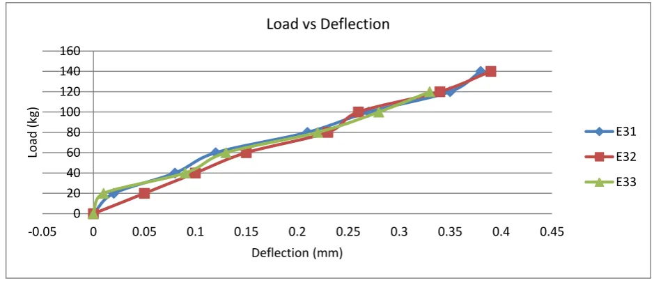
Fig. 7. Load-Deflection curves for E3 (20mm) panels
Number of Panels= 3; Thickness of panels= 20mm; Number of Mesh layers =4
Table.6. Test results for E4 (20mm) samples
Load(kg) Deflection(mm)
E41 E42 E43
0 00 00 00
20 0.03 0.05 0.04
40 0.07 0.06 0.09
60 0.09 0.10 0.13
80 0.15 0.13 0.17
100 0.21 0.20 0.19
120 0.27 0.25 0.26
140 0.29 0.30 0.32
160 0.32 0.36 0.34
First cracking load= 140kg
First cracking load= 140kg
First cracking load= 140kg
Max.Breaking load= 160kg
Max.Breaking load= 160kg
Max.Breaking load= 160kg
0 20 40 60 80 100 120 140 160
-0.05 0 0.05 0.1 0.15 0.2 0.25 0.3 0.35 0.4 0.45
Lo
ad
(kg)
Deflection (mm)
Load vs Deflection
E31
E32
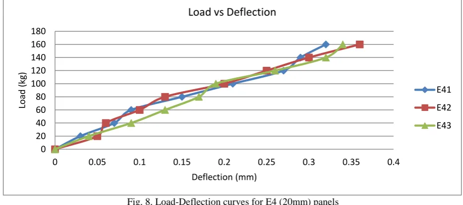
Fig. 8. Load-Deflection curves for E4 (20mm) panels
Fig. 9. Load-Deflection curves for (20mm and 30mm) panels
0 20 40 60 80 100 120 140 160 180
0 0.05 0.1 0.15 0.2 0.25 0.3 0.35 0.4
Lo
ad
(kg)
Deflection (mm)
Load vs Deflection
E41
E42
E43
0 100 200 300 400 500 600 700
0 0.1 0.2 0.3 0.4 0.5
Lo
ad
(kg)
Deflection (mm)
Load vs Deflection for 20mm and 30mm thick panels
E1(20mm)
E2(20mm)
E3(20mm)
E4(20mm)
E1(30mm)
E2(30mm)
E3(30mm)
Fig. 10. Load-Deflection curves for (40mm and 50mm) panels
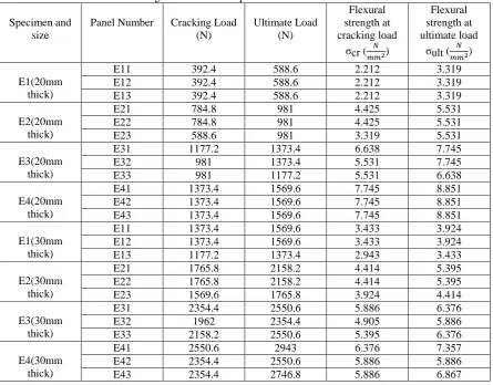
Table.7. Flexural strength of ferrocement panels of 550 mm x 200 mm dimension
Specimen and size
Panel Number Cracking Load
(N) Ultimate Load (N) Flexural strength at cracking load
σcr ( )
Flexural strength at ultimate load
σult ( )
E1(20mm thick)
E11 392.4 588.6 2.212 3.319
E12 392.4 588.6 2.212 3.319
E13 392.4 588.6 2.212 3.319
E2(20mm thick)
E21 784.8 981 4.425 5.531
E22 784.8 981 4.425 5.531
E23 588.6 981 3.319 5.531
E3(20mm thick)
E31 1177.2 1373.4 6.638 7.745
E32 981 1373.4 5.531 7.745
E33 981 1177.2 5.531 6.638
E4(20mm thick)
E41 1373.4 1569.6 7.745 8.851
E42 1373.4 1569.6 7.745 8.851
E43 1373.4 1569.6 7.745 8.851
E1(30mm thick)
E11 1373.4 1569.6 3.433 3.924
E12 1373.4 1569.6 3.433 3.924
E13 1177.2 1373.4 2.943 3.433
E2(30mm thick)
E21 1765.8 2158.2 4.414 5.395
E22 1765.8 2158.2 4.414 5.395
E23 1569.6 1765.8 3.924 4.414
E3(30mm thick)
E31 2354.4 2550.6 5.886 6.376
E32 1962 2354.4 4.905 5.886
E33 2158.2 2550.6 5.395 6.376
E4(30mm thick)
E41 2550.6 2943 6.376 7.357
E42 2354.4 2550.6 5.886 5.886
E43 2354.4 2746.8 5.886 6.867
0 100 200 300 400 500 600 700
-0.05 0 0.05 0.1 0.15 0.2 0.25 0.3 0.35 0.4 0.45
Lo
ad
(kg)
Deflection (mm)
Load vs Deflection for 40mm and 50mm thick panels
E1(40mm thick)
E11 2550.6 2746.8 3.585 3.861
E12 2354.4 2746.8 3.309 3.861
E13 2354.4 2746.8 3.309 3.861
E2(40mm thick)
E21 2550.6 2943 3.585 4.137
E22 2354.4 2746.8 3.309 3.861
E23 2746.8 3139.2 3.861 4.413
E3(40mm thick)
E31 2943 3335.4 4.137 4.688
E32 3335.4 3531.6 4.688 4.964
E33 2943 3335.4 4.137 4.688
E4(40mm thick)
E41 2943 3335.4 4.137 4.688
E42 3335.4 3531.6 4.688 4.964
E43 2943 3335.4 4.137 4.688
E1(50mm thick)
E11 3335.4 3727.8 3.002 3.355
E12 3335.4 3531.6 3.002 3.178
E13 3139.2 3531.6 2.825 3.178
E2(50mm thick)
E21 3335.4 3727.8 3.002 3.355
E22 3335.4 3531.6 3.002 3.178
E23 3139.2 3531.6 2.825 3.178
E3(50mm thick)
E31 4708.8 5101.2 4.238 4.591
E32 4512.6 4905 4.061 4.415
E33 4708.8 4905 4.238 4.415
E4(50mm thick)
E41 5493.6 5886 4.945 5.298
E42 5297.4 5689.8 4.768 5.121
E43 5493.6 5689.8 4.945 5.121
Table.8. Avg.flexural strength of ferrocement panels of 550 mmx200 mm dimension
Test group and Thickness (mm)
Compressive strength (28 Days)
Avg.flexural strength at cracking load(σcr )
Avg.flexural strength at ultimate load(σult )
E1(20mm) 42.95 2.212 3.319
E2(20mm) 42.95 4.056 5.531
E3(20mm) 42.95 5.900 7.376
E4(20mm) 42.95 7.745 8.851
E1(30mm) 42.95 3.2696 3.7603
E2(30mm) 42.95 4.2506 5.068
E3(30mm) 42.95 5.3953 6.2126
E4(30mm) 42.95 6.0493 6.7033
E1(40mm) 42.95 3.401 3.861
E2(40mm) 42.95 3.585 4.045
E3(40mm) 42.95 4.3026 4.780
E4(40mm) 42.95 4.3206 4.780
E1(50mm) 42.95 2.943 3.237
E2(50mm) 42.95 2.943 3.237
E3(50mm) 42.95 4.179 4.4736
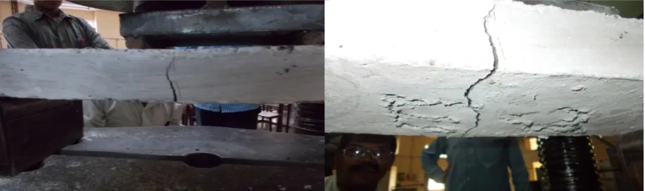
Crack pattern
Referring to figures, it can be concluded that all the samples were failed in bending because the cracks are vertical. The cracks started from the extreme fiber at the bottom and continued vertically upward until the failure reached. Most of the samples failed under the line load and a number of them failed at the mid span
.
Fig. 11.Top view of crack pattern for 20mm and 30mm thick panel
Fig. 12.TypicalTop view of crack pattern for 40mm and 50 mm thick panel
IV.CONCLUSION
Based upon the experimental test results of the ferrocement panels the following conclusions can be stated:
1. The flexural loads at first crack and ultimate loads depend on number of reinforcing mesh layers used in ferrocement. As increase in thickness and number of mesh layer, flexural strength of slab panel goes on increasing.
2. Increasing the number of layers of wire mesh from 2 to 4 layers significantly increases the ductility and capability to absorb energy of the panels. Increase in number of mesh layers improves the ductile behavior of ferrocement slabs. 3. Increasing the thickness also affected the final breaking load for slab panels. Therefore increasing the thickness of ferrocement panels from 20 mm to 50 mm significantly increases the ductility and capability to absorb energy the panels.
4. Increase in thickness of slab panels and increase in mesh layer, central deflection of slab panel goes on reducing. 5. Curvature of section just before cracking is goes on increasing with increase in the number of mesh layers.
REFERENCES
[1] S. Deepa Shri, R. Thenmozhi “AN EXPERIMENTAL INVESTIGATION ON THE FLEXURAL BEHAVIOR OF SCC FERROCEMENT SLABS INCORPORATING FIBERS”,International Journal of Engineering Science and Technology (IJEST)
[2] S. Deepa Shri, R. Thenmozhi “Flexural behavior of hybrid ferrocement slabs with microconcrete and fibers” International Journal of Emerging trends in Engineering and development, Issue 2 Vol.4 (May 2012),ISSN 2249-6149.
[3] Mohamad N. Mahmood, SuraA.Majeed “Flexural behavior of flat and folded ferrocement panels”AlRafidain Engineering, Vol 17 No.4 (Aug.2009)
[4] Chee Ban Cheah,MahyuddinRamli “Load capacity and crack development characteristics of HCWA–DSF high strength mortar ferrocement panels in flexure”construction and building material 36 (2012).Eftychios A. Pnevmatikakis, Petros Maragos “An Inpainting System For Automatic Image Structure-Texture Restoration With Text Removal”, IEEE trans. 978-1-4244-1764, 2008
[5] Chee BanCheah,MahyuddinRamli “The structural behaviour of HCWA ferrocement–reinforced concrete composite slabs” Composites: Part B 51 (2013) 68–78Aria Pezeshk and Richard L. Tutwiler, “Automatic Feature Extraction and Text Recognition from Scanned Topographic Maps”, IEEE Transactions on geosciences and remote sensing, VOL. 49, NO. 12, 2011
[6] FahrizalZulkarnain and Mohd. Zailan Suleiman“PROPERTIES OF LATEX FERROCEMENT IN FLEXURE, 2nd international conference on
built environment and developing countries (ICBEDC 2008).
[7] K. SASIEKALAA and R. MALATHY “FLEXURAL PERFORMANCE OF FERROCEMENT LAMINATES CONTAINING SILICAFUME AND FLY ASH REINFORCED WITH CHICKEN MESH” International journal of civil engineering and technology (IJCIET) ISSN 0976-6308