ANALYSIS OF MARIX CONVERTER WITH VARIOUS
INPUTS USING POWER SIMULATION
N.Sathish
1, S.Elango
2Assistant Professor, Dept. Of ECE,Sri Krishna College of Engineering And Technology,Coimbatore,Tamilnadu,India1 Assiatant Professor, Dept of EEE, Coimbatore Institute of Technology,Coimbatore,Tamilnadu,India2
ABSTRACT:Matrix converters are used to convert an AC signal to an AC signal with a different voltage and
frequency. The SPWM and SVPWM techniques are used for applying control pulses to the switches of the Matrix converter for three-phase AC to three-phase AC conversion. This greatly simplifies the complexity of the matrix converter and thereby increases the reliability of the converter. Matrix converters have applications in the adjustable speed motors found in wind turbines, generators and electric engines. A suitable pulse width modulation (PWM) technique is employed to obtain the required output voltage in the line side of the inverter. The different methods of PWM generation such as sine PWM (SPWM), Space Vector PWM (SVPWM) are implemented in this project. In sine-triangle PWM, three phase reference modulating signals are compared against a common triangular carrier to generate the PWM signals for the three phases. In SVPWM methods, a revolving reference voltage vector is provided as voltage reference instead of three phase modulating waves. In this paper, the model for SPWM and SVPWM technique is made and simulated using PSIM 9.0.3.400 software and its performance is compared with matrix converter. The control pulses for the matrix converter are developed by using C programming.
KEYWORDS:SPWM.SVPWM,MatrixConverter,PWM
I. INTRODUCTION
The progress in the development of power device (silicon) technology and large power integrated circuits encouraged the interest of research to explore an AC-AC matrix converter as an elegant silicon-intensive and efficient way to convert AC input supply directly into AC output supply. However, the power converter is still not utilized in industry because of the difficulties involved in the practical implementation related to bi-directional switch realization, zero current commutation problems, the complexity of the PWM control method, the synchronization and the protection problems. It is hoped that the AC-AC matrix converter topology will replace the work of standard AC-DC-AC converters . In this project matrix converter is made to operate in the following modulation techniques namely SPWM and SVPWM. Compared to SPWM technique, SVPWM are more suitable for digital implementation. Also the maximum voltage transfer ratio can be increased up to 87% [2]. The comparative method reveals the superiority of the SVPWM over PWM technique in terms of THD. The three phase ac line voltage is applied to matrix converter after appropriate filtering. The matrix converter converts the fixed voltage to voltage with variable amplitude and frequency. The output can be supplied to any load that requires variable voltage with variable frequencies such as to drive an induction motor and the permanent magnet synchronous motor. This topology can be used in the fields of industrial AC motor drives, in a marine application, in a military application especially for military vehicles, in an aerospace application.The control pulses for the converter are developed in C programming. The proposed modulation techniques for matrix converter are Sinusoidal Pulse Width Modulation (SPWM) and Space Vector Pulse Width Modulation (SVPWM).
II.MATRIX CONVERTER
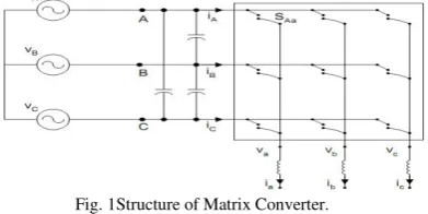
frequency AC drive applications. The main advantage of a matrix converter is to obtained variable frequency output from fixed frequency input supply.The matrix converter consists of 9 bi-directional switches that allow any output phase to be connected to any input phase. With nine bi-directional switches the matrix converter can theoretically assume 512 different switching states combinations. But not all of them can be usefully employed [1]. Regardless to the control method used, the choice of the matrix converter switching states combinations to be used must comply with two basic rules.The input terminals of the converter are connected to a three phase voltage-fed system, usually the grid, while the output terminal are connected to a three phase current- fed system, like an induction motor might be. Taking into account that the converter is supplied by a voltage source and usually feeds an inductive load, the input phases should never be short-circuited and the output currents should not be interrupted. From a practical point of view these rules imply that one and only one bi -directional switch per output phase must be switched on at any instant.
Fig. 1Structure of Matrix Converter.
One of the key benefits of the Matrix Converter technology is the possibility of greater power density due to the absence of a DC link. This is translated into a realistic advantage if the filter size is also optimized, by having a sufficiently high switching frequency of semiconductor devices. This means, though, a compromise between filter size and semiconductor losses must be found. Factors such as the absence of electrolytic capacitors, the advantage for increasing power density, reducing size, reducing weight and obtaining good input power quality are fundamental to power supply applications.
A. Static Frequency Changer (AC/AC Converter)
A static frequency changer is a converter which can convert ac power at a given frequency to ac power at a different frequency. In this conversion, voltage magnitude and phase angle can be controlled as well. The block diagram of a three-phase to three-phase static frequency changer is shown below.
Fig. 2Block diagram of frequency changer.
The input power supply with fixed frequency is applied to the frequency changerblock. The frequency changer changes the frequency of the input power supply depending on the required output frequency. The variable frequency output voltage is obtained from the frequency changer [8]-[10]. Therefore, electrical energy can be transferred between the input and output of the converter without a dc-link. A single-stage static frequency changer can be realized by thyristor. In that case, it is called a naturally-commutated cycloconverter, featuring restricted frequency conversion. It is also possible to realize a single-stage static frequency changer by controllable switches. In this case, it is called a forced- commutated cycloconverter or a Matrix Converter (MC).
The Matrix Converter requires a bi-directional switch capable of blocking voltage and conducting current in both directions. Unfortunately there are no such devices currently available, so discrete devices need to be used to construct suitable switch cells. There are three types of Bi-directional switches are available they are
1) Diode bridge bi-directional switch cell arrangement. 2) Common emitter back-to-back.
3) Common collector back-to-back.
Fig. 3 Bi-directional switches
The diode bridge bi-directional switch cell arrangement consists of an IGBT at the center of a single-phase diode bridge arrangement is shown in above fig. The common emitter and common collector bi-directional switch cell arrangement consists of two diodes and two IGBTs connected in anti-parallel as shown in above fig. The disadvantage of the
arrangement is the need of two isolated power supplies for the two gate drivers of the IGBT’s. The diodes are included
to provide the reverse blocking capability .In this project diode bridge bi-directional switch cell arrangement because the main advantage is that both current directions are carried by the same switching device, therefore only one gate driver is required per switch cell. The cost of the hardware implementation is also reduced because of only 9 IGBT is used.
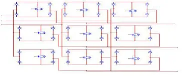
IV. IMPLEMENTATION OF MATRIX CONVERTER
The implementation of matrix converter using diode bridge bi-directional switch cell arrangement is shown in fig. The individual pulses for IGBT is obtained using two different modulation techniques. The three phase input supply is given to the each leg of the matrix converter and the three phase output is obtained from the each leg of matrix converter. At every instant of time only three switches of a matrix converter is in ON state remaining switches must be in OFF state [9]. The two modulation techniques are Sinusoidal Pulse Width Modulation (SPWM) and Space Vector Pulse Width Modulation (SVPWM) techniques.
Fig. 4 Implementing Matrix Converter Circuit in PSIM Environment
V.MATRIX CONVERTER USING SINUSOIDAL PULSE WIDTH MODULATION
Sinusoidal PWM refers to the generation of PWM output sine wave as the modulating signal. The on and off instants of a PWM signal in this case can be determined by comparing a reference sine wave (the modulating wave)with a high frequency triangular wave (the carrier wave).Sinusoidal PWM technique is commonly used in industrial applications and is abbreviated here as SPWM. The frequency of the modulating wave determines the frequency of the output voltage.
A. Pulse Generation Logic For Matrix Converter
used for generating pulses for IGBT’s in the matrix converter after performing certain logic. The generation of SPWM is shown in figure.
Fig.5 SPWM generation
In the SPWM technique different phase shifted sinusoidal waveform is compared with triangular waveform. The three phase shift of sinusoidal waveform is 0,120&240 degrees. This will create six different output pulses, that pulses are applied to the
control logic function.The pulses for the IGBT’s in the matrix converter are generated with certain logic as shown in figure.
B. Simulation Of Matrix Converter Using SPWM
The matrix converter using SPWM is designed with the help of PSIM software. Individual sub-blocks are created for SPWM generation, gate logic and matrix converter. The simulated circuit diagram of MC using SPWM is shown in below figure.
Fig.6 Simulation circuit for Matrix Converter using SPWM
VI. MATRIX CONVERTER USING SPACE VECTOR PULSE WIDTH MODULATION TECHNIQUE
Space Vector Modulation (SVM) was originally developed as vector approach to Pulse Width Modulation (PWM). It is a more sophisticated technique for generating sine wave that provides a higher voltage to the motor with lower total harmonic distortion. The main aim of any modulation technique is to obtain variable output having a maximum fundamental component with minimum harmonics. Space Vector PWM (SVPWM) method is an advanced computation intensive PWM method and possibly the best techniques for variable frequency drive application. SVPWM is a different approach from PWM modulation,
based on space vector representation of the voltages in the α-β plane. The α-β components are found by Clark’s transformation. Space Vector PWM (SVPWM) refers to a special switching sequence of the upper three power transistors of a three-phase power inverter. It has been shown to generate less harmonic distortion in the output voltages and/or currents applied to the phases of an AC motor and to provide more efficient use of dc input voltage. Because of its superior performance characteristics, it has been finding widespread application in recent years.
A. Simulation Of Mc Using SVPWM
SVPWM Generation,
Basic switching, vectors and sectors. Modeling of space vector
Step # 1 determination of Vd, Vq, Vref and angle (a) Step # 2 determination of time duration T1, T2, T0
Step # 3 determination of switching time of each transistor (S1 to S6) Step 1:
Vd, Vq, Vref, Line Voltage = 500 Van = Vbn = Vcn = 230
Vq = Vbncos (θ) − Vcncos (θ)
√
The three phase coordinating input supply is converted to two phase rotating system by using the equation. The sector can be obtained by calculating the angle from the values of Vd and Vq.
Step 2:
Determination of time duration:
,
is fundamental frequency
The pulse duration for generation of pulses is implemented in PSIM as shown in figure. The calculated angle is used for calculating the time duration of each pulse.
B. Time Duration Calculation
The monostable multivibrator is used for obtaining duration of pulses. The constant values are given to the output of the multivibrator. From that results six various SVPWM output is obtained for generating pulses for IGBT’s in matrix converter.
C. Implementation Of Mc Using Svpwm
The matrix converter is designed using SVPWM as shown in figure.The individual circuits are formed into sub-blocks.Various loads are connected to the output of the matrix converter.
Fig.7 Matrix Converter using SVPWM simulation circuit
VII.SIMULATION RESULTS
The simulation of matrix converter using SPWM and SVPWM is designed and simulated with various R load and their performance is studied. The variable frequency output is obtained in matrix converter using both SPWM and SVPWM.
A. Simulation Results For Matrix Converter Using SPWM
The simulation result for the MC using SPWM with modulation index=0.25
Fig.8 Modulation Index=0.25
D. Simulation Results For Matrix Converter Using SVPWM
The simulated results are obtained with various loads and various modulation indexes. The results are shown below Simulation Results for Matrix Converter with R Load
The simulation result for the MC using SVPWM with modulation index=0.25 is shown in figure.
Fig.9 Modulation Index=0.25
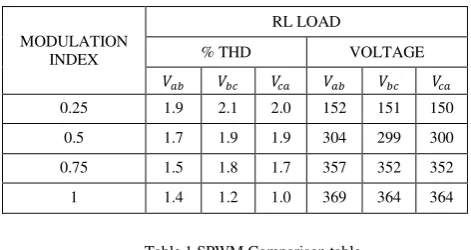
E. Measurement ofPercentage THD andOutput Voltage inMC Using SPWM WithRL Load.
MODULATION INDEX
RL LOAD
% THD VOLTAGE
0.25 1.9 2.1 2.0 152 151 150 0.5 1.7 1.9 1.9 304 299 300 0.75 1.5 1.8 1.7 357 352 352 1 1.4 1.2 1.0 369 364 364
Table 1 SPWM Comparison table
F. Measurement of Percentage THD and Output Voltage in MC Using SVPWM with RL Load
MODULATION INDEX
RL LOAD
% THD VOLTAGE
0.25 0.5 0.6 0.5 289 285 287 0.5 0.5 0.6 0.5 289 285 287 0.75 0.6 0.5 0.5 297 297 298 1 0.8 0.9 0.6 312 309 310
Table 2 SVPWM Comparison table
0 0.05 0.1 0.15 0.2 0.25 0.3
T i m e (s) 0
-100 -200 -300 100 200 300
S5.VP1 S5.VP5 S5.VP6
0 0.05 0.1 0.15 0.2 0.25 0.3
T i me (s) 0
-200 -400 -600 200 400 600
G. Output Voltage with Variable Frequency in MC Using SPWM
The input three phase supply frequency is 50Hz and the obtained output three phase supply frequency is 40Hz. The frequency is varied by changing the frequency of sinusoidal input in the SPWM generation. The variable frequency output is shown in figure.
Fig.10 Output Of Variable Frequency In Matrix Converter Using SPWM.
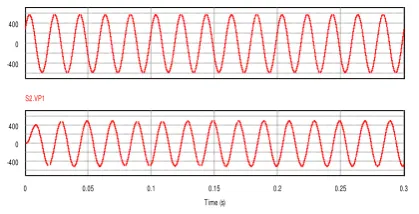
H. Output Voltage With Variable Frequency In Mc Using Svpwm
The input three phase supply frequency is 50Hz and the obtained output three phase supply frequency is 40Hz. The frequency is varied by changing the frequency of sinusoidal input in the SVPWM generation. The variable frequency output is shown in figure.
Fig.11 Output Of Variable Frequency In Matrix Converter Using SVPWM.
VIII. CONCLUSION
This project demonstrated the analysis, design, and development of the three-phase-to-three-phase AC-AC matrix converter with SPWM and SVPWM techniques in PSIM software. A background study of the various topologies of the matrix converter and the associated controlling algorithms was investigated. Theoretical background of the simulation results of three-phase-to-three-phase AC-AC matrix converter with SPWM and SVPWM topologies were presented. The results for percentage THD, output voltage and output variable frequency of both MC using SPWM and MC using SVPWM is presented.From the simulation results it is concluded that matrix converter using SVPWM gives less THD percentage in output waveform and high output voltage as compared to the matrix converter using SPWM. The results of the simulation test proved that the converter successfully complied with its specifications. Thus the three-phase matrix converter using SVPWM can be used as a replacement of the conventional rectifier-inverter based converter. The advantages of the matrix converter in short are:
Inherent four -quadrant operation
Absence of bulky DC-link electrolyte capacitors
Pure input power characteristics with unity power factor
Small sized all-silicon, and cost effective converter.
0
-400 400
VP7
0 0.05 0.1 0.15 0.2 0.25 0.3
Time (s) 0
-200 200
S5.VP1
0 -400 400
VP7
0 0.05 0.1 0.15 0.2 0.25 0.3 Time (s)
0 -400 400
REFERENCES
[1] A. Alesina and M. G. B. Venturini, "Analysis and design of optimum amplitude nine-switch direct AC–AC converters,” IEEE Trans. Power Electron., vol. 4, Jan. 1989, pp. 101–112.
[2] L. Huber and D. Borojevic, "Space vector modulated three phase to three phase matrix Converter with input power factor correction,” IEEE Trans. Ind. Application, vol. 31, Nov./Dec. 1995, pp. 1234–1246,
[3] Xiyou Chen and MehrdadKazerani, “Space Vector Modulation Control of an AC–DC–AC Converter With a Front-End Diode Rectifier and Reduced DC-link Capacitor”, IEEE Transactions On Power Electronics, Vol. 21, No. 5, 2006,pp.1470-1476,
[4] HuseyinAltun,SedatSunter,“Simulation And Modeling Of Vector Controlled 3-Phase Matrix Converter Induction Motor Drive”, ELECO’01, Bursa, Nov. 7-11, 2001, pp.98-102.
[5] EbubekirErdem, Yetkin Tatar, and SedatSünter, “Modeling and Simulation of Matrix Converter Using Space Vector Control Algorithm”, EUROCON 2005, November 22-24, 2005, pp. 25-32.
[6] J. Ashwin Kumar Sahoo,S. Meenakshe, S Dash, and T. Thyagarajan, “Analysis and simulation of Matrix ConverterUsing PSIM”, The 7th International
Conference on Power Electronics, oct-2007, pp. 414-419,
[7] P. Nielsen, “The matrix converter for an induction motor drive”, Industrial Ph.D. project EF493, ISBN 87-89179-14-5, 296 pages, Aalborg University, Denmark,1996.
[8] M. Kazerani, Dynamic Matrix Converter Theory Development and Application, Ph.D. thesis, Department of Electrical Eng., McGill University, Canada, 1995.
[9] B.T. Ooi and M. Kazerani, "Application of dyadic matrix converter theory in conceptual design of dual field vector and displacement factor controls", in Proc. IEEE Industry Applications Society Annual Meeting, Vol. 2, Oct. 1994, pp. 903-910.
[10] H. Nikkhajoei, A. Tabesh, and R. Iravani, "Dynamic model of a matrix converter for controller design and system studies", IEEE Trans. on Power Delivery, Vol. 21, Issue 2, Apr. 2006, pp.744 – 754.
[11] C.L. Neft and C.D. Schauder, “Theory and Design of a 30-Hp Matrix Converter”, in Conference Records of IEEE/IAS Annual Meeting, 1988, pp. 934-939.
[12] N. Burany, “Safe Control of Four-Quadrant Switches,” in Conference Records of IEEE/IAS Annual Meeting, 1989, pp. 1190-1194.