Transactions of the 17th International Conference on Structural Mechanics in Reactor Technology (SMiRT 17)
Prague, Czech Republic, August 17 –22, 2003
Paper # J07-1
Interactions Between Cask Components and Content of Packaging for the
Transport of Radioactive Material During Drop Tests
T. Quercetti, V. Ballheimer, P. Zeisler, K. Müller
Federal Institute of Material Research and - Testing, D-12200 Berlin, Germany
ABSTRACT
This paper describes the analytical, numerical and experimental investigations on the phenomenon of interactions between cask components and content of packages for the transport of radioactive material during drop tests required according to the IAEA Regulations for the Safe Transport of Radioactive Material.
Radial and axial gaps between cask components and content are usually necessary for thermal reasons but larger gaps can exist because of the geometrical dimensions of the specified content. Consequently interactions between content and cask components (lid system, cask body, etc.) are possible and can not be excluded during drop tests. Interactions in this context are relative movements between cask and content which are mainly due to elastic spring effects after releasing the cask for the free drop. These relative movements can cause interior collisions between content and cask during the main impact of the package onto the unyielding target.
Drop tests with various types of Type A and Type B packages fully instrumented with strain gauges and accelerometers showed that these interactions respectively interior collisions can be considerable relating to high forces acting on cask lids, lid bolts and the content. Of course the real quantitative consequences of the interactions depend upon different conditions, among others the drop orientation, the design characteristics of the impact limiters, the dimensions of the gaps, the material characteristics of the contents, etc. .
In order to investigate more precisely the phenomenon of interactions BAM carried out finite element calculations for the named casks using the ABAQUS/ Standard and ABAQUS/ Explicit computer code comparing them with results obtained from experiments. Additionally, tests with a simplified model instrumented with accelerometers were carried out accompanied by finite element calculations and analytical calculations using MATHEMATICA. The investigations on the mentioned phenomena of interaction show that they should be considered in approval design tests and/ or calculations.
KEY WORDS:
interaction, drop test, internal collision, content, cask components, interaction, package, finite element, gap, relative movement, releaseINTRODUCTION
Experiences basing on tests with different Type B casks confirm that a “two-mass" effect with stress peaks in cask components due to interactions between the cask and its content really exist. These interactions can be caused by a delayed strike of the content onto surrounding cask components. Particularly, vertical drops onto the lid side of casks can induce stress peaks in the cask lid and in the lid bolts. In principle, interactions between cask components and the content of the cask can not be excluded if the content is not arrested. Large gaps between content and cask components, e.g.. the cask lid, enhance the risk of dangerous consequences of interactions. The risk of a component failure would especially exist if interactions occur during rebound of the cask.
Nine meter drop tests performed with Type B packages equipped with accelerometers at cask components and content have shown signals in some cases which prove a distinct interaction between the cask and its content. For example, this effect appeared at a 9 m drop of a MOSAIK cask flat onto the lid side shock absorber. That cask was loaded with a drum filled with concrete-conditioned waste. The drum was not arrested and the axial gap between the drum and the cask bottom (at the drop position tested) was rather large. The test results were presented at PATRAM 2002 [1] and will be summarised in this paper.
Interactions between the content and cask components were also confirmed by tests of BAM with other Type B casks, e.g., with the ESBB cask that is used for transport of single fuel assemblies. This was illustrated by deformations of the bottom part of the fuel assembly dummy after a vertical 9 m drop that can be only explained by delayed strike of the fuel assembly onto the cask bottom. The delayed interaction between fuel assembly and cask bottom was reflected also by the signals of accelerometers attached to the content and the cask as well.
use of analytical methods in order to prove also the effects measured at the MOSAIK and ESBB cask and the test model as well by numerical analyses.
DROP TEST WITH THE ESBB CASK
The ESBB cask was developed by NCS (Nuclear Cargo + Service GmbH, Hanau) for transports of single spent fuel assemblies of the SNR 300 fast breeder reactor. The ESBB is licensed as Type B(U) package [3]. The drop test discussed in this paper was one of several drop tests performed by BAM within the approval procedure of the cask according to the IAEA Regulations.
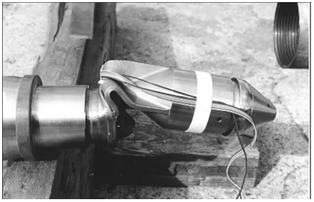
The ESBB cask (Figure 1) consists of a stainless steel tube closed by a welded bottom and a welded main plug on the top side. The top side is welded after loading. Bottom and main plug are protected by shock absorbers. Important dimensions of the cask are: outer/inner diameter 159 mm/ 139 mm, total/ usable length 4538 mm/ 3708 mm. The weights of content and of the loaded cask are 140 kg and 340 kg, respectively. The SNR 300 fuel assembly has a length of 3680 mm and consists of 166 fuel pins with 6 mm diameter. The fuel pins are enclosed in a hexagonal cladding box with a maximum diameter of 131 mm.
The ESBB cask was subjected to several drop tests with different orientations. The following discussion of test results concerns only the vertical 9 m drop onto the bottom side shock absorber because of its special importance with regard to the "inner collision problem”. The cask was loaded with a fuel assembly dummy. The fuel pins were substituted by a single steel rod. The gap between the dummy and the main plug of the cask amounted in the position before release to 27 mm.
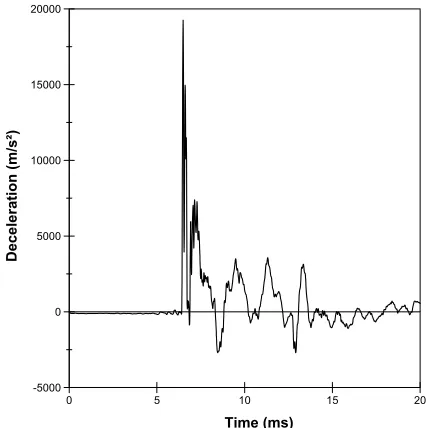
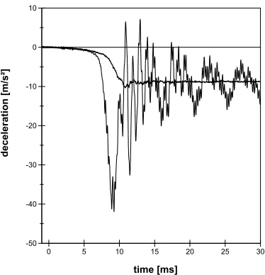
On the top side of the cask body and in the foot of the fuel assembly piezoelectric accelerometers with a built-in mechanical filter system and a 5000 g full-scale output range were mounted. The measured maximum decelerations were 350 g at the cask body and 1600 g at the fuel assembly (Figures 2 and 3). The maximum signal of the content accelerometer appeared 6.5 ms after the impact of the cask at time t = 0 onto the unyielding target. This indicates clearly the delayed interior impact of the fuel assembly onto the bottom plate of the cask body. That nearly undamped strike of the fuel assembly with its high differential velocity ∆v to the cask (Figure 4) is the reason for
the strong deformation of the lower part of the fuel assembly dummy (Figure 5).
0 5 10 15 20
Time (ms) -5000
0 5000 10000 15000 20000
Deceleration (m/s²)
0 5 10 15 20
Time (ms) -5000
0 5000 10000 15000 20000
Deceleration (m/s²)
Figure 1. ESBB cask for the 9 m vertical drop test onto the bottom side shock absorber
Figure 3. ESBB; Measured deceleration- time signal of the content.
main plug (welded)
3860 m
m
27 mm
head of the fuel assembly
cask body
fuel assembly
bottom (welded)
Figure 6. Finite- Element Model of the ESBB cask and fuel assembly (shock absorber not part of the model).
The effectiveness of the shock absorber was insignificant at that time because of its deformation (74 % of the final value) in the preceding phase of the impact.
Finite- Element Calculation
Primary objective of the FE- analyses was the explanation of the kinetic behaviour of the cask and its content after release of the test object and during the phase of its free fall. The FE model consists of 42,000 hexagonal elements with 58,920 knots (Figure 6). ABAQUS/Standard was used to calculate the static deformation of content and of the cask components before the drop due to their self-weights. The release and the free drop phases were analysed with ABAQUS/Explicit importing the deformed mesh from ABAQUS/Standard to ABAQUS/Explicit as initial condition. Linear-elastic material characteristics are taken into account in these calculations.
The results of the numerical analyses reproduce the test results in a satisfying manner: The distance between content and cask bottom plate at the time of cask impact amounts to 20 mm (Fig.8). Nearly the same value (19 mm) was derived by integration of the measured decelerations. Additionally, Fig. 7 show the time histories of the displacements which were calculated with ABAQUS/ Explicit indicating likewise the delayed content-cask bottom interaction.
0 5 10 15 20 25 30 35 40
Time (ms) -14
-12 -10 -8 -6 -4 -2 0 2
Velocity (m/s²)
Figure 4. ESBB; Velocity-time histories of the cask ( ) and the fuel assembly (∆).
Figure 5. ESBB; Deformed foot of fuel assembly after the 9 m vertical drop test onto the bottom shock absorber
1.3 1.31 1.32 1.33 1.34 1.35 1.36 time [ms]
-9.1 -9 -8.9 -8.8 -8.7 -8.6 -8.5 -8.4 -8.3 -8.2
di
s
pl
a
c
e
m
e
nt
[
m] ESBB - container
fuel assembly
∆s = 20 mm
Figure 8. Calculated position of the fuel assembly relatively to the cask bottom at time when the container hits the target Figure 7. Calculated displacement histories of the cask
and the fuel assembly during the last 0.06 sec. before the cask hits the target
Figure 9. MOSAIK cask loaded with a moveable drum.
DROP TEST WITH THE MOSAIK CASK
The test reported here was performed by GNS (Gesellschaft für Nuklear-Service mbH, Essen) witnessed by BAM. It is one of the tests required by BAM in order to estimate the mechanical consequences which possibly could arise due to envisaged new modifications of contents to be transported with the MOSAIK cask.
The MOSAIK cask has a height of 1500 mm, an outer diameter of 1060 mm and a wall thickness of 160 mm. It is manufactured from ductile cast iron (DCI). The cask lid (also DCI) has a thickness in its central part of 180 mm and its flange is 100 mm thick. The cask lid is screwed with the cask body by 24 cylindrical head screws M 36. The wooden layers of the lid side shock absorber have an effective thickness of 200 mm. The MOSAIK cask exists in several modifications. The test model had no inner lead shielding, and the lid bolt material was a ferrittic steel with a 0.2 % yield stress (Rp0.2) of 640 MPa. The weights of the
package and the content amounted 9780 and 1250 kg, respectively.
With regard to the interactions between the cask components and the content the 9 m drop onto the lid side shock absorber was the most interesting drop position. Fig. 9 shows the package configuration before dropping. The gap between drum and cask bottom amounted to 255 mm. In order to avoid a sideward movement of the drum it was axially guided by two guiding rails.
As the most important test result Figure 10 shows the velocities of cask lid, cask bottom and the content. It illustrates clearly the delayed strike of the content onto the cask lid: Until 10 ms after the cask impact the velocity of the content did not change. This is also reflected by Figure 12 which shows that the distinct deflection oscillations of the cask lid centre begin exactly at the moment of the sharp decrease of the velocity of the content.
.
Figure 10: MOSAIK; Velocity histories of the components (test results)
Figure 11: MOSAIK; Velocity histories of the components (results of the finite-element calculation)
0 5 10 15 20 25
Time (ms)
-1 -0.8 -0.6 -0.4 -0.2 0 0.2 0.4 0.6 0.8 1
D
isp
lac
em
en
t (
m
m
)
test
FE calculation
Finite Element Calculation
Primary objective of the finite element calculation was the reproduction of the measured effects caused by the interaction between content and cask lid. The gap of 17 mm between the content and the cask lid at the time of cask impact onto the unyielding target that would cause the measured time delay of the interaction (10 ms) was considered also in the FE calculations. The shock absorber was modelled as a homogeneous material that considers the compound behaviour of the sheet structure as well as the energy absorbing characteristics of the wood enclosed therein [4]. The ABAQUS ‘crushable foam’ model was applied to simulate the inelastic behaviour of the shock absorber. Except of the bolts which consists of spring elements all components are modelled by
use of isoparametric three-dimensional cubic continuum elements with linear interpolation and reduced integration.
The comparison between the measured and calculated curves in Figures 10, 11 and 12 show a satisfying agreement. The lower frequency of the measured oscillations of velocities and deflections are explainable by the rather low frequency that was used for filtering of the measured signals. But the analyses showed also that the reproduction of the measured curves requires an exact modelling of all important details which can influence the results of calculation.
TESTS WITH A "TWO- MASS" MODEL
The test model was designed in order to carry out basic studies to explain the phenomena of interactions and their effects (Figure 13). Especially, the relative motion between content and cask and the real cause for it should be studied. The content were represented in the model by a rigid hollow cylinder (in the diagrams named as ‘mass’) with a weight of 138 kg. The cask is simulated by a support consisting of a guiding tube for the hollow cylinder and two plates at the ends of the tube. The bottom plate was equipped with a wooden shock absorber. In order to show the expected effects clearly the weight of the hollow cylinder was a multiple of the weight of the support structure (18 kg).
0 5 10 15 20 25
time [ms]
-14 -12 -10 -8 -6 -4 -2 0 2
velocity [m/s]
drum cask lid cask bottom
0 5 10 15 20 25
time [ms]
-14 -12 -10 -8 -6 -4 -2 0 2
velocity [m/s]
drum cask lid cask bottom
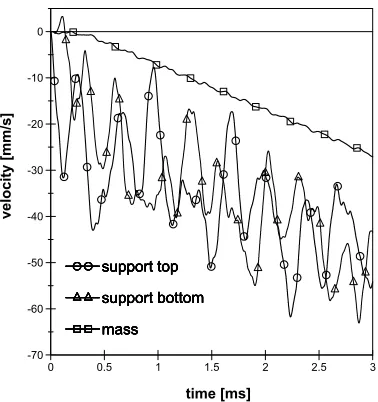
The test model was equipped with accelerometers at the top and bottom plate of the support as well as on the hollow cylinder. Accelerometers with a specified measuring range were used to record the low accelerations at the moment of release of the test model and during the free fall. Figure 14 shows the signals measured on the top plate of the support and on the hollow cylinder over a time period of 30 ms after release (t = 0). After release of the model the hollow cylinder stabilised within a few milliseconds to a constant acceleration of 9.81 m/s2 (1
g), i.e., the acceleration due to gravity. Whereas, the support top and bottom was additionally accelerated to a peak value four times higher than the gravitational acceleration. This additional acceleration caused a small velocity difference
∆
v
between the hollow cylinder and the support resulting finally in the gap∆
s
between hollow cylinder and support at time of impact.Additionally, the effects after the release of the test object were investigated using the ABAQUS code as well as a simplified mass-spring model.
The FE- model of the test object in the final phase of the drop is shown in Figure 15. All components of the FE-model were simulated by three-dimensional cubic continuum elements with linear interpolation and reduced integration. A linear-elastic material law was used. At first, the static deformation of the system before release of the test model was calculated. It was used as initial condition for the calculation of the motion after the release. The displacement histories of support and cylinder (Figures 16 and 17) show clearly the delayed motion of both components. Figures 17 and 18 demonstrate the histories of the displacements and velocities during the first 3 ms after release. The different initial displacement values in hanging position of the test object at time t = 0 (Figure 17) are due to forces of gravity. The gravity force of the cylinder causes an elastic elongation of the support and an elastic bending of the bottom plate. For this reason the cylinder has the highest static displacement. After release, the cylinder keeps for a split millisecond in neutral state while the support accelerates due to the reverse elastic spring effect of the before in hanging
Figure 13. Test object.
0 5 10 15 20 25 30
time [ms]
-50 -40 -30 -20 -10 0 10
deceleration [m/s²]
Figure 14. Deceleration history of mass and support top after release.
Figure 15. Finite-element model of the test object.
g x3
x2 x1
c1
c3
m1
m2
m3
Figure 19. Simplified mass-spring model of the test object
Figure 16. Displacement histories of support and cylinder over 100 ms free fall
0 0.5 1 1.5 2 2.5 3
time [ms]
-0.1 -0.08 -0.06 -0.04 -0.02 0
displacement [mm]
mass support bottom support top
mass support bottom support top
mass support bottom support top
mass support bottom support top
Figure 17.Displacement histories of support an cylinder over a time period of 3 ms after release
0 10 20 30 40 50 60 70 80 90 100
time [ms] -50
-40 -30 -20 -10 0
dis pla ce me nt [m m]
position elongated support. This causes a small velocity difference
v
∆
between the hollow cylinder and the support resulting finally in the gap∆
s
.The mass- spring model is shown in Figure 19. The masses m1 and m2 reproduce the masses of the top and bottom plates,
respectively, each heightened by the half mass of the guiding tube. They are linked together by an undamped massless spring with the spring constant c1 which models the elasticity of the tube. The mass
m3 overlies free on the spring c3 which is connected to the mass m2.
Thereby, the elastic behaviour of the bottom plate is simulated. The motion of this mass-spring model after the release can be described by the system of differential equations (1) - (3) with consideration of the initial conditions (4) for the static deformations of the springs in the hanging position before release:
0 ) ( )
( 1 1 2 1
1 x −g −c x −x =
m && (1)
0
0
,
0
0
),
(
)
(
)
(
3 2 3 2 3 2 3 1 2 1 2 2=
>
−
≤
−
−
+
−
+
−
x
x
if
x
x
if
x
x
c
x
x
c
g
x
m
&&
(2)0 0 , 0 0 ), ( ) ( 3 2 3 2 3 2 3 3 3 = > − ≤ − − − − x x if x x if x x c g x
m && (3)
For
t
=
0
;x
1(
0
)
=
0
,x
2(
0
)
=
x
2,st,x
3(
0
)
=
x
2,st+
x
3,st0
)
0
(
)
0
(
)
0
(
2 31
=
x
=
x
=
x
&
&
&
(4)For the numerical solution of the kinetic equations the program “Mathematica” [5] was used. The results of calculations for the first 3 ms after release are compared with the FE results in figure 20. Just before the test object contacted the unyielding target, both the FE-model and the mass-spring model calculated a gap between the bottom plate and the hollow cylinder of about 13 mm. However, the gap determined by the integration of the accelerations measured during the test (figure 14) amounted to about 25 mm. Some effects which were probably not reproduced by the calculation could be the reason for this discrepancy (e.g. the sliding of the holding rope on the hook). Nevertheless, the qualitatively satisfying agreement of the results of both calculation models confirm that the deformation energy stored in the components of the test model before its release was the main cause for the relative motion between the hollow cylinder and the support after release.
CONCLUSION
Tests performed by BAM (and also by applicants) show unambiguously that the "two-mass" problem exists. In principle, interactions between movable, i.e., non arrested contents are possible
by delayed interactions between content and cask components. Primary reason is the momentum which results from the loss of their deformation after release of the package from the notching attachment. The resultant effective force is influenced by the real conditions which can reduce or eliminate the effect of the momentum (dimension of gaps,
non-0 0.5 1 1.5 2 2.5 3
time [ms] -70 -60 -50 -40 -30 -20 -10 0 velocity [mm/s] mass support bottom support top mass support bottom support top mass support bottom support top mass support bottom support top mass support bottom support top
Figure 18. Velocity histories of support and cylinder over a time period of 3 ms after release
Figure 20. Comparison between finite-element and analytical solution. Displacement histories of support and cylinder over a time period of 3 ms after release
0 0.5 1 1.5 2 2.5 3
time [ms] -0.1 -0.08 -0.06 -0.04 -0.02 0
displacement [mm]
ideal position of content, friction, adhesion effects, etc.). This is obviously the reason that the two-mass effect is more or less noticeable in real tests.
The effect of the momentum which results in a different start velocity of content and cask after the release of the package can also demonstrated by numerical analyses. Idealised conditions which are usually taken into consideration in doing so (ideal position of content, no friction between content and cask walls, etc.) lead to the conclusion that it is rather difficult to quantify the effects exactly by numerical analyses. Therefore, on one hand the idealised numerical analyses seems to be often a conservative approach to the reality but it includes on the other hand not those conditions which really appeared in performed tests.
Because of their disadvantageous effects one should minimise the dimension of gaps between the content and the cask components. In principle, it is possible by an appropriate cask design. This includes the preparation of measures which are probably necessary for specified content and which allow to reduce a gap dimension after loading of a cask.
REFERENCES
[1] P. Zeisler, B. Gogolin, V. Ballheimer, J. Pöppinghaus, Strain of Lid Bolts of Type B Packages during 9 m Drop Tests – Results of Real Tests and Problems of Analytical Prediction. The13th International Conference on Packaging and Transportation of Radioactive Materials, September 3-8, 2001; Chicago, Illinois, USA; Revised Proceedings, paper 33238 (CD),
[2] ABAQUS/ Standard andABAQUS/ Explicit User’Manual. Hibbit, Karlsson & Sorensen, Inc., HKS, 1080 Main Street Pawtucket, RI 02860-4847, Version 5.8 Edition 1998
[3] F. Hilbert, The ESBB Package for the Transport and Interim Storage of MOX Fuel Assemblies and Pins.
The13th International Conference on Packaging and Transportation of Radioactive Materials, September 3-8, 2001; Chicago, Illinois, USA; Revised Proceedings, paper 33393 (CD)
[4] V. Ballheimer, A. Probst, B. Droste, Numerical Assessment of Spent Fuel Casks Impacting on Real Targets, RAMTRANS, Vol. 11, Nos 1-2, pp. 45-51 (2000)