ABSTRACT
METZGER, BRIAN. Glycerol Combustion. (Under the direction of William L. Roberts).
As worldwide production of biodiesel fuel increases, a growing concern is the abundance of waste glycerol. The price of crude glycerol has fallen drastically and many large biodiesel producers are currently paying to landfill this large waste stream. In the search to find a value-added alternative, glycerol combustion may be one of the simplest solutions. Heat recovered from glycerol oxidation could easily be used to reduce heating costs inherent to large-scale biodiesel production. It has been stated “Combustion of glycerol would be an elegant solution, if it worked” (journeytoforever.com). Clean combustion of glycerol is difficult due to its high viscosity, high auto-ignition temperature, and concerns of hazardous emissions. In particular, most in the biodiesel producing community share a fear that burning glycerol could produce acrolein, an aldehyde which is a thermal decomposition product of glycerol and is toxic at very low concentrations. This thesis will detail the design of a burner that can safely and easily burn crude glycerol for process heating. Emissions measurements in the burner using glycerol sources of varying quality confirm that this burner design
Glycerol Combustion
by Brian Metzger
A thesis submitted to the Graduate Faculty of North Carolina State University
In partial fulfillment of the Requirements for the degree of
Master of Science
Mechanical Engineering
Raleigh, NC August 1, 2007
DEDICATION
BIOGRAPHY
The author was born in Cranston, Rhode Island on June5, 1983 to Martin and Jaclyn Metzger. He made the decision at a very young age that he would spend his professional life pursuing his scientific interests. After graduating from Cranston High School West he attended the University of Massachusetts at Amherst majoring in Mechanical Engineering. Here he was given the opportunity to work with Dr. Robert Hyers developing a new design for a high temperature damage resistant thermal radiator for nuclear powered spacecraft. During his time at UMass, he also worked as a teaching assistant for Thermodynamics and Heat Transfer under Dr. Jon McGowan and Dr. Blair Perot. After graduating with a B.S. in Mechanical Engineering, Brian enrolled in graduate school at North Carolina State
ACKNOWLEDGMENTS
The author would first and foremost like to acknowledge his advisor, Dr. William Roberts for his knowledge, guidance, support, and encouragement in this project.
Additionally, there were several other people inside and outside whose help made this project possible. Dr. Stephen Peretti was generous in contributing funding to build the original burner, and Dr. Alex Hobbs was a constant source of wisdom, resources, and aid. Rufus ‘Skip’ Richardson and Mike Breedlove of the Mechanical Department machine shop deserve credit for precise and elegant fabrication of many complex parts. Dr. Michael Madden of the North Carolina Environmental Protection Agency performed all the HPLC aldehyde tests free of charge, after dozens of chromatography operators told us it would be infeasible or expensive. Al Springer contributed advice and wisdom from his experience in the burner industry in conversation, helped teach the author many new skills, and helped provide some tools and parts. Tim Turner deserves credit for introducing the author to many important biofuels concepts in the first year of his graduate school career. Peida Guo aided the author in the completion of experiments during the summer of 2007.
TABLE OF CONTENTS
List of Figures ... vi
1 Introduction...1
2 Apparatus ...6
3 Measurements ...13
3.1 Aldehydes and Keytones...13
3.2 CO, Temperature, NOx, and UBHC testing ...18
4 Discarded Burner Designs ...27
5 Conclusions...41
6 References...43
LIST OF FIGURES
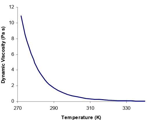
Figure 1. Glycerol Viscosity vs. Temperature. ...3
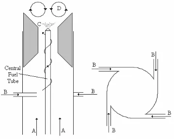
Figure 2. Side and top view burner diagram...6
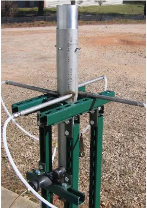
Figure 3. Picture of the swirl burner. ...7
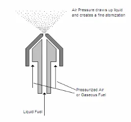
Figure 4. Diagram of siphon air atomizing nozzle. ...9
Figure 5. Diagram of the top of the burner with flame enclosure, not to scale. ...11
Figure 6. Pictures of the burner running on pure glycerol...12
Figure 7. Glycerol’s thermal decomposition into acrolein. ...13
Figure 8. Structure of a DNPH Molecule, and a drawing of a DNPH Cartridge...14
Figure 9. Reaction of DNPH with acrolein to produce a DNPH Derivative and water ....14
Figure 10. Diagram of the extraction system...16
Figure 11. Picture of different grades of glycerol...19
Figure 12. Aldehyde concentration measurements...22
Figure 13. Temperature and CO/CO2 ...24
Figure 14. Picture of the black residue ...25
Figure 15. Picture of the residue found on the top of the flame enclosure ...26
Figure 16. Original burner design...28
Figure 17. Schematic of the burner with glycerol preheating and flame enclosure. ...31
Figure 18. Drawing of the Salamander Burner...34
Figure 19. Salamander burner before (left) and after (right) modifications. ...37
Figure 20. Diagram of the redesigned fuel tube and nozzle. ...39
LIST OF TABLES
1 INTRODUCTION
Glycerol, or Propane-1,2,3-triol is a compound used as a component in medical and pharmaceutical products, livestock feeds, lubricants, food additives, plastics, nitroglycerine, antifreeze, and fabrics. Glycerol is currently produced during saphonification of fats (soap making) and transesterification of triglycerides (biodiesel production). While pure glycerol is a marketable commodity, the recent popularization and growth of the biodiesel industry has flooded the market with an excess supply of glycerol. This has caused a substantial continual drop in the price of glycerol.
Biodiesel is produced from the transesterification of triglycerides (most commonly from vegetable oils or animal fats) via the following reaction.
and other small concentrations of contaminants such as proteins or soaps, depending on the feedstock. Excess alcohol is due to the common practice of adding more alcohol and catalyst than is stoichiometrically required, in order to decrease reaction times. While it is often cost effective to recover the alcohol for reuse, it is difficult and expensive to purify crude glycerol for resale (i.e. remove water, catalyst, salt and other impurities), and continually falling pure glycerol prices make it even more cost prohibitive. Some biodiesel operations have
successfully used crude glycerol as a livestock feed additives and fertilizers. Still many, such as Imperium Renewables (soon to be the largest biodiesel producer in North or South
America) currently pay to have glycerol shipped away to landfills. Thus, a worldwide initiative has begun to find new value added uses for waste glycerol (Van Gerpen, 2004). The work for this project has been partially sponsored by Dr. Stephen Peretti and Dr. Henry Lamb’s Department of Energy grant for research into alternative uses for crude glycerol. Glycerol combustion could also be a key factor in the development of new biodiesel processes, such as the Centia process (co-invented by Dr. W. L. Roberts and Tim Turner), which require large thermal inputs and also creates waste glycerol.
It has been said that combustion of glycerol “would be an elegant solution, if it
Glycerol is much more difficult to burn than conventional hydrocarbon fuels. While glycerol contains significant energy, its energy density is much less than conventional hydrocarbon fuels. One kilogram of glycerol contains roughly 16 MJ of chemical energy, in comparison to kerosene, which has 42.8 MJ/kg, or gasoline with 44.4MJ/kg. Glycerol is also a highly viscous liquid at room temperature, with a kinematic viscosity over 450 centistokes, compared with water which has a kinematic viscosity of 1 centistoke. Kerosene has a kinematic viscosity of 2.71 centistokes, and gasoline falls between 0.46 to 0.88 centistokes, depending on the grade. The high viscosity of glycerol makes it impossible to atomize cold pure glycerol using standard nozzles found in fuel oil burners. It should be noted that waste glycerol from biodiesel production may contain some alcohol which will lower the viscosity, but many biodiesel producers prefer to evaporate and recover the alcohol from the glycerol for reuse. Glycerol can also be heated to dramatically reduce its viscosity, as seen in Figure 1 (DIPPR, 2005).
0 2 4 6 8 10 12
270 290 310 330
Temperature (K)
Dynamic V
iscosity (P
a s)
Perhaps the biggest difficulty in burning glycerol is its high auto-ignition temperature. Glycerol has an auto-ignition temperature of 370oC, as compared to 280oC for gasoline and 210oC for kerosene (DIPPR, 2005). This represents a higher activation energy for the oxidation reaction. Whereas a standard fuel like kerosene can be ignited with a single spark and hold a flame in ambient air, glycerol under the same conditions will not ignite. Even if a blowtorch is lowered into an open spray of glycerol, droplets passing through the blowtorch flame will burn, but will not give off enough energy to cause a continuous combustion reaction.
Another factor that has prevented the majority of the biodiesel producing community from attempting to burn glycerol is the fear of toxic emissions, particularly acrolein.
Acrolein is a known thermal decomposition product of glycerol when heated above 280oC (EPA, 2003) which is well below the auto-ignition temperature of glycerol. It is toxic at very low concentrations, roughly 2 ppm. Some studies have suggested human health hazards as low as 0.09 ppm (EPA, 2003). Because acrolein is dangerous even at such low
energy of glycerol by volume, the glycerol requires 1/3 as much atmospheric oxygen to react completly.
It should also be noted that there are other companies marketing burners that claim to burn crude glycerol. Columbia’s WL60 Waste Oil Burner has been advertised to be capable of operating with glycerol as a fuel (www.columbiaburner.com). UkrBioDiesel is a
Ukrainian company marketing a burner specifically intended to burn glycerol
2 APPARATUS
The burner design used in the following experiments and shown schematically in Figure 2 and pictorially in Fig 3, is modeled off the swirl burner used by Ruey-Hueng Chen (Chen and Driscoll, 1990; Chen, 2006; Feikema et al, 1991; Tangirala et al, 1987). All physical dimensions have been doubled to accommodate a liquid fuel spray nozzle.
Figure 3. Picture of the swirl burner.
Air is injected both axially from the bottom (A) and tangentially through the 4 side ports (B). The two air streams mix to form a swirling velocity profile, which flows around the central fuel tube. The flow can be characterized by the nondimensional swirl number, defined as
2
d G
G
z
ϕ
=
Where Gφ is the mass flux of axial air and Gz is the mass flux of tangential air. A swirl
number of zero represents a conventional co-flow burner with no swirl, and a swirl number of five represents a relatively high swirl flame. At the top of the burner, fuel is sprayed (C) and mixed with the swirling air, and burns. At this point, the 60o cone in the burner
geometry creates an expansion in the air flow. The combination of swirling air and the low pressure zone created by the expansion causes the flame to form a recalculation zone (D), where combustion gasses are pulled from the outside of the flame back to the center. As the swirl number is raised, the flame height will decrease dramatically (Turns, 2000).
Figure 4. Diagram of siphon air atomizing nozzle.
To further strengthen the flame recirculation zone above the spray nozzle and to provide a significantly hotter environment for the glycerol flame, an insulated metal
enclosure is placed around the flame. To accomplish this, the radiation shield of a kerosene forced air heater was wrapped in insulation and placed over the flame. The flame enclosure features two top plates, which allow combustion gasses to be exhausted while still
completely surrounding the flame. For demonstration and analytical purposes, an alternative flame enclosure was built with a 1” x 9” vertical window. The window was constructed from three fused quartz microscope slides (fused quartz can be safely heated to 1500oC) held in a metal bracket, which is fastened to the flame enclosure. Using the windowed flame
enclosure, the glycerol flame was observed to have a faint blue color (attributed to
point, the surrounding metal radiates bright red light, making it difficult to photograph the glycerol flame.
3 MEASUREMENTS
Several experiments were conducted to determine if glycerol combustion in the final burner design can be considered safe in terms of environmental pollutants and human health. Emissions tests were performed to measure CO/CO2, unburned hydrocarbons, and
temperature in the exhaust gas. These tests were performed using several grades of glycerol purity. Testing was also conducted to detect and quantify aldehydes and ketones present in the burner’s emissions.
3.1 Aldehyde and Ketone testing
The primary objective of these experiments is to determine the concentration of acrolein and other aldehydes in the exhaust gas during glycerol combustion. Acrolein in particular requires measurement down to very small detection limits, as the toxic limit is known to be 2 ppm. Acrolein is also of particular interest in glycerol combustion because it is a known thermal decomposition product of glycerol, as illustrated in Figure 7.
Figure 7. Glycerol’s thermal decomposition into acrolein.
2,4-Dinitrophenyl-hydrazine, also known as Brady’s reagent or by the initials DNPH, is a chemical commonly used for the detection of ketones and aldehydes. DNPH cartridges, containing a porous plug of DNPH, can be purchased. The chemical structure is as shown in Figure 8.
Figure 8. Structure of a DNPH Molecule, and a drawing of a DNPH Cartridge.
In order to detect and quantify small concentrations ketones and aldehydes, exhaust gas is pulled through a small cartridge containing a porous plug of DNPH. Any aldehydes or ketones in the exhaust will be captured in the above reaction and held in the cartridge while other gasses flow through. The DNPH plug in the cartridge can later be eluted (dissolved) in acetonitrile. The solution is put through a High Pressure Liquid Chromatography (HPLC) analysis to quantify the mass of any particular DNPH Derivatives present. This mass measurement compared with the volume of exhaust gas that was previously pulled through the cartridge can yield the concentration of corresponding aldehydes, which were originally in the exhaust (Madden, 2007; Ho and Yu, 2004).
In designing an extraction system, where exhaust gas will be pulled through the DNPH cartridge, temperature must be considered. The gas pulled through the cartridge must not at a temperature above 100oC, due mainly to the plastic casing of each cartridge. Thus the exhaust gas drawn directly from the flame must pass through a cooling apparatus before it reaches the cartridge.
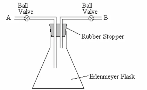
Figure 10. Diagram of the extraction system.
In the system shown in Figure 10, the one liter Erlenmeyer flask is used to allow the hot gasses time to cool to below 100oC. The volume of the flask and tubing is a known, fixed quantity (1.1 L in this case). Instead of pulling gasses directly from the flame to the cartridge, which would require controlling the flow rate and the flow time through the system, the flask is used to hold a fixed volume of gas, which can then be run through the cartridge at any rate. The procedure for using the extraction system is as follows.
gas inside the flask and tubing. The burner can now be turned off and the extraction system can be moved.
3. A compressed air source is attached to point A, and a blank DNPH cartridge is attached to point B. Both ball valves are opened, and the compressed air pushes the exhaust gas out of the flask through the cartridge. Flow should not exceed 1 SLPM in order to avoid pushing the rubber stopper loose from the flask.
Because the volume of exhaust gas contained in the system is fixed, it is unnecessary to precisely control the flow rates and flow times. Although the analysis works under the assumption that there are negligible levels of aldehydes present in the compressed air, a sample is taken without using the burner as a reference sample. To test samples using HPLC, each cartridge is eluted in acetonitrile. The acetonitrile is injected into one end of the
cartridge and flows out the other end with the DNPH dissolved into it. This solution is then injected into the HPLC unit. As stated earlier, the HPLC test does not look for aldehyde species, but rather seeks to detect the DNPH derivative species for each aldehyde species.
An additional concern is that the aldehydes may potentially be condensed out of the combustion gas when cooled. Indeed, a thin fog of water (a byproduct of any hydrocarbon combustion reaction) can be seen on the sides of the Erlenmeyer flask when the combustion gasses are extracted in Step 1 described above. This condensate should also be tested for aldehydes. To do this, after Step 3 is complete, the sides of the flask are rinsed with a small volume of acetonitrile (~5mL). This mixture of condensate and acetonitrile is then collected and injected through a second, fresh DNPH cartridge. The DNPH dissolves in the
of acetonitrile, DNPH, and condensate flows out the other end of the cartridge and is collected to be tested using HPLC. The empty cartridge is discarded.
This offers only qualitative data of the presence or absence of aldehydes in the condensate. The amount of air that has passed through the beaker is not precisely measured, and it is not known what percentage of water was condensed out of the exhaust gas. As shown in Table 1, all four species detected in the HPLC tests have a much higher saturation pressure than that of water, and it is unlikely that they would condense out of the vapor unless it contains extremely high concentrations of the substance. However, as all four are soluble in water, the possibility of aldehyde molecules being carried into the condensate with water must me considered. It is also important to note that not all of the
condensate/acetonitrile mixture can be recovered from the beaker without advanced methods.
Table 1. Saturation pressures of aldehydes in room temperature air
Psat (kPa)
Formaldehyde 514.01
Acetaldehyde 115.84 Acrolein 17.5 Acetone 36.31 Water 3.142
3.2 CO, Temperature, NOx, and UBHC testing
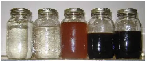
To supplement the aldehyde exhaust data, measurements of temperature, unburnt hydrocarbons, and CO/CO2 are taken using an ECOM AC portable gas analyzer. These three data points are used as rough measures of combustion efficiency. For consistency and ease of use, the probe of the detector is consistently placed on the same spot at the top of the burner enclosure to extract samples. Data is recorded from the digital readout of the gas analyzer after the flame has been given time to reach steady state. This method was used to compare burner emissions using five different qualities of glycerol: pure laboratory grade glycerol, pure glycerol mixed 80/20 volumetrically with water, glycerol from the
transesterification of virgin soy, glycerol from the transesterification of waste fryer oil, and glycerol from the transesterification of chicken fats. Figure 11 shows a picture samples of these five grades of glycerol purity. As a reference, measurements were also taken on kerosene, methane, and propane flames.
4 RESULTS AND DISCUSSION
The primary result of this project is the final design of the modified swirl burner, which proves that it is possible to effectively burn glycerol for process heating. In experimenting with numerous redesigns of the swirl burner, it has become clear that two important factors are necessary for glycerol combustion: preheating and recirculation. Several failed designs demonstrated that while the auto-ignition temperature of glycerol is 370oC, the burner enclosure must be in the range of 1000oC for the burner to be effective. This is because each droplet experiences only a short time inside the hot environment where it must be heated, combusted, and then transfer heat back to the environment before exiting as exhaust gas. Thus, the role of recirculation in the flame is to extend the period of time in which each glycerol particle spends in the hot combustion environment. A diagram of the final burner design can be found in Figure 6. In this design, a high swirl flame and the shape of the burner enclosure are used to enhance recirculation. The burner is operated by
preheating the combustion chamber with a propane flame before switching to a pure glycerol flame through the following systematic instructions.
3. Gradually increase the airflow through the nozzle from zero to roughly 18 SLPM. This is the most air that can be put through the nozzle without blowing out the propane flame
4. Place the metal flame enclosure over the propane flame. Wait 5-10 minutes for the metal to heat up, or until the majority of the top of the flame enclosure begins to glow bright red.
5. When the flame enclosure is hot enough, begin pumping the glycerol to the nozzle at roughly 1 gram per second. Monitor the glycerol flow rate with the scale. It will be clear when the glycerol is spraying into the flame, as the flame will grow considerably and suddenly with two fuels supplying energy.
6. Increase the nozzle air flow rate to 30 SLPM.
7. Close the valve for propane flow. The flame should continue to burn exclusively fueled by glycerol.
Once the methods had been optimized, emissions were performed on the burner, as described earlier. Results from the aldehyde tests showed that acrolein was not present at any dangerous levels in the exhaust. The highest detected level of acrolein in any test was 17.5 ppb (parts per billion). Acrolein is not dangerous to human health at levels below 90 ppb. HPLC testing of the condensate collected from exhaust gasses also were unable to detect acrolein above the HPLC’s lower limit of 11.5 ng, which would be equivalent to less than 1 ppb.
2 displays the equivalence ratios used in these fuels and the adiabatic flame temperatures of each mixture, noting that the airflow was constant throughout.
Table 2. Comparison of flowrates for each fuel tested
Fuel
Flowrate Equivalence Ratio
Adiabatic Flame
Temp
Glycerol 1 gal/hr 0.8 1985 K
Kerosene 0.3 gal/hr 0.6 1709 K
Propane 20.7 SLPM 1 2287 K
Methane 8.2 SLPM 1 2246 K
Emission tests were also conducted using an ECOM AC emissions analyzer to compare different grades of glycerol. All tests revealed undetectable levels of nitrous oxide compounds and unburned hydrocarbons. However the system used is not noted for high precision in NOx or UBHC measurements. The emissions analyzer was mainly used to measure temperature and carbon monoxide, both as indicatiors of combustion efficiency. Measurements were taken on pure lab grade glycerol, pure glycerol mixed with water at an 80/20 volumetric ratio, glycerol from the transesterification of virgin soy oil, glycerol from the transesterification of waste fryer oil, and glycerol from the transesterification of chicken fats. Unsurprisingly, the quality and purity of the glycerol affected the combustion efficiency of the burner. Glycerol from virgin and waste soy oil showed lower temperature and higher CO levels than the lab grade glycerol, but still burned well. Glycerol from animal fat burned with a lower combustion efficiency and temperature than any other fuel tested.
Glycerol mixed with water burned at a lower temperature, however the levels of CO/CO2 were reduced by 84%. The temperature drop is due to the enthalpy which must consumed to heat and evaporate the water. The dramatic drop in carbon monoxide can be explained through previous studies in the explosion limits and oxidation of carbon monoxide. Glassman writes, “The rate of CO oxidation in the presence of species such as water is
spray nozzle to mist water or steam into the flame enclosure. All measurements are displayed in Figure 13.
Figure 13. Temperature and CO/CO2 for lab grade glycerol, glycerol mixed with water,
glycerol from transesterification of virgin soy oil, glycerol from transesterification of
used fryer oil, and glycerol from the transesterification of chicken fat.
Figure 14. Picture of the black residue, which collected on the venturi from burning animal fat derived glycerol.
4 DISCARDED BURNER DESIGNS
The current physical design of the burner used for all data presented in this report is the result of a long trial and error design process. As the difficulties of achieving glycerol combustion became more apparent, the structure of the burner and its components were continuously altered to eventually find a working design. In fact, it was not until many iterations had been tested that any burner was able to achieve sustainable glycerol combustion. While many critical aspects of past designs have now been discarded, it is important to note all intermediate burner designs and analyze their improvements and faults.
Figure 16. Original burner design.
tangential air flow to axial air flow (the swirl number) is raised, the flame height will decrease dramatically.
This burner worked well for conventional liquid fuels such as kerosene or ethanol. The behavior with respect to swirl number was comparable to that of Chen’s burner. However when it glycerol was used, it became quickly apparent that the pressure driven nozzles could not spray a fluid with such a high viscosity. Experiments were performed mixing glycerol with ethanol to lower the viscosity, but they revealed that up to 50% ethanol was needed to thin the mixture to viscosities below 16 centistokes as required to achieve good atomization. It was decided that this was too high of a mixture requirement to be economically viable, thus another solution was needed.
Heating the glycerol to higher temperature was the second method tested. The glycerol would need to be heated to 91oC to drop its viscosity below 16 centistokes, which is considered the upper limit of viscosity the nozzle can accommodate. To achieve this, a copper coil was added to the glycerol line to be used as a heat exchanger. Boiling water heated on a hot plate would heat the coil, which would in turn heat the glycerol to 100oC. Glycerol would be pumped through the submerged coil and heated before being sent to the nozzle. Early tests showed that when fed directly from the coil to the nozzle, the heated glycerol would atomize well. However when the same coil was added at the fuel entry point at the bottom of the burner, the glycerol did not spray.
diameter and length of the vertical fuel tube. Thus cold air flows around the outside of the fuel tube, providing ample chance for convective heat loss to the air. At this point, glycerol simply dripped down the nozzle in a thick stream, indicating that too much heat had been lost causing the viscosity to increase.
It was decided that simply insulating the central fuel line would not be enough to keep the fuel from cooling during its path from the heating coil to the nozzle. The fuel tube had thick stainless steel walls, due to geometric constraints. The fuel tube would have to be actively heated before the glycerol was sent through. Additionally, the tube and heating source should be insulated to avoid heating the swirling air, as higher temperature air would have a lower density and change the velocity and Reynolds number. Both the active heating layer and the insulation layer were to be kept to the minimum possible thickness, so as to avoid creating unnecessary obstructions for the swirling air.
blowtorch aimed directly into the middle of the spray, the glycerol would smoke but not ignite into a flame. This is due to the previously mentioned high auto-ignition temperature of glycerol. It was determined that a hot environment was needed for the glycerol combustion to take place in.
The first attempt to create a high temperature environment came in the form of a simple pipe placed at the top of the burner and insulated. The pipe would act as an insulated chimney inside which combustion could occur. The inspiration for this design was that of kerosene space heaters known as Salamander Burners. These burners spray kerosene inside a metal enclosure where radiation from the hot walls is reflected back at the flame. In this case, kerosene would be used as a starter fuel to heat the walls of the chimney, and then glycerol would be sprayed into the same hot environment and burnt. A schematic of the process is displayed in Figure 17.
Figure 17. Schematic of the burner with glycerol preheating and flame enclosure.
interval of glycerol combustion indicated that burning in a preheated flame enclosure was the right track to pursue. There were several problems with the design that quickly became apparent.
• Since there was only one nozzle through which kerosene and glycerol needed to pass through, the burner needed to be lit with kerosene. Later the pump’s supply line would be switched over to glycerol. At no point could both kerosene and glycerol be burned at the same time, and the transition could be made only once in each test.
• While the burner could be run on kerosene with all pipes cold, the fuel tube had to be heated before glycerol could be sent through. Due to the nature of the
transition from kerosene, the fuel tube had to be heated to 100oC while kerosene was still flowing through it, just before the transition. Kerosene boils around 147oC, so it was important to carefully monitor the temperature.
• With the kerosene burning, it took roughly thirty minutes of heating for the chimney pipe to rise to the 800 -1000oC temperature range that was necessary for the glycerol to burn.
that the air’s swirl number was being reduced. It became clear that in the small space between the fuel tube and the venturi (roughly ½ inch without the wrap) even a small physical obstruction could have a major negative effect on the flow pattern.
• When glycerol began spraying into the flame, the temperature of the chimney pipe, monitored by thermocouples, would begin to drop. When the temperature dropped below roughly 600oC, the flame would die out and the glycerol would simply smoke. It was apparent that while the hot environment caused the glycerol to burn, the evaporation and ignition of the glycerol droplets were draining more energy form the system than the flame was contributing back to the chimney walls.
Of the above issues, the final was considered the most critical. The burner would have no value if a flame could not be sustained indefinitely. Inspiration was once again taken from the design of the salamander burner, which feature a circular metal plate at the exit of the flame enclosure to enhance the recirculation zone in the flame. Some form of a flow obstruction was needed to increase the residence time of each fuel particle inside the hottest section of the chimney. The intention was for each fuel particle to remain inside the hottest region of the flame enclosure for the longest possible time, increasing the fuel’s chances of burning completely and transferring heat back to the incoming, evaporating glycerol before being exhausted from the top of the chimney.
and convex metal plates, wire mesh, and donut shaped plates. All these geometries were tested at a variety of heights above the flame and with different diameter chimneys, all with varying results. However, the behavior that held constant was that after some period of time with glycerol spraying into the flame (2-15 min depending on the geometry and placement) the flame would cool and extinguish.
Figure 18. Drawing of the Salamander Burner.
• Two sensors monitor the flame. A high limit temperature sensor at the exhaust exit acts as a cutoff switch to prevent the casing from overheating. A CAD sensor detects light inside the radiation shield, to act as a cutoff switch if the burner runs out of fuel.
• In contrast to the nozzles previously used on the swirl burner, which require the fuel to be pumped at high pressure to get good atomization, the salamander burner uses a Siphon Air Atomizing Nozzle for low viscosity fuels. A siphon nozzle uses pressurized air both to draw fuel to the nozzle (eliminating the need for a fuel pump) and to atomize the fuel into a fine spray. A small air pump powered by the same shaft as the burner’s fan provides pressurized air to the nozzle.
The most interesting aspect of the salamander burner was the siphon nozzle. It was discovered that cold glycerol could be atomized with the siphon nozzle with two
augmentations. First, a much higher air pressure and flow rate through the nozzle would be needed (30 SLPM compared to 2-4 SLPM for kerosene). Second, the high viscosity of the glycerol prevented the nozzle from pulling fuel through the line, and thus the glycerol would need to be pumped externally. Both modifications would be relatively easy to implement with the existing fuel pump and air compressor.
then be applied to the swirl burner. The modifications made to the salamander burner were as follows (depicted in Figure 19).
• The controls were rewired to bypass the CAD sensor and high temperature sensor. This also allowed independent control of the spark ignition and the fan/air pump motor.
• Two siphon nozzles replaced the original single nozzle. The first nozzle sprayed kerosene drawn from an outside container and powered by the burner’s air pump. The second nozzle sprayed glycerol pumped from another container, powered by much higher air pressure from the building’s compressor.
• The flame enclosure was moved further downstream from the fan to make space for the two nozzle systems.
• All plastic and rubber parts and tubes were removed or replaced with metal, due to the higher temperatures the burner would experience.
Figure 19. Salamander burner with top shell removed before (left) and after (right) modifications.
This (highly modified) salamander burner design is notable for being the first in the duration of this project to reliably produce a sustained glycerol flame. The most important factors distinguishing it from previous designs were the ability to independently control the kerosene and glycerol sprays, and also the ability to adjust the flow rates of both fuels in real time. In this burner (and future designs), the glycerol is sprayed at a volumetric flow rate roughly twice that of kerosene with the same air supply. This is due to the lower energy content and the lower oxygen requirements of glycerol oxidation. Glycerol provides roughly a third the energy of an equal volume of kerosene, and requires roughly half the oxygen to burn.
The modified salamander burner was used to take preliminary aldehyde
The first weakness was that the siphon nozzles were prone to clogging. Whereas the previous pressure driven nozzle were fitted with a small filter, the siphon nozzles were not. The fuel passes through a small opening, roughly 50 microns in diameter, which can easily be plugged with a small grain of sand or dust. This was regarded as a minor flaw at the time, as the nozzles are easy to disassemble and clean. Later designs added a fuel filter
downstream of the glycerol pump. Clogging is still a major concern if the burner is to be used to burn glycerol made from transesterification of fryer oils, which may contain large amounts of sediments.
Figure 20. Diagram of the redesigned fuel tube and nozzle.
Figure 21. Original (left) and new (right) placement of fuel tube relative to burner body.
the flame enclosure was hot enough, glycerol would be pumped to the nozzle and pressurized methane (in place of pressurized air) would atomize the glycerol and the ignite it. As the glycerol begins to burn, the pressurized air would gradually replace the pressurized methane as the atomization medium, and the flame would run on pure glycerol.
Although supplying gaseous fuel directly through the spray nozzle was viewed as a somewhat elegant solution, it did not work well in practice. As earlier stated, relatively high volumetric flow rates (roughly 30 SLPM) of air or any gas through the nozzle are necessary to atomize glycerol. These high flow rates are pushed through a small opening at the tip of the nozzle (d = 0.075 in), and thus a very high velocity (Reynold’s number = 4800). When tested, it was found that the methane could create a strong flame when flowed slowly through the nozzle, but as the flow rate increased, the velocity would be too high and the flame would blow out. This can be explained with an examination of the blow off limits for premixed methane and propane flame. Both methane and propane have similar blow off limits for flow rate, and for a premixed methane or propane flame, a flow with Reynolds number above 26 could be expected to blow off. Methane and propane flames were tested under many conditions, with varying flow rates and air mixtures (Lewis, 1987). Whenever the flow rate through the nozzle rose above 12 SLPM, the flame would extinguish.
5 CONCLUSIONS
• Using the final design of the modified swirl burner, glycerol can be effectively combusted for disposal of waste glycerol and recovery of thermal energy.
• Aldehyde tests show that acrolein is not present to any dangerous degree in glycerol combustion exhaust gas. Acrolein is not present above the detection limits at ppb level.
• Aldehyde tests show that formaldehyde and acetaldehyde exist in higher
concentrations in glycerol combustion exhaust than in that of kerosene or propane flames.
• Exhaust emissions tests show that glycerol from various sources and feedstocks can burn without unsafe levels of carbon monoxide, unburnt hydrocarbons, or nitrous oxides. Tests show strong combustion efficiency through quantification of CO/CO2 below 10%.
• Carbon monoxide emissions are reduced by over 80% by mixing water into glycerol prior to combustion at an 80/20 glycerol/water ratio.
6 REFERENCES
Chen, R. H., Driscoll, J.F., “A Comparison of Bluff-Body and Swirl-Stabilizing Flames,” Combust. Sci. and Tech. Vol. 71, 197-217 (1990).
Chen, R. H. (2006) private communication.
DIPPR Project 801 – “Full Version Evaluated Standard Thermophysical Property Values,” Design Institute for Physical Properties, Department of Chemical Engineering, Brigham Young University, Provo, Utah, (2005).
EPA, “Toxicological Review of Acrolein,” CAS No. 107-02-8, EPA/635/R-03/003, (2003). Feikema, D., Chen, R.H., Driscoll, J.F. “Blowout of Nonpremixed Flames: Maximum
Coaxial Air Velocities Achievable, with and without Swirl,” Combustion and Flame 86, 347-358 (1991).
Glassman, Irvin., Combustion Third Edition, 72-76, Academic Press, Inc., San Diego, California (1996).
Hobbs, Alex. (2006) private communication.
Lewis, Bernard., Von Elbe, Guenther., Combustion, Flames and Explosions of Gases Third Edition, 239-274, Academic Press, Inc., London, England (1987).
Madden, M., (2007) private communication.
Ho, S.H.H., Yu, J.Z., “Determination of Airborne Carbonyls: Comparison of a Thermal Desorption/GC Method with the Standard DNPH/HPLC Method,” Environ. Sci. Technol., 38, 862-870, (2004).
Stembridge, J., Delavan Inc., (2006) private communication.
Tangirala, V., Chen, R.H., Driscoll, J.F., “Effect of Heat Release and Swirl on the
Recirculation within Swirl-Stabilized Flames,” Combust. Sci. and Tech, Vol. 51, 75-95 (1987).
Turns, Stephen R., An Introduction to Combustion Concepts and Application Second Edition, McGraw-Hill Companies, Inc. United States of America, (2000). Van Gerpen, J., “Biodiesel Production Technology,” NREL/SR-510-36244, Golden,
Colarado. http://www.osti.gov/bridge, (2004).
www.bioking.nl
http://www.ukrbiodiesel.com.ua/en/biodiesel-glycerine.htm
7 APPENDEX
Table 3. Burner operating conditions for DNPH measurements.
Fuel
Flowrate Equivalence Ratio
Adiabatic Flame
Temp Flowrate Axial Air Air Flowrate Tangential Nozzle Air Flowrate
Glycerol 1 gal/hr 0.8 1985 K 30 SLPM 140 SLPM 30 SLPM
Kerosene 0.3 gal/hr 0.6 1709 K 30 SLPM 140 SLPM 1-2 SLPM
Propane 20.7 SLPM 1 2287 K 30 SLPM 140 SLPM 0 SLPM