RAPIDLY DISSOLVABLE PRINTMICRONEEDLES FOR THE TRANSDERMAL DELIVERY OF
THERAPEUTICS
Katherine Anne Moga
A dissertation submitted to the faculty of the University of North Carolina at Chapel Hill in partial fulfillment of the requirements for the degree of Doctor of Philosophy
in the Department of Chemistry.
Chapel Hill 2015
Approved by:
Joseph M. DeSimone James W. Jorgenson
ii © 2015
iii ABSTRACT
Katherine Anne Moga: RAPIDLY DISSOLVABLE PRINTMICRONEEDLES FOR THE TRANSDERMAL
DELIVERY OF THERAPEUTICS
(Under the direction of Joseph M. DeSimone)
In recent years, microneedle devices have become an attractive method to overcome the diffusion-limiting epidermis and effectively transport therapeutics to the body. Microneedles are arrays of micron-sized projections that pierce the skin to administer drugs, manually creating channels for the passage of a therapeutic. Biodegradable or water-soluble microneedles are of high interest due to their safety, low device complexity, and ability to deliver agents of nearly any size. The main limitation of biodegradable microneedles is their arduous manufacturing, requiring long vacuum and centrifugation steps to fill a mold. The fabrication of microneedles via the highly scalable and reproducible Particle Replication in Non-wetting Templates
(PRINT®) platform has great promise to expand this growing field by eliminating these obstacles to clinical translation.
Herein, the fabrication of 100% water-soluble PRINT microneedles on flexible substrates is demonstrated. The ability of these devices to load therapeutics of nearly any size, shape, and surface charge – while maintaining the function of the cargo throughout – has been shown through the encapsulation of small molecule dyes, proteins, and hydrogel nanoparticles. PRINT microneedle devices were seen to pierce skin and transport cargo in both ex vivo and in vivo
iv
permeation kinetics of the small molecule, protein, and particulate drug surrogates through full thickness murine skin were investigated; microneedles greatly increased the delivered dose of small molecules when compared to topical formulations. Both proteins and nanoparticles were seen to deposit in the skin after application with PRINT microneedles, but the permeation kinetics through this tissue slowed as cargo size increased. PRINT microneedle device
application in vivo was optimized on nude murine models, and it was shown that these devices efficaciously deliver small molecule drug surrogates to living tissue. The ability of the PRINT microneedles pierce excised human skin was shown, highlighting the capability of the
technology to transition into a clinically-relevant product. Finally, PRINT microneedle devices were adapted to two therapeutically-relevant systems: the delivery of butyrylcholinesterase as a countermeasure against nerve gas overexposure, and the treatment of skin-invading breast
cancers by introducing chemotherapeutics via microneedles. Therefore, efficacious water-soluble microneedle devices have been made reproducibly and quickly via PRINT technology,
v
ACKNOWLEDGEMENTS
I have a great many people to thank for their contributions, support, and guidance over the years that made the pursuit of my doctorate possible. First, I would like to thank my advisor, Dr. Joseph M. DeSimone, for the opportunity to work in such an inspiring environment. You have challenged me to be a better researcher, mentor, and teacher, and for that I will be eternally grateful. To those who directly contributed to the collection of data presented herein – Dr. Lissett Bickford, Dr. Robert Geil, Dr. Ashish Pandya, Dr. Richard Blackmon, Cassie Caudill, Ashley Johnson, Erin Wilson, Christine Archuleta, and Sarah Gagné – I literally could not have done this without your help. In particular, I would like to acknowledge Cassie for her tireless efforts in the push to finish our experiments (and for editing my dissertation); it has been a pleasure to see this to the end with you! Christine and Sarah, thank you for opening my eyes to mentoring and trusting me during your undergraduate research experiences, for you have truly motivated me to pursue a career doing the same. Additionally, I would like to thank Dr. Chris Luft, Dr. Jillian Perry, Dr. Charles Bowerman, and Dr. Stuart Dunn for using their experience and expertise to help me design experiments. I cannot tell you all how much I learned from each of you.
vi
Reduction Agency, Pioneer, Center for Cancer Nanotechnology Excellence, and the UNC Department of Chemistry for funding.
On a personal note, I have many people to thank who supported me during this process. To my professors at Ashland University, particularly Dr. Perry Corbin and Dr. Rebecca Corbin, thank you for suggesting I give graduate school a shot; I am only here because of you. All members of the DeSimone Lab, past and present, I thank you for making long days in lab and time away from the bench so enjoyable. I am only the professional I am today because of conversations with Crista Farrell, Vicki Haithcock, and Dr. Chris Luft; thank you for supporting me and encouraging me to reach my goals.
I am beyond grateful to my family and friends for the love and support they have provided me from near and far. To my parents and grandparents – thank you for always
encouraging me to go after my dreams and being 1000% confident that I could achieve them. I know living 500 miles apart has not been easy, and I am so grateful that you are always willing to visit your “vacation home.” To my sister, Vicki – thanks for being my rock; you always know how to make me laugh, and your support and friendship means the world to me. To my Stow, Ashland, and UNC friends turned family – especially Jenny, Amanda, Michelle, Aubree, Stacey, and Katie – thank you for keeping me sane during graduate school with visits, calls,
vii
TABLE OF CONTENTS
LIST OF FIGURES…..………...…………... xii
LIST OF TABLES…………..………...………...…….…... xix
LIST OF SCHEMES…………..………...………...……..xxi
LIST OF ABBREVIATIONS AND SYMBOLS………...………...……....xxii
CHAPTER 1: MICRONEEDLE TECHNOLOGY FOR THE ADVANCEMENT OF TRANSDERMAL DRUG DELIVERY………...……...……...………....…....1
1.1 Challenges in Drug Delivery ... 1
1.2 Transdermal Drug Delivery ... 3
1.3 Microneedles ... 7
1.3.1 Types of Microneedles ... 8
1.3.2 Biodegradable/Water-soluble Microneedles ... 11
1.4 Particle Replication In Non-wetting Templates (PRINT®) Technology ... 14
1.5 Summary and Hypothesis... 17
1.6 References ... 18
CHAPTER 2: FABRICATION AND CHARACTERIZATION OF PRINTMICRONEEDLE PATCHES…………...…..22
2.1 Introduction ... 22
2.2 Results and Discussion ... 24
2.2.1 Master Template Fabrication ... 26
2.2.2 PDMS Replica Fabrication ... 28
viii
2.2.4 Microneedle Fabrication ... 29
2.2.5 Drug Surrogate Loading into Microneedles ... 32
2.3 Conclusions ... 47
2.4 Experimental ... 48
2.4.1 Master Template Fabrication ... 48
2.4.2 PDMS Replica Fabrication ... 49
2.4.3 PFPE Synthesis and Mold Fabrication ... 49
2.4.4 Substrate Development ... 51
2.4.5 PRINT Particle Fabrication and Characterization ... 52
2.4.6 Microneedle Fabrication ... 54
2.4.7 Microneedle Characterization ... 56
2.5 References ... 59
CHAPTER 3: EX VIVO AND IN VIVO DELIVERY OF DRUG SURROGATE CARGOS VIA PRINTMICRONEEDLES...62
3.1 Introduction ... 62
3.2 Results and Discussion ... 65
3.2.1 Administration of PRINT Microneedles to Ex Vivo Murine Skin – Penetration Studies with Optical Coherence Tomography ... 65
3.2.2 Delivery of Drug Surrogate Cargo to Ex Vivo Murine Skin ... 68
3.2.3 Delivery of Drug Surrogate Cargo to In Vivo Murine Models ... 84
3.2.4 Delivery of Drug Surrogate Cargo to Ex Vivo Human Skin ... 89
3.3 Conclusions ... 90
3.4 Experimental ... 91
ix
3.4.2 Optical Coherence Tomography ... 92
3.4.3 Skin penetration studies with rhodamine-loaded microneedles (Murine and Human) ... 93
3.4.4 Franz Diffusion Cell Studies with Rhodamine Pre-Microneedle Solution ... 94
3.4.5 Application of Protein and Particle-Loaded Films (Controls) to Ex Vivo Murine Tissue ... 95
3.4.6 Franz Diffusion Cell Studies with Microneedle Patches (All Cargos) ... 96
3.4.7 In Vivo Application of Microneedles to Nude Mice ... 98
3.5 References ... 100
CHAPTER 4: PRINTMICRONEEDLES FOR THE DELIVERY OF BUTYRYLCHOLINESTERASE TO COMBAT ORGANOPHOSPHATE OVEREXPOSURE...103
4.1 Introduction ... 103
4.2 Results and Discussion ... 106
4.2.1 Fabrication and Characterization of PRINT Microneedles Incorporating BuChE ... 106
4.2.2 Ex Vivo Permeation Studies with Microneedles Incorporating Free BuChE ... 117
4.2.3 In Vivo Studies with High Activity Free BuChE Microneedles ... 119
4.3 Conclusions ... 121
4.4 Experimental ... 122
4.4.1 Microneedle Cargo Preparation ... 122
4.4.2 BuChE Microneedle Fabrication and Characterization ... 124
4.4.3 Colinesterase Assay ... 124
4.4.4 Assessment of Particle Morphology after Microneedle Encapsulation ... 125
4.4.5 Permeation Studies with a Franz Cell Apparatus ... 125
x
4.5 References ... 128
CHAPTER 5: PRINTMICRONEEDLES FOR THE TREATMENT OF SKIN-INVADING BREAST CANCERS...130
5.1 Introduction ... 130
5.2 Results and Discussion ... 132
5.2.1 Fabrication and Characterization of PRINT Microneedles Incorporating Docetaxel ... 133
5.2.2 In Vivo Maximum Tolerated Dose (MTD) Studies with Docetaxel Microneedles ... 138
5.2.3 Optimization of Microneedle Administration to Tumor-Bearing Mice ... 142
5.3 Conclusions ... 144
5.4 Experimental ... 144
5.4.1 Fabrication and Characterization of Docetaxel-Loaded PRINT Microneedles ... 144
5.4.2 HPLC Methodology ... 145
5.4.3 Maximum Tolerated Dose Study with Nude Mice ... 147
5.4.4 Administration of Docetaxel-Loaded Microneedles to Tumor-Bearing Mice ... 149
5.5 References ... 150
CHAPTER 6: FUTURE DIRECTIONS AND SUMMARY...153
6.1 Future Directions ... 153
6.1.1 Exploring the Fundamental Design Rules of Effective Microneedle Drug Delivery ... 153
6.1.2 Optimizing Micorneedle Devices for the Effective Delivery of Butyrylcholinesterase (BuChE) and Chemotherapeutics ... 159
6.2 Summary ... 162
xi
6.2.2 Ex vivo and In vivo Delivery of Drug Surrogate Cargos via
PRINT Microneedles ... 163 6.2.3 PRINT Microneedles for the Delivery of Butyrylcholinesterase
xii
LIST OF FIGURES
Figure 1.1 FDA New Molecular Entities (NME) approved from 2006-2010.1 ... 1
Figure 1.2 The anatomy of the skin.2 ... 4 Figure 1.3 Transdermal drug delivery via microneedle devices.29 ... 8 Figure 1.4 Schematics of the application strategies for the four main
configurations of microneedle devices. (A) solid and uncoated, (B) solid and coated, (C) biodegradable, (D) hollow.10 ... 9 Figure 1.5 Recent advances in microneedle technologies. (A) Metal microneedles
made from etched aluminum.18 (B) Solids silicon microneedles.18 (C) Hollow microneedles (500 µm tall) shown next to a hyperdermic
needle.36 (D) Polymeric microneedles via molding technologies.11 ... 10
Figure 1.6 Polymer microneedle array manufactured by the Prausnitz group.3,6 ... 13 Figure 1.7 Scheme depicting the PRINT process; (1) delivery sheet casting;
(2) particle fabrication; (3) particle collection; (4) particle harvesting.4 ... 15 Figure 2.1 Schematics of the applications of traditional biodegradable microneedles
made using PRINT. (A) The needles and substrate (red) are inserted into the skin (top layer = epidermis, middle layer = dermis, bottom layer =
subcutaneous fat). The backing is then removed. (B) The needles (red) and substrate (yellow) are inserted into the skin. The backing is then dissolved with tap water. ... 23 Figure 2.2 ESEM images of SU-8 Master template (A & B), PDMS template (C
& D) and PFPE mold (E & F) and PVP microneedles (G & H) made from R2 SU-8 master (200 µm squares, 200 µm spacing). Needles show comparable lengths and tip diameters. Scale bars on A, C, E, and G are 500 µm. Scale
bars for B, D, F, and H are 200 µm. ... 26 Figure 2.3 Effect of the anti-reflection chrome layer on a silicon wafer after UV
exposure. (A) ESEM image confirming the occurrence of backside reflections without the presence of an anti-reflection coating. (B) ESEM image showing the absence of these reflections by adding the anti-reflection coating. ... 27 Figure 2.4 Inclined, rotated photolithography schematic for making microneedle
master templates. An SU-8 coated wafer is placed on a tilted stage (18-25°) and exposed. The substrate was then rotated 90° about the surface normal and exposed once more. After a total of four exposures, the wafer is post-
xiii
Figure 2.5 DSC traces for harvesting layers investigated for the flexible, water- soluble harvesting layers. (A) VA64, (B) VA64+2% triethyl citrate, (C) VA64+2% triethyl citrate+0.5% fluorescein dye...30 Figure 2.6 Schematic of the PRINT process for making microneedles, including
the fabrication of individual microneedles and harvesting onto the flexible, water-soluble substrate. (A) A film of PVP (red) is mated to a
perfluoropolyether mold (green) and passed through a heated nip at 98-105 °C. The filled mold is then separated from the film. (B) The filled mold is mated to a flexible, water-soluble substrate (yellow) for harvesting and passed through a heated nip at 65 °C. After separation, a microneedle array on the substrate remains... 31 Figure 2.7 Array of PRINTed PVP microneedles harvested on engineered flexible substrate. ... 32 Figure 2.8 Fluorescent drug surrogates incorporated into PRINT microneedles.
(A) Rhodaine B base, shown with a chloride counter ion. (B) DyLight 680, shown with a maleimide functional handle.24,25 ... 33 Figure 2.9 Confocal microscopic images of films and microneedles incorporating
the selected fluorescent drug surrogates, rhodamine B and DyLight 680. (A) Rhodamine B film, (B) Rhodamine B microneedle, (C) DyLight 680 film, (D) DyLight 680 microneedle. ... 35 Figure 2.10 Brightfield macroscopic images of a microneedle patch. (A) The
microneedle array morphology, showing reproducible needles. Scale bar is 200 µm. (B) A curled microneedle array, showing the flexibility of the array. Scale bar is 1 cm. (C) A side view of a curled microneedle array, showing the size of the array in comparison to human fingers. Scale bar is 1 cm. ... 36 Figure 2.11 Crystallography structures of the drug surrogate proteins selected for microneedle incorporation. (A) OVA, (B) Aldolase.30,31 ... 38 Figure 2.12 Confocal microscopy and ESEM images of pre-microneedle films
(top) and microneedles (bottom) containing protein drug surrogates. (Left) Fluorescein-tagged OVA at a loading of 20 wt%, (Right) Fluorescein-tagged aldolase at a loading of 20 wt%. Scale bars on ESEM images are 400 µm. ... 39 Figure 2.13 Assessment of protein intactness after fabrication via PRINT. (A)
NativePAGE gel of OVA microneedles. Lane: 1) ladder, 2) pre-microneedle solution, 3) film, 4) microneedle patch, 5) unconsumed film. (B) Aldolase activity of solid-state microneedle films pre- and post-processing via PRINT,
xiv
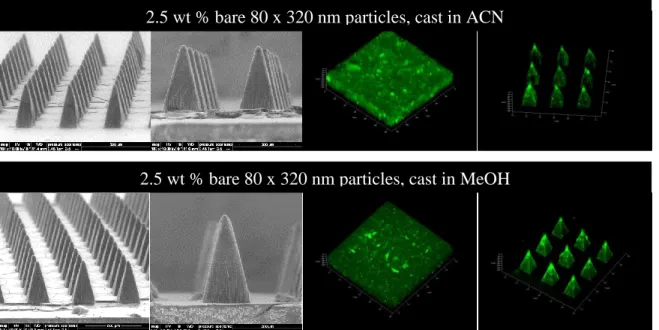
Figure 2.15 Films and microneedles with bare (+) 80 x 320 nm particles incorporated via a variety of solvents at a loading of 10 wt%. (A) H2O,
(B) ACN, (C) EtOH, (D) IPA, (E) MeOH. ... 45 Figure 2.16 ESEM (left) and confocal microscopy (right) images of PVP
microneedles and films loaded with 80 x 320 nm bare hydrogel particles. ... 46 Figure 2.17 Films (above) and microneedles (below) loaded with 5 wt% 80 x
320 nm hydrogel particles. All particles have been (during PRINTing) with 488 maleimide for ex vivo compatibility. (A) Bare (+) particles, (B) PEGylated (neu) particles, (C) Acetylated (-) particles. ... 47 Figure 2.18 1H NMR traces for the starting product and final product show
a complete disappearance of the alcohol at 3.8 ppm (A) and the appearance of methylene at 4.45 ppm and vinyl proteins around 5-5.6 ppm (B). (A) Z-DOL 4000, (B) 4K PFPE-dMA. ... 50 Figure 3.1 OCT images taken after the application of flexible (left) and rigid (right) PVP PRINT microneedle patches. Brackets indicate the different features imaged. (A) Air above the patch, (B) Backing layer (C) Murine skin. Protrusions into the skin are due to microneedle penetration Scale bar is 350 µm.. ... 68 Figure 3.2 Brightfield macroscopic image after testing with microneedle
patch for 10 s. The pattern of the microneedles can be seen on the skin. In the insert, a single piercing is highlighted. Scale bar is 400 µm. ... 71 Figure 3.3 Brightfield macroscopic images of a microneedle array before and
after insertion into ex vivo mouse skin for 10 s. (A) Microneedle array before testing and, (B) Array after testing and removal. Scale bars are 400 µm. ... 71 Figure 3.4 Image of murine skin after the application of a rhodamine-loaded
microneedle patch for 10 min and less than 200 µL of water to dissolve away that patch backing. Image was taken immediately after dispensing water onto the patch. The backing used was loaded with 0.1% fluorescein dye for imaging purposes. Scale bar is 1 cm. ... 72 Figure 3.5 Brightfield macroscopic images of murine skin after fixation.
(A) Control murine skin, not exposed to microneedles. (B) Murine skin after the insertion of rhodamine-loaded microneedles for 10 min. After
xv
Figure 3.6 Brightfield microscopic images of skin sections after sectioning and histology (A) Control skin. (B) Skin after 10 second microneedle
application. (C) Skin after 10 minute microneedle application. Epidermis = top. Scale bar on all images is 35 µm. ... 73 Figure 3.7 Fluorescent microscopy images of skin after sectioning. (A) Control
skin, (B) Skin after 10 second microneedle application, (C) Skin after 10 minute microneedle application. Epidermis = top. Scale bar is 35 µm. ... 74 Figure 3.8 Static Franz diffusion cell apparatus.6 ... 75 Figure 3.9 Release profiles of rhodamine through ex vivo murine tissue over
24 h. It was seen that the microneedles delivered a significantly higher dose than the solution at all given times. ... 77 Figure 3.10 Fluorescent microscopy images, shown as overlays with the brightfield
channel, of skin after the application of a rhodamine drug surrogate for 24 hours on a Franz cell apparatus. (A) Control (no rhodamine applied), (B) rhodamine delivered via pre-microneedle solution, and (C) rhodamine delivered via microneedles. Epidermis = top. Scale bar is 40 µm. ... 78 Figure 3.11 Fluorescent microscopy images, shown as overlays with the brightfield
channel, of skin after the application of pre-microneedle films containing protein drug surrogates[(A) aldolase, (B) OVA]. The fluorescence of the protein, tagged with AlexaFluor 488, cannot be seen in the skin. Epidermis = top. Scale bar is 40 µm. ... 79 Figure 3.12 Release profiles of protein drug surrogates, aldolase and OVA, through
ex vivo murine tissue over 24 h. It was seen that the smaller protein was able to permeate the skin at a much higher efficiency, up to 18% of the loaded dose. ... 81 Figure 3.13 Fluorescent microscopy images, shown as overlays with the brightfield
channel, of skin after the application of microneedles loaded with aldolase (A) and OVA (B) for 24 hours on a Franz cell apparatus. While aldolase is localized below the skin in select regions of the upper dermis, OVA has
penetrated the full thickness of the tissue. Epidermis = top. Scale bar is 40 µm. ... 82 Figure 3.14 Release profiles of bare (+), PEGylated (neu), and acetylated (-)
xvi
Figure 3.15 Fluorescent microscopy images, shown as overlays with the brightfield channel, of skin after the application of microneedles loaded with 80 x 320 nm PRINT particles for 24 hours on a Franz cell apparatus. (A) control, (B) bare particles, (C) PEGylated particles, and (D) acetylated particles. Particles are show to be localized to the site of penetration with all surface charges. Epidermis = top. Scale bar is 40 µm. ... 84 Figure 3.16 Nude mouse with a PRINT microneedle patch applied to the back.
Patch is loaded with 0.1 wt% DyLight 680 cargo. ... 85 Figure 3.17 Mice at three points during the time course small molecule dye
study: (Top) All patches on, (Middle) two patches wiped, and (bottom) all patches wiped. The clean wipe after final water application is highlighted in the middle image. ... 88 Figure 3.18 Organ harvest of a mouse after the conclusion (72 min) of the small
molecule dye study. Fluorescence from the delivered dye can only be seen in the treated skin. ... 89 Figure 3.19 Microscopy images of skin penetration studies performed on ex vivo
human skin from a patient with IBC. (A) Brightfield image of a skin after microneedle insertion for 10 s. (B) Fluorescence image after
microneedle insertion for 10 min. Epidermis = top. Scale bar is 70 µm. ... 90 Figure 3.20 Fluorescent microscopy image, shown as an overlay with the brightfield
channel, of skin after the application of pre-microneedle films containing
particylate drug surrogate (bare 80 x 320 nm particles). The fluorescence of the protein, tagged with AlexaFluor 488, cannot be seen in the skin.
Epidermis = top. Scale bar is 40 µm. ... 96 Figure 4.1 Structure of monomeric human BuChE.8 ... 104 Figure 4.2 PVP microneedles with encapsulated BuChE made from films cast
in water. (A) 5 wt% BuChE, (B) 10 wt% BuChE, (C) 15 wt% BuChE, (D) 20 wt% BuChE, (E) 25 wt% BuChE. Scale bars are 200 µm on all. ... 108 Figure 4.3 Recovered BuChE activity after PRINT processing determined via a
spectrophotometric colinesterase assay (UNC Hematology Core). Pre- and post-processed solid-state films contacting 20 wt% BuChE
recovered over 95% of the BuChE activity charged. ... 109 Figure 4.4 Confocal images of PVP microneedles and films loaded with
fluorescein-tagged BuChE. Representative images of 0.1 wt% (top), 5 wt% (middle), and 25 wt% (bottom) BuChE are shown. With increased BuChE
xvii
Figure 4.5 Confocal microscopy images of microneedles loaded with 20 wt% BuChE tagged with an AlexaFluor 488 probe. ... 111 Figure 4.6 Confocal (top) and ESEM (bottom) images of microneedles made
with 5 wt% BuChE cast in either ACN (left) or EtOH (right)... 112 Figure 4.7 SEM of 1 µm PRINT particles composed of 90% BuChE. ... 114 Figure 4.8 Confocal images of PVP films containing BuChE 1 µm particles.
(A) Non-crosslinked particles, and (B) Crosslinked BuChE 1 µm particles. ... 115
Figure 4.9 ESEM and confocal images of PRINT PVP microneedles incorporating 1 µm BuChE PRINT particles. (top) Non-crosslinked, and (bottom)
Crosslinked particles. ... 115 Figure 4.10 SEM images of crosslinked 1 µm BuChE particles after release from
(A) PVP films and (B) PVP microneedles. ... 117 Figure 4.11 Release profiles of BuChE through ex vivo murine tissue over 24 h.
(A) BuChE alone, and (B) this enzyme in comparison to OVA and aldolase. ... 118 Figure 4.12 Fluorescent microscopy images, shown as overlays with the brightfield
channel, of skin after the application microneedles loaded with free
tetrameric BuChE for 24 hours on a Franz cell apparatus. The enzyme is localized below the skin in select regions of the lower epidermis.
Epidermis = top. Scale bar is 40 µm. ... 119 Figure 5.1 Chest wall presentation of one patient with IBC.9 ... 131 Figure 5.2 Structure of docetaxel. ... 133 Figure 5.3 DSC trace of the 20 wt% docetaxel (in PVP) film, showing only
a glass transition temperature at 38.91 °C. ... 134 Figure 5.4 ESEM images of microneedles loaded with 5 wt% docetaxel. Scale
bars are 100 µm. ... 135 Figure 5.5 Nu/Nu mouse from the microneedle MTD study after four weeks of
xviii
Figure 5.6 Key white blood cell and red blood cell levels as determined from the microneedle MTD study on nude non-tumor bearing mice. Total WBC count, as well as lymphocyte, granulocyte, and monocyte individual levels, did not vary predictably with dose. Total RBC and platelet counts also did not show dose-dependent changes. All parameters were within the normal ranges for nu/nu mice... 141 Figure 5.7 Nu/Nu tumor-bearing mouse (SUM149 model) with a 20 wt% docetaxel
microneedle patch affixed to the skin directly above the tumor mass. Patch application location is outlined with a black circle. ... 143 Figure 5.8 Chromatograms of a representative standard, film, and microneedle
patch are shown. The PVP peak can be seen at 14.3 minutes and the docetaxel peak at 27.0 min all materials analyzed. Chromatograms are displayed as observed in ChemStation (Agilent). ... 147 Figure 6.1 Drawing lithography for microneedle master fabrication, developed
by Lee and Jung.26 (A) The glass transition history of the SU-8 polymer in the cooled-down temperature. (B) After the SU-8 contacted the patterned pillar, drawing lithography was performed. (C) Drawing caused the
appearance of an extended conical-shaped bridge between the plate and pillar in the glass transition. (D) The desired liquid bridge was cured to generate a rigid structure. (E) The separation of the 3D microstructure bridge at the narrow necking position by isolation drawing produced the ultrahigh aspect ratio solid microneedle molds. ... 158 Figure 6.2 Long, medium, and short microneedles to target the dermis, lower
epidermis, and stratum corneum respectively. ... 160 Figure 6.3 Structure of (A) docetaxel, (B) lipidized docetaxel with a C4 alkyl chain,
xix LIST OF TABLES
Table 1.1 Methods of enhancing transdermal delivery ... 5
Table 1.2 Recent advances in biodegradable and water-soluble microneedles ... 13
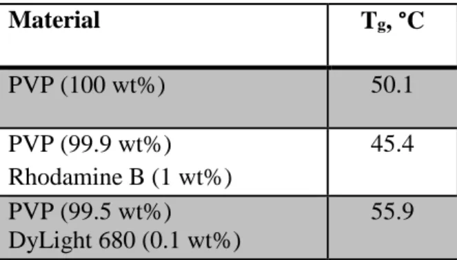
Table 2.1 Glass transition temperatures of films containing drug surrogate cargos ... 34
Table 2.2 Hydrogel particle composition for 80 x 320 nm PRINT particles ... 42
Table 2.3 Particle characterization for 80 x 320 nm PRINT particles ... 43
Table 2.4 Loading efficiency of 80 x 320 nm bare hydrogel particles into PVP microneedles, as compared to the particle wt% charged, 2.5% ... 46
Table 2.5 Glass transition temperatures (Tg) observed via DSC of VA64 substrates loaded with plasticizers and fluorescein dye. ... 52
Table 3.1 Microneedle depth of penetration as determined by OCT. ... 68
Table 3.2 Study parameters for the in vivo release and biodistribution of small molecule drug surrogates ... 87
Table 4.1 Glass transition temperatures of BuChE films cast in acetonitrile, isopropanol, and ethanol ... 112
Table 4.2 Absolute activity of BuChE recovered from films cast in EtOH, IPA, and EtOH ... 113
Table 4.3 Study parameters for the in vivo detection of BuChE in circulation after treatment with microneedles ... 120
Table 4.4 Change in cholinesterase activity after high activity BuChE microneedle administration in vivo, as determined by the UNC Histology Core. ... 121
Table 5.1 Glass transition temperatures (Tg) of the PVP pre-microneedle films loaded with docetaxel. ... 135
Table 5.2 HPLC parameters for the separation and quantification of PVP and docetaxel ... 137
xx
xxi
LIST OF SCHEMES
xxii
LIST OF ABBREVIATIONS AND SYMBOLS ACN acetonitrile
AEM aminomethyl methacrylate APC’s antigen presenting cells BSA bovine serum albumin BuChE butyrylcholinesterase C concentration of drug C0 donor concentration of drug
C4, C8, C18 alkyl chain containing 4, 8, or 18 carbons
CAD computer aided design
cGMP current good manufacturing practices CHTN cooperative human tissue network cm2 centimeters cubed
CMC carboxymethyl cellulose CrOx chromium oxide
D diffusion coefficient DBU diazabicycloundecene DLS dynamic light scattering DMF dimethylformamide DNA deoxyribonucleic acid
DSC differential scanning calorimetry DSS disuccinimidyl suberate
xxiii EDTA ethylenediaminetetraacetic acid EGFR epidermal growth factor receptor ER estrogen receptor
ESEM environmental scanning electron microscopy EtOH ethanol
FDA Food and Drug Administration F-o-A fluorescein-o-acrylate
ft feet
g g force
g grams
GRAS generally regarded as safe
h height
h hours
H&E haematoxylin and eosin
H2O water
HCL hydrochloride
HER-2 hormone epidermal growth factor receptor 2 HP4A hydroxy tetraethylene glycol monoacrylate
HPLC high performance liquid chromatography IACUC Institutional Animal Care and Use Committee IBC inflammatory breast cancer
IPA isopropanol
xxiv
IVIS quantitative fluorescence imaging through Caliper Life Sciences K partition coefficient
kDa kiloDaltons, or 1000 g/mol
l length
LD50 lethal dose fifty percent
LED light emitting diode
MeOH methanol
min minutes
mJ/cm2 milliJoules per centimeters squared
mL milliliters
mm3 millimeters cubed mmol millimoles
mol moles
MRI magnetic resonance imaging MTD maximum tolerated dose
mW megawatts
Mw molecular weight
n number of repetitions
NADH nicotinamide adenine dinucleotide NHS N-hydroxysuccinimide
nm nanometer
xxv OCT optical coherence tomography
OCT optimum cutting temperature medium OVA ovalbumin
PBS phosphate buffered saline PDI polydispersity index PDMS polydimethyl siloxane PEB post-exposure bake PEG polyethylene glycol
PEGylation the result of chemically modifying the surface of a PRINT particle with PEG PET poly(ethylene terephthalate)
PET positron emission tomography PFPE perfluoropolyether
PGMEA propylene glycol monomethyl ether acetate pI isoelectric point
PLGA poly-D,L-lactide-co-glycolide PR progesterone receptor
PRINT Particle Replication In Non-wetting Templates PSI pounds per square inch
PVME/MA poly(methylvinylether-co-maleic anhydride) PVOH polyvinyl alcohol
xxvi
RT room temperature
s seconds
SEM scanning electron microscope STL stereolithography
SU-8 epoxy-based photoresist t1/2 half life
TEC triethyl citrate
Tg glass transition temperature
TGA thermogravometric analysis TMC trimethyl citrate
TPO trimethylbenzoyl diphenylphosphine oxide U units of enzymatic activity
UV ultra-violet
VA64 polyvinylpyrrolidone/polyvinylacetate copolymer
w width
WBC white blood cell
wt% weight %
ZDOL 4000 hydroxy-terminated PFPE with a molecular weight of 4 kDa
Δx, Δy change in the x or y direction ζ-potential zeta potential
% percent
® registered
xxvii
µg microgram
µL microliter
µm micrometer
µmol micromol
1D, 2D, 3D one, two, or three dimensional
1H NMR proton nuclear magnetic resonance
1
CHAPTER 1 MICRONEEDLE TECHNOLOGY FOR THE ADVANCEMENT OF TRANSDERMAL DRUG DELIVERY
1.1 Challenges in Drug Delivery
Every year, research laboratories in corporations and universities aim to create new prescription drugs, over-the-counter medications, cancer treatments, and gene therapy agents, many of which are novel, unique molecules. Before a drug can be implemented in clinics across the country, it must be rigorously tested to assure its safety and effectiveness. Of the thousands of newly developed drugs each year, less than fifty, on average, are fit to apply for approval from the Food and Drug Administration (FDA).1 Each of these represents a unique innovation, the time and manpower of many, and often hundreds of millions of dollars. In recent history, from 2006 to 2010, as few as eighteen (seen in 2007) and as many as twenty-six (seen in 2009, see Figure 1.1) have been approved.1
Figure 1.1 FDA New Molecular Entities (NME) approved from 2006-2010.1
Nu
m
b
e
r
A
p
p
rove
2
However, the delivery route of every new drug, as well as the thousands of existing medications, greatly impacts its effectiveness, influencing dose, biodistribution,
pharmacokinetics, and pharmacodynamics. Many promising new therapeutics are large
biomolecules, such as peptides, proteins, antibodies, and nucleic acids.2 These molecules can be too large, fragile, or insoluble for delivery by traditional routes of introduction.3,4 They may be unable to overcome biological barriers, disassociate before they reach their target, or be difficult to formulate in necessary solvents.2-4 Therefore, large volumes of these drugs are usually
required to be effective, significantly raising costs.3,4 Additionally, highly cytotoxic drugs, such as cancer therapies, can lead to harsh side effects.4 In these cases, lower drug dosages would be preferred for treatment; however, the amount required remains quite high in order to achieve a clinically-relevant therapeutic effect. In spite of the high levels of administered therapeutic, as little as 1% of the dosed therapy reaches solid tumors by standard systemic delivery alone.5
Standard delivery of drugs can be focused in four main categories: oral, inhaled, hypodermic injection, and transdermal application. Oral drugs, commonly pills or liquids, are very familiar to patients and are generally low cost. However, the harsh environment of the gastrointestinal tract and likelihood of first pass metabolism by the liver limit the selection of drugs delivered orally.6 Inhaled therapies allow the localized delivery of medication to the lungs
with minimal side effects, but these generally are more costly than oral formulations.
3
Furthermore, intramuscular injections – common for vaccines – do not deliver doses to the optimum location to elicit an immune response; they penetrate into muscle, a region known to have a lower density of immunologically sensitive cells than skin.3,11-13 Therefore, a large volume of active agent is used, leading to higher cost. Transdermal patches are effective for select time-released drugs (like nicotine and motion sickness medications), but the epidermis (specifically the stratum corneum) limits the diffusion of most drugs through the skin.8-10 Clearly, the ability to transport therapeutics effectively into the body remains a significant challenge.
1.2 Transdermal Drug Delivery
While there are limitations to traditional transdermal drug delivery, which typically relies on the passive diffusion of therapeutics through the skin, this route of administration remains very promising. First, the gastrointestinal tract and first pass metabolism would be avoided by introducing the therapy transdermally.8-10 Drug peak plasma levels are reduced, compared to intravascular delivery, leading to decreased side effects.9 Also, drugs with short biological half-lives or narrow therapeutic windows could be introduced effectively within the skin.9 Finally, by
introducing drugs to the skin, therapeutic exposure at the point of entry would allow for the treatment of local aliments. Due to the structure of the skin itself, systemic exposure through lymphatic drainage via Langerhans or dermal dendritic cells and diffusion into the blood system could be achieved.8
4
barrier of diffusion. Due to the densely-packed, lipophilic cells layered 10-15 μm thick,
molecules larger than 500 Daltons (Da) cannot passively breach this layer.6,8-10,14 Directly below
the stratum corneum is the viable epidermis. While not vascularized, this layer is composed of live skin cells and Langerhans cells, the immune cells of the epidermis. The dermal layer is much more robust than the epidermis, functioning as the connective tissue between the epidermis and subcutaneous fat. The junction between the epidermal and dermal tissue is a complex
glycoprotein structure, forming a 50 nm mechanical support that anchors the two layers.2,16 A
therapeutic must pass through this structure to reach the rich network of capillaries
approximately 200 µm below the skin surface; it has been shown that therapeutic dermal reach is indicative of systemic exposure and absorption.2 In addition, the dermal layer also houses
lymphatics, hair follicles, sweat glands, and is rich in dendritic immunostimulatory cells. Encapsulated nerve endings do reach the upper dermal layer of the skin, but it has been shown that these receptors respond to gentle pressure, not pain.2 Pain receptors are located much deeper in the skin, at the junction of the dermal and subcutaneous layers.
5
The transdermal route, therefore, has become a focus of innovative research in drug delivery after the approval of the first transdermal medication in 1981 (patches for the delivery of the motion sickness drug scopolamine).9 Since then, more than thirty-five transdermal
products have been approved in the US.9 Research labs across the country have been focusing on how to overcome the passive diffusion limit of the skin and widen the scope of medications that can be delivered transdermally.
While many approaches have been published and implemented, transdermal enhancement methods fall into three major categories: formulation-based, electrically-based, and structure-based (Table 1.1). Formulation-structure-based and electrically-structure-based methods are generally described as non-invasive methods of enhancement.10 Adding a chemical permeability enhancer, such as a fatty acid or surfactant, to the drug formulation allows for lipophilic molecules to be carried through the skin by disrupting the bilayer structure of the epidermis.6,10 Even though this method
is non-invasive, the excipients used can irreversibly damage the epidermis and cause high levels of skin irritation.
Table 1.1 Methods of enhancing transdermal delivery
Method Formulation-Based
Electrically-Based
Structure-Based Chemical Enhancers X
Ultrasound X
Iontophoresis X
Electroporation X
Skin Ablation X
Jet Injection X
6
Electrically-based methods increase the permeability of the skin by exposing it to a focused current or energy, but they are generally associated with complex, expensive devices.6
Iontophoresis drives charged or neutral drugs across the skin by applying a small, constant electric potential to a reservoir of drug in contact with the skin. Charged drugs penetrate the skin via electrophoretic mobility, while the electroosmotic flow of water molecules carries in weakly or uncharged drug molecules.6,9 This method can be used to transport molecules up to a few thousand Da through the stratum corneum.6,9 Skin irritation can still occur because iontophoresis
is not localized to this upper epidermal layer. Ultrasound increases the permeability of the skin by applying a pressure wave at a frequency much higher than what is detectible by the human ear.6 This disrupts the lipid structure of the stratum corneum, allowing larger molecules to passively diffuse through the skin (up to a few thousand Da). Again, damage to the lower layers of the skin is possible due to the heat generated from these waves. Finally, electroporation utilizes high voltage pulses to form small, transient pores in the skin. After undergoing electroporation treatment, macromolecule therapies up to 40 kDa have been successfully delivered transdermally.6 While the high electrical resistance of the stratum corneum protects deeper tissue through one treatment, repetitions of the therapy can cause damage to the lower tissue.
7
interrupts the stratum corneum by delivering a liquid or powdered drug with high pressured compressed gas.2,17 A supersonic flow of gas (with a velocity ranging from 100-200 m/s)
penetrates deep into the dermis; when the therapeutic of interest is introduced to the stream, it is deposited into the skin. Such needleless injections have been successful in delivering vaccines and lidocaine, but require expensive equipment and show high variability in dosing accuracy.2 Presently, microneedle devices are considered the most promising, novel structure-based enhancement, demonstrating the successful delivery of small to large therapeutics both locally and systemically; such devices are the focus of this research.
1.3 Microneedles
Microneedles are arrays of micron-sized projections for localized and systemic drug delivery. Considered minimally-invasive, these devices pierce the skin, like hypodermic needles, creating channels for the passage of a therapeutic (see Figure 1.3).8-12,18 However, the small size of the micro-projections (typically 25 – 2000 µm in length) allows them to enter the skin
painlessly, for they only reach encapsulated nerve endings that serve as pressure receptors.2 In
8
may enable inexpensive fabrication and patient self-administration. Therefore, an optimized microneedle device could offer the efficacy of a hypodermic needle with the advantages of transdermal delivery.
Figure 1.3 Transdermal drug delivery via microneedle devices.29
1.3.1 Types of Microneedles
9
a hollow needle array, a pump drives drug from an external reservoir through the skin; the device would be removed after dosing, as shown in Figure 1.4D.
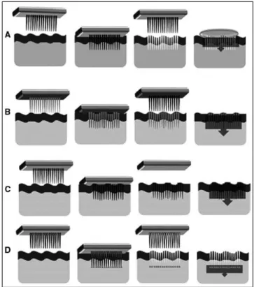
Figure 1.4 Schematics of the application strategies for the four main configurations of microneedle devices. (A) solid and uncoated, (B) solid and coated, (C) biodegradable, (D) hollow.10
To these aims, microneedles have been made from a wide variety of materials in
numerous shapes, sizes, lengths, and configurations.3,10-13,22,31 Predominately, the fabrication of microneedle arrays employs manufacturing techniques common to the microelectronics industry, such as injection molding, isotropic etching, bulk machining, reactive ion etching,
10
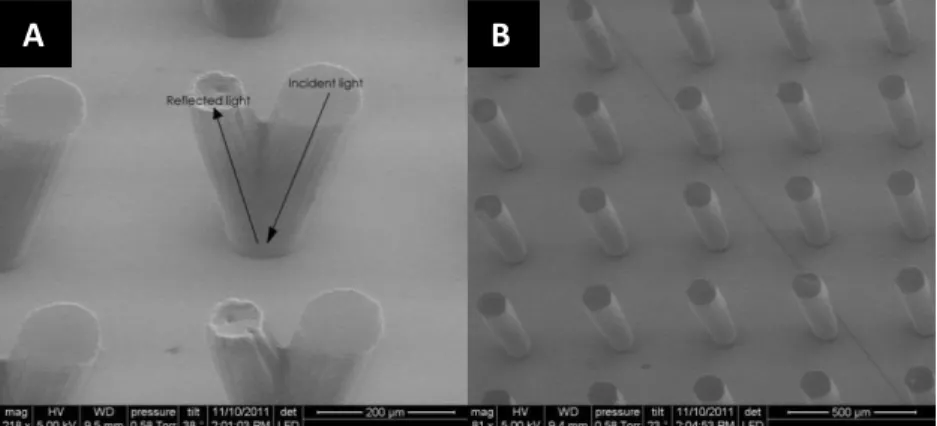
microneedles are fabricated via laser etching in-plane with the backing then bent to be out-of-plane for application, can be seen in Figure 1.5A. Solid silicon microneedles (Figure 1.5B) are commonly made via deep reactive ion etching through a chromium mask.2,11,18 In Figure 1.5C, a silicon wafer, first etched with an array of holes via deep reactive ion etching, was processed to create a microneedle around each hole via subsequent etching, resulting in an array of hollow silicon microneedles orders of magnitude smaller than a hypodermic needle.36 Polymeric
microneedles (carboxymethyl cellulose), made via molding technologies after the fabrication of a master template with traditional photolithography, are shown in Figure 1.5D.
Figure 1.5 Recent advances in microneedle technologies. (A) Metal microneedles made from etched aluminum.18 (B) Solids silicon microneedles.18 (C) Hollow microneedles (500 µm tall) shown next to a hypodermic needle.36 (D) Polymeric microneedles via molding technologies.11
Each microneedle technology is associated with its own advantages and disadvantages. The fabrication techniques for solid metal and silicon microneedles are highly established and reproducible, but they do result in sharp, biohazardous waste after administration and have the
A B
11
potential to fragment in the body, posing immunogenic consequences.2,10 While hollow microneedle arrays allow the most control over dose and reduce payload variability, they also require removal, more sophisticated fabrication, and require pumps that raise the complexity – and cost – of the devices.8,32 Biodegradable and water-soluble microneedle arrays eliminate the sharp, biohazardous waste created with solid and hollow microneedles, eradicating potential immunogenicity concerns and extensive disposal.2,10-13 Due to the promise of biodegradable and water-soluble microneedles, this work focuses exclusively on the development of such devices.
1.3.2 Biodegradable/Water-soluble Microneedles
Biodegradable or water-soluble microneedles have been of great interest to the microneedle community since the early 2000’s, when the limitations of metal and silicon microneedle products were reported by multiple groups.38-40 The biodegradable and
non-biocompatible nature of metal and silicon have been postulated to limit the regulatory
acceptability of such devices by the FDA.2 There is much interest in creating microneedles made out of materials the FDA classifies as Generally Regarded As Safe (GRAS); the reduction in immunoinflammatory response provided by such needles, coupled with their low cost, may lead to an easier path to market.2 Therefore, the ideal microneedle product for market may be a
12
In recent years, this generation of microneedle devices has utilized a number of materials to efficaciously deliver small molecules, biomolecules, and particulate cargo in pre-clinical ex vivo and in vivo studies. For example, the Prausnitz group has pioneered many technologies with polymeric microneedles, such as the polyvinylpyrrolidone (PVP) devices shown in Figure 1.6 for the delivery of red fluorescent bovine serum albumin (BSA).3,6 Another water-soluble polymer, poly(methylvinylether-co-maleic anhydride) (PVME/MA), has been used by Donnelly et al. to mold microneedles for the delivery of theophylline, a hydrophilic drug with a molecular weight of 180 Da.42 The use of other materials – including carboxymethyl cellulose (CMC), poly(lactic-co-glycolic acid), and other constituents – are common for the delivery of small molecules, large proteins, and nanoparticles. Table 1.2 summarizes recent advances in biodegradable and water-soluble microneedles, demonstrating the chemical and pharmaceutical diversity of this promising field. While such devices have shown great promise in animal models – including mice, rats, guinea pigs, and non-human primates – dissolving microneedles have only been translated to human testing with a limited number of technologies.21,39,40,42-44 Hirobe et al. have applied microneedles made from a sodium hyaluronate/dextran/Povidone blend (without therapeutic cargo) to the forearms of the patients to assess dissolution kinetics, skin irritability, pain, and
epidermal water loss; findings concluded that the optimized devices did not cause significant
adverse reactions in any of the test subjects, and the group aims to begin vaccination studies as
Phase I clinical trials.21 MicroCor, a dissolving microneedle patch developed by Corium
International, Inc., has progressed through Phase I safety clinical trials; they began testing these
13
Figure 1.6 Polymer microneedle array manufactured by the Prausnitz group.3,6
Table 1.2 Recent advances in biodegradable and water-soluble microneedles
Material Therapeutic (Cargo)
Therapeutic Size (Small, Medium, Large)
Reference
PVP BSA Medium 3,6
PVME/MA Theophylline Small 42,46
Maltos Nicardiapine HCL Small 40
Human immunoglobulin G Large 44,47
CMC Litocaine HCL Small 48
CMC/PVP Ovalbumin Medium 26
Galactose BSA Medium 39
PLGA BSA Medium 49
Calcein Small 38
CMC nanoparticles Large 50
Dextran Insulin Medium 51
Human growth hormone Medium 52
Interferon-alpha Medium 53
Desmopressin Large 54
Amylopectin Lysozyme Medium 11
Poly(methylvinylether/ maleic acid)
Ibuprofen Small 55
Poly(acrylic acid) PLGA microparticles Large 56
The high ex vivo and in vitro success of biodegradable and water-soluble microneedles, such as those developed by Corium, has led other companies such as 3M, Merck, NanoPass, and TheraJet to set sights to commercialize this technology.2,43,44,57 However, due to the seemingly
14
biodegradable microneedles are currently sold on the market.2,43,44,57 Without the ability to produce a clinically-relevant number of patches that maintain a reproducible size, shape, dose, and configuration, these elegant devices may remain in the lab. By utilizing an inexpensive, fast, reproducible manufacturing technology, biodegradable microneedle devices could be applied to a number of disease models, opening the door for painless vaccines, routine injections, and novel cancer treatments.
1.4 Particle Replication In Non-wetting Templates (PRINT®) Technology
One way to overcome the limitations of current biodegradable microneedle fabrication technologies (discussed in detail in Chapter 2) may be afforded via Particle Replication In Non-wetting Templates (PRINT) technology. The DeSimone Group developed the PRINT technique in the mid-2000’s, leading to the founding of Liquidia Technologies to commercialize the technology.58 PRINT combines lithographic techniques common in the semiconductor industry with flexible, fluorinated molds, allowing for nanomaterials with precisely controlled size, shape, chemical composition, and surface characteristics to be manufactured.4,58-63 The PRINT
process employs a nonwetting, nonswelling mold, made from perfluoropolyether (PFPE); this photocurable polymer has a highly fluorinated surface, which provides a nonwetting interface that allows for organic materials to be removed cleanly. Individual particles on the micro- and nanoscale can be fabricated and isolated using PRINT, adapted easily to a wide variety of matrices.4,58-63 The mild conditions required allow biologic cargo to maintain its function
15
Figure 1.7 Scheme depicting the PRINT process; (1) delivery sheet casting; (2) particle fabrication; (3) particle collection; (4) particle harvesting.4
A brief description of the PRINT process for nanofabrication follows. PRINT begins after the fabrication of a master template, a silicon wafer patterned with the feature size and shape of interest using traditional photolithography techniques. PFPE (mixed with photoinitiator) is then applied to the silicon master template and chemically cross-linked under ultraviolet (UV) light to create an elastomeric mold with cavities of the desired shape and size. The low surface energy of the PFPE allows for it to wet the entire surface of etched silicon wafer, resulting in faithful reproduction of the master template.
16
polyethylene terephthalate (PET), forming a thin film. Residual solvent is removed by heating the thin film, leaving a solid-state film that serves as the delivery sheet for the mold. The uniformity of the thin film allows for particles with controlled size, shape, and chemical composition.
Next, particle fabrication takes place, adhering the delivery sheet (red) to the PFPE mold (green). The PFPE mold is mated to the delivery sheet and passed through a laminator; for matrices that require increased thermal conditions to fill, the laminator is heated. As the sheet (red) leaves the laminator, the mold is then split from the sheet. The cavities in the mold have been filled via capillary action with the particle matrix. The highly fluorinated surface of the PFPE leads to high chemical resistance, preventing the deformation of the PRINT mold when exposed to any residual organic solutions used in pre-particle films and assuring the fidelity of the produced particles to the original master template; no interconnecting or flash layer is observed.58 For thermally cross-linked particles made using the heated laminator, the solution solidifies as the mold cools to room temperature.58
17 1.5 Summary and Hypothesis
Employing the PRINT technique, novel microneedle devices could be made to overcome the manufacturing, cost, and reproducibility limitations of biodegradable and water-soluble microneedles discussed above. After the creation of a master template with the ideal features of a microneedle patch, PRINT can be optimized for a wide variety of matrices, amenable to many cargos due to the mild conditions required. Microneedle devices made from an adapted PRINT platform could be applied to vaccine delivery, preventative medicine, cancers, etc.12,13,64 Herein, we outline the fabrication of PRINT microneedles loaded with small molecules, proteins, and nanoparticle drug surrogates and therapeutics. An investigation of the efficacy of these
18 1.6 References
(1) Food and Drug Administration. How are drugs developed and approved?
http://www.fda.gov/Drugs/DevelopmentApprovalProcess/HowDrugsareDevelopedandAp proved/default.htm (accessed Apr 8, 2012).
(2) Donnelly, R. F.; Singh, T. R. R.; Morrow, D. I. J.; Woolfson, A. D. Microneedle-mediated Transdermal and Intradermal Drug Delivery; John Wiley & Sons, Ltd. 2012. (3) Sullivan, S. P.; Murthy, N.; Prausnitz, M. R. Adv. Mater. 2008, 20, 933-938.
(4) Enlow, E. M.; Luft, C.; Napier, M. E.; DeSimone, J. M. Nano Letters, 2011, 11(2), 808– 813.
(5) Sedlacek, H.; Seemann, G.; Hoffmann, D.; Czech, J.; Lorenz, P.; Kolar, C.; Bosslet, K.
Antibodies as Carriers of Cytotoxicity; Karger. 1992.
(6) Prausnitz, M. R.; Langer, R. Nature Biotechnology, 2008, 26, 1261-1268.
(7) Asthma Attacks Treatment. http://www.asthmatreatmentreport.com (accessed Apr 10, 2012).
(8) Kim, Y.; Prausnitz, M. R. Drug Deliv. and Transl. Res. 2011, 1, 7-12. (9) Kumar, R.; Philip, A. J. Trop.J. Phar. Res. 2007, 6, 633-644.
(10) Escobar-Chávez, J. J.; Bonilla-Martínez, D.; Villegas-González, M. A.; Molina-Trinidad, E.; Casas-Alancaster, N.; Revilla-Vázquez, A. L. J. Clin. Pharmacol. 2011, 51, 964-977. (11) Lee, J. W.; Park, J. H.; Prausnitz, M. R. Biomaterials. 2008, 29, 2113-2124.
(12) Sullivan, S. P.; Koutsonanos, D. G.; Del Pilar Martin, M.; Lee, J. W.; Zarnitsyn, V.; Choi, S.-O.; Murthy, N.; Compans, R. W.; Skountzou, I.; Prausnitz, M. R. Nat. Med.
2010, 16, 915-920.
(13) Lee, J. W.; Choi, S.-O.; Felner, E. I.; Prausnitz, M. R. Small. 2011, 7, 531-539.
(14) The Skin. http://www.technicon.ac.il/~mdcourse/274203.html (accessed Mar 2, 2012). (15) Anatomy of the Skin. http://www.wounds1.com/news/mainstory.cfm/13/1 (accessed Mar
2, 2012).
(16) Claudy, A. L. Annals de Dermatologie et de Venereology. 1986, 113, 1161-1166. (17) Roberts, L. K.; Barr, L. J.; Fuller, D. H.; McMahon, C. W.; Leese, P. T.; Jones, S.
19
(18) Georgia Institute of Technology. Laboratory for Drug Delivery.
http://drugdelivery.chbe.gatech.edu/gallery_microneedles.html (accessed Jan 7, 2015). (19) Neha, A.; Kamaljit, S.; Ajay, B.; Tarun, G. Int. Res. J. Pharmacy. 2012, 3, 102-104. (20) Gill, H. S.; Denson, D. D.; Burris, B. A.; Prausnitz, M. R. Clin. J. Pain. 2008, 24, 585–
594.
(21) Hirobe, S.; Azukizawa, H.; Matsuo, K.; Zhai, Y.; Quan, Y.; Kamiyama, F.; Suzuki, H.; Katayama, I.; Okada, N.; Nakagawa, S. Pharm. Res. 2013, 30, 2264-2674.
(22) Coulman, S. A; Anstey, A.; Gateley, C.; Morrissey, A.; McLoughlin, P.; Allender, C.; Birchall, J. C. International journal of pharmaceutics, 2009, 366, 190-200.
(23) Lee, S. H.; Lee, H. H.; Choi, S. S. Korean J. Chem. Eng. 2011, 28, 1913-1917.
(24) Chandrasekhar S.; Iyer, L. K.; Panchal, J. P.; Topp, E. M.; Cannon, J. B.; Ranade, V. V.
Expert Opin. Drug Deliv. 2013, 10, 1155-1170.
(25) Zaric, M.; Lyubomska, O.; Touzelet, O.; Poux, C.; Al-Zahrani, S.; Fay, F.; Wallace, L.; Terhorst, D.; Malissen, B.; Henri, S.; Power, U. F.; Scott, C. J.; Donnelly, R. F.;
Kissenpfennig, A. ACS Nano. 2013, 7, 2042-2055.
(26) Bediz, B.; Korkmaz, E.; Khilwani, R.; Donahue, C.; Erdos, G.; Falo, L. D.; Ozdoganlar, O. B. Pharm. Res. 2014, 31, 117-135.
(27) Srinivas, P.; Shanthi, C. L.; Sadanandam, M. International Journal of Pharmacy Technology. 2010, 2, 329-344.
(28) Davis, S. P.; Landis, B. J.; Adams, Z. H.; Allen, M. G.; Prausnitz, M. R. Journal of biomechanics, 2004, 37, 1155-63.
(29) BASF. Strategies for skin permeation enhancement. http://www.skin-care-
forum.basf.com/en/articles/skin/strategies-for-skin-penetration-enhancement/2004/08/12?id=5b9a9164-6148-4d66-bd84-6df76bd6d111&mode=Detail (accessed Jan 8, 2015).
(30) Henry, S.; McAllister, D. V.; Allen, M. G.; Prausnitz, M. R. J. Pharm. Sci. 1998, 87, 922-925.
(31) Raphael, A. P.; Prow, T. W.; Crichton, M. L.; Chen, X.; Fernando, G. J. P.; Kendall, M. A. F. Small, 2010, 6, 1785-1793.
20
(33) Ami, Y.; Tachikawa, H.; Takano, N.; Miki, N. J. Micro/Nanolith. 2011, 10, 011503. (34) Li, B.; Liu, M.; Chen, Q. J. Microlith. Microfab. Microsys. 2005, 4, 043008.
(35) Kim, J. L.; Allen, M. G.; Yoon, Y. K. J. Microcech. Microeng. 2011, 21, 035003. (36) McAllister, D. V.; Wang, P. M.; Davis, S. P.; Park, J. H.; Canatella, P. J.; Allen, M. G.;
Prausnitz, M. R. Proc. Natl. Acad. Sci. U S A. 2003,100, 13755–13760. (37) Prausnitz, M. R. Adv. Drug. Deliver. Rev. 2004, 56, 581-587.
(38) Park, J. H.; Allen, M. G.; Prausnitz, M. R. Pharm. Res. 2006, 23, 1008-1019. (39) Donnelly, R. F.; Morrow, D. I. J.; Thakur, R. R. S.; Migalska, K.; McCarron, P. A.;
O’Malley, C.; Woolfson, A. D. Drug Dev. Ind. Pharm. 2009, 35, 1242-1254. (40) Miyano, T.; Tobinaga, Y.; Takahiro, K.; Matsuzaki, Y.; Hitoshi, T.; Makoto, W.;
Katsumi, H. System. Biomed. Microdevices. 2005, 7, 185-188.
(41) Choi, J. W.; Kwon, S. H.; Huh, C. H.; Park, K. C.; Youn, S. W. Skin Res. Tech. 2013, 19, 349-355.
(42) Donnelly, R. F.; Garland, M. J.; Morrow, D. I. J.; Migalska, K.; Thakur, R. R. S.; Majitjiya, R.; Woolfson, A. D. J. Control. Release. 2010, 147, 333-341.
(43) Schoellhammer, C. M.; Blankschtein, D.; Langer, R. Expert Opin. Drug Deliv. 2014, 11, 393-407.
(44) Bariya, S. H.; Gohel, M. C.; Mehta, T. A.; Sharma, O. P. J Pharm. Pharmacol. 2012, 64, 11-29.
(45) Corium. Technology. http://www.coriumgroup.com/Tech_MicroCor.html (accessed Jan 12, 2015).
(46) Donnelly, R. F.; Majitjiya, R.; Singh, T. R.; Morrow, D. I.; Garland, M. J.; Demir, Y. K.; Migalska, K.; Ryan, E.; Gillen, D.; Scott, C. J.; Woolfson, A. D. Pharm. Res. 2011, 28, 41-57.
(47) Li, G.; Badkar, A.; Kalluri, H.; Banga, A. J. Pharm. Sci. 2010, 99. 1931-1941. (48) Vajragupta, O.; La-Ong, S. Drug Dev. Ind. Pharm. 1994, 20, 2671-2684.
21
(50) Jae-Ho, O.; Park, H. H.; Ki-Young, D. O.; Han, M.; Hyun, D. H.; Kim, C. G.; Kim, C. H.; Lee, S. S.; Sung-Joo, H.; Shin, S. C.; Cho, C. W. Eur. H. Pharm. Biopharm. 2008, 69, 1040-1045.
(51) Ito, Y. H.; Eiji, H.; Atsushi, S.; Nobuyuki, S.; Kanji, T. Eur. J. Pharm. Sci. 2006, 29, 82-88.
(52) Ito, Y.; Ohashi, Y.; Shiroyama, K.; Sugioka, N.; Takada, K. Biol. Pharm. Bull. 2008, 31, 1631-1633.
(53) Ito, Y.; Saeki, A.; Shiroyama, K.; Sugioka, N.; Takada, K. J. Drug. Target. 2008, 16, 243-249.
(54) Fukushima, K.; Ise, A.; Morita, H.; Hasegawa, R.; Ito, Y.; Sugioka, N.; Takada, K.
Pharm. Res. 2011, 28, 7-21.
(55) McCrudden, M. T. C.; Alkilani, A. Z.; McCrudden, C. M.; McAlister, E.; McCarthy, H. O.; Woolfson, A. D.; Donnelly, R. F. J. Control. Release. 2014, 180, 71-80.
(56) DeMuth, P. C.; Garcia-Beltran, W. F.; Ai-Ling, M. L.; Hammond, P. T.; Irvine, D. J.
Adv. Funct. Mater. 2013, 23, 161-172.
(57) Vaxxas. http://www.vaxxas.com/nanopatch-technology (accessed Jan 18, 2015).
(58) Rolland, J. P.; Maynor, B. W.; Euliss, L. E.; Exner, A. E.; Denison, G. M.; DeSimone, J. M. J. Am. Chem. Soc. 2005, 127, 10096-10100.
(59) Merkel, T. J.; Jones, S. J.; Herlihy, K. P.; Kersey, F. R.; Shields, A. R.; Napier, M. E.; Luft, J. C.; Wu, H.; Zamboni, W. C.; Wang, A. W.; Bear, J. E.; DeSimone, J. M. Proc. Natl. Acad. Sci. U. S. A. 2011, 108, 586-591.
(60) Canelas, D. A.; Herlihy, K. P.; DeSimone, J. M. Wiley Interdiscip. Rev. Nanomed. Nanobiotechnol. 2009, 1, 391-404.
(61) Herlihy, K. P.; Nunes, J.; DeSimone, J. M.; Langmuir. 2008, 24, 8421-8426.
(62) Perry, J. L.; Reuter, K. G.; Kai, M. P.; Herlihy, K. P.; Jones, S. W.; Luft, J. C.; Napier, M.; Bear, J.E.; DeSimone, J. M. Nano Lett. 2012, 12, 5304-5310.
(63) Gratton, S. E. A; Ropp, P. A; Pohlhaus, P. D.; Luft, J. C.; Madden, V. J.; Napier, M. E.; DeSimone, J. M. Proc. Natl. Acad. Sci. U. S. A. 2008, 105, 11613–11618.
22
CHAPTER 2 FABRICATION AND CHARACTERIZATION OF PRINT MICRONEEDLE PATCHES
2.1 Introduction
In assessing the limitations of water-soluble or biodegradable microneedles across the field, it is apparent that many devices are manufactured in a way that fundamentally restricts the advancement of the field as a whole. Traditionally, biodegradable microneedles are made by filling a mold with a matrix containing the drug of interest; generally, multiple vacuum and centrifugation steps are required to completely fill the molds, arduous steps that lead to lengthy fabrication times and pose issues to scale-up manufacturing.1-5 A thick substrate, or backing layer, is attached to the array of microneedles to form a patch. After preparing microneedle patches, they generally are administered as shown in Figure 2.1A. Conventionally, the
microneedle patch is applied topically to pierce the skin and penetrate into the viable epidermis or dermis, depending on the physical dimensions of the needles. Due to skin’s elastic qualities, the entirety of the needle does not enter the skin.6 The needles are left in the skin for the duration of the treatment period, from minutes (min) to hours (h), and the substrate is then removed, extracting all parts of the needle that have not yet dissolved (usually 5-20% of each
23
Figure 2.1 Schematics of the applications of traditional biodegradable microneedles made using PRINT. (A) The needles and substrate (red) are inserted into the skin (top layer = epidermis, middle layer = dermis, bottom layer = subcutaneous fat). The backing is then removed. (B) The needles (red) and substrate (yellow) are inserted into the skin. The backing is then dissolved with tap water.
To overcome the barriers in fabrication of microneedles seen previously, we have created microneedle arrays using Particle Replication In Non-wetting Templates (PRINT®) technology, as described in Chapter 1.7 In summary, this technique combines a “top-down” method of soft
lithography with traditional polymerization to create reproducible features on the nano- and micro-scale with precise control of size, shape, and chemical composition.7-14 A wide range of materials, including biodegradable and water-soluble polymers, sugars, and pure drug could be used, and the mild conditions required allow biologic cargo to maintain its function throughout the process. While the process was first utilized for the fabrication of nano- and microparticles less than 8 µm, the process is amenable to the creation of much larger microstructures (300-400 µm in height) after the fabrication of masters in this size range via traditional photlithography.7-14
PRINT allows for arrays to be made very quickly; after the desired mold is created, it can be used to make a microneedle patch in less than 5 min for batch processes. It can be adapted on
24
any scale of production; this particular advantage will allow for patches of virtually any size to be made affordably and quickly.15
A schematic of a microneedle device made using PRINT can be seen in Figure 2.1B. Through this process, an array of discrete microneedles would be manufactured and collected on a flexible, water-soluble substrate. Traditional microneedle arrays are often subject to the “bed of nails” effect, in which the force on each needle is distributed across the array, resulting in the inability of all needles to overcome the elasticity of the epidermis and pierce the skin.6 The flexibility of the substrate allows the array of highly-dense microprojections to avoid this effect and break the stratum corneum more efficiently.6 After application, the needle patch remains in the skin long enough to allow the polymer to dissolve or degrade, releasing its drug cargo. The substrate would then be dissolved, leaving the entire microneedle array in the skin. In this configuration, the entire payload of drug in the patch would be delivered. While this has been suggested, to our knowledge, no such patches have been created to date. Herein, we demonstrate the fabrication of 100% water-soluble microneedles on flexible substrates and their ability to load drug surrogates of nearly any size, shape, and surface charge while maintaining the function of the cargo after manufacturing.
2.2 Results and Discussion
25
26
Figure 2.2 ESEM images of SU-8 Master template (A & B), PDMS template (C & D) and PFPE mold (E & F) and PVP microneedles (G & H) made from R2 SU-8 master (200 µm squares, 200 µm spacing). Needles show
comparable lengths and tip radii. Scale bars on A, C, E, and G are 500 µm. Scale bars for B, D, F, and H are 200 µm.
2.2.1 Master Template Fabrication
Master templates were first prepared using a tilted-rotated photolithography approach adapted from Han et al.16,18,19 Briefly, a polished silicon wafer was coated with an anti-reflective layer; it was seen that this layer significantly reduced backside reflections and greatly increased the resolution of the resulting master templates (Figure 2.3). A thick layer of negative photoresist
Ne
edl
es
R
epl
ic
a
M
old
M
as
ter
A B
C D
F
G H
27
(SU-8) was applied to the wafer via spin coating. Next, a mask with 200 µm x 200 µm squares and 200 µm spacing (base to base) was placed over the SU-8, and the complex was exposed to ultra-violet (UV) light at incidence angles of 18-25° (Figure 2.4). Both the mask dimensions and the incident angle of UV light determine the depth of the mold, and ultimately, the length of the microneedles.16,17 The wafer was then rotated 90° about the surface normal and exposed again; a total of four exposures led to female master templates with square-pyramidal cavities. These templates were imaged via ESEM to determine the length and tip radii of curvature that would be achieved through replication. Seen in Figure 2.2A-B, the template used for this study was 360 µm in length and had tip radii of curvature under 10 µm. This length was selected based on the desire to reach the viable epidermis after piercing the stratum corneum.
Figure 2.3 Effect of the anti-reflection chrome layer on a silicon wafer after UV exposure. (A)ESEM image confirming the occurrence of backside reflections without the presence of an anti-reflection coating. (B)ESEM image showing the absence of these reflections by adding the anti-reflection coating.
Figure 2.4 Inclined, rotated photolithography schematic for making microneedle master templates. An SU-8 coated wafer is placed on a tilted stage (18-25°) and exposed. The substrate was then rotated 90° about the surface normal and exposed once more. After a total of four exposures, the wafer is post-exposure baked (PEB) and developed, leaving a negative master template.