Wind and Solar Hybrid Generation at
Variable Speed of Wind Based With SOFC
Ms.Komal P.Hole1, Prof.Saurabh H.Thakare2
M.E Scholar, Dept. of Electrical (Electronics & Power)Engg, VBKCOE Malkapur, Maharashtra, India1
Asst. Professor, Dept. of Electrical (Electronics & Power)Engg, VBKCOE Malkapur, Maharashtra, India2
ABSTRACT: This Paper deals with the hybrid system which is depends on the renewable energy sources . The all components used in the hybrid system is easily available in the environment so we used this components for the hybrid system based on SOFC to control the wind energy conversion at the variable speed so we got the reliable . The system consist of the components like Grid , fuel cell , Wind farm , solar panel respectively . In recent time large of industriliazation and other development is occurs so , we needs the power in large scale. In developing countries the advanced new techniques are implemented so that lots of research is get done for making the environment with services . Fuel cell technology is a moderately new energy-storing technology that has the potential to participate with the conventional present generation facilities. Among the various Distributed Generation or onsite generation or localized generation technologies available, fuel cells are being deliberated or considered as a potential source of electricity because they have no geographic boundaries and can be placed any where on a distribution system. Modeling of SOFC is done by using Nernst equation. In that the output power of the fuel cell can be organized by adjusting the flow rate of the fuels used in the procedure and development. The wind energy conversion system (WECS) is equipped with a DFIG and two back-to-back Pulse Width Modulated (PWM) Insulated Gate Bipolar Transistors (IGBTs) based voltage source converters (VSCs) in the rotor circuit. The three phase PWM inverter to get the suitable form three phase output voltages for the grid associated applications. In this paper, design and modeling of Solid Oxide Fuel cell (SOFC), PV Modelling with wind farm is discussed for the distributed generation applications. Modeling and simulations are carried out in MATLAB Simulink platform.
KEYWORDS:Doubly-Fed Induction Generator (DFIG), Wind Energy Conversion System (WECS), RSC (Rotor side controller), GSC (Grid side converter), SOFC (Solid Oxide Fuel Cell system) , PV ( Photo voltaic)
.
I.INTRODUCTION
The growing industrialization and domestics, power demand is increasing vastly. To keep the green environment we have to create power from the various renewable energy sources in environment friendly manner. In present the bulk ac power transmission are not economic and also complex to control the power flow. To stunned this problems wind turbine and photovoltaic generators are used. The proposed hybrid model is most suitable for all weather conditions. And also, it is very safe working atmosphere with the hybrid model. Wind and solar energy is unsteady and unpredictable, and harnessed in relatively small quantities spread over a large area. If it is not properly controlled, the power output of a wind farm and PV array could too small percentage only. In this paper permanent magnet synchronous generator is used with variable speed control employed .
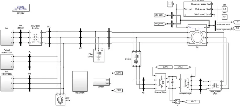
Fig 1:- Simulation of Grid for hybrid system
II. OPERATING PRINCIPLE
The stator is directly joined to the AC mains, that the wound rotor is fed from the Power Electronics Converter via slip rings to allow DFIG to control at a variation of speeds in response to fluctuating wind speed. The frequency of the grid voltage is always kept constant regardless of the wind speed (and thus the rotor speed), by the back-to-back converters. At sub-synchronous speeds the stator is producing the power but part of it has to be fed back to rotor. At super synchronous speeds both the rotor and stator are generating power to the grid. The slip power can flow in both directions, i.e. to the rotor from the supply and from supply to the rotor and hence the speed of the machine can be organized or controlled from either rotor- or stator-side converter in both super and sub-synchronous speed ranges. As a result, the machine can be controlled as a generator or a motor in both super and sub-synchronous operating modes recognizing four operating modes . the structure and the operational of a fuel cell are similar to that of a battery except that the fuel can be continuously fed into the cell .
Fig 2 :- Simulink Model Fuel cell with wind farm( Hybrid system)
fuel cell is used for to stored the power and also for the production of electrical energy. Then power from each component is given by
Load Power requirement = 4 MW
Parameters Power delivered to load (MW) Total Power from the
Parameters
Grid 0.5
3.5 MW
Wind Farm 2
Fuel Cell 0.5
PV-array 0.5
Table 1:- Power delivered from the Sources
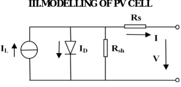
III.MODELLING OF PV CELL
Fig.3:- Equivalent Circuit of PV Module
Normally, voltage output is based on solar irradiation and temperature of the cells. The converter is to get the voltage for which the peak value of power attained or gain from PV cell. The output variable is an increment value which increases or decreases the voltage reference of the PV array. Then the PWM duty cycle of the boost converter connected to the DC-link.
III.SIMULATION RESULT
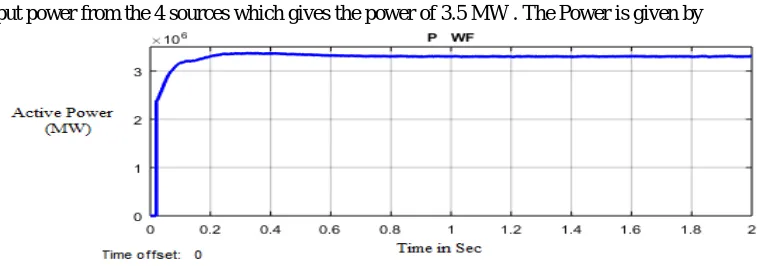
The develop system is carried out in the MATLAB software, The result is gives the result from its respective sources such as wind farm,fuel cell, and PV-array we need the constant power from the sources so that we need the reliable and constant nature output is given by
The power delivered form the wind farm is 2 MW we use the PV-array to provide the continuous power to the load. Then again we use the fuel cell thses fuel cell is utilized for creation of the electrical power and also used to stored the amount of enegy in it. The fuel cell having duel nature,the power delivered from the fuel cell is 0.5 MW. The power of graph is given by
Fig 5:-Real Power delivered from the Fuel Cell
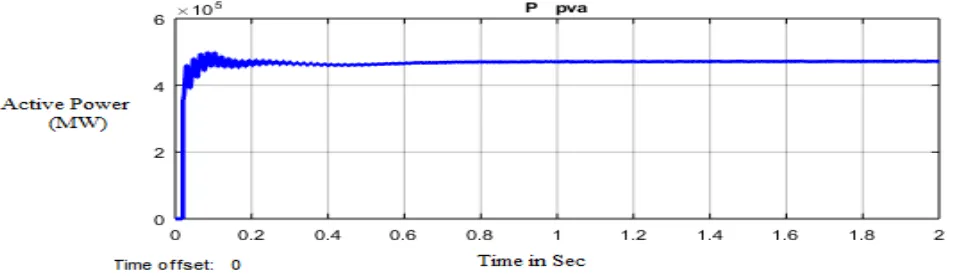
In that we provide the PV-array these PV module is used to delivered the result which is beneficial for our load demand our creation is improve and increase our output .The power delivered from the PV module is 0.5 MW and some power is from the grid is 0.5 MW, The PV -array contains the photo diode which convert the solar energy in to the electrical energy the power from the PV-array is
Fig 6:-Real power Provided from the PV-array
Fig 7 :-Power collection at PCC
The all parameters provide the combine power which are provided to the load then the these power is about the 4 MW it is the output power from the 4 sources which gives the power of 3.5 MW . The Power is given by
Fig 8. -Ovearall output power to the load
IV.CONCLUSION
The simple , easy and most well-organized integrated windmill & Solar with DIFG and PV solar cell system are proposed with SOFC . The advantages of SOFC having strength and the easy to implement when compared to the other fuel cell & it is economically useful & pollution free . It also simplifies to estimate the wind mill structures simply and correctly. Also, this hybrid generation system takes a dissimilar quality that the wind-PV power naturally accompaniment to one another to positive amount, there by assisting constant output power for full day to the load. In future the fuel cell also taken in to the account to achieve not only the constant supply but also better battery life. The system with wind conversion is achieved by vector control at the grid side. So this got the positive response to the power generation.
REFERENCES
[1] Ritika Verma, Prof Amol Barve “Control of Wind Energy Conversion System with SOFC Based Fuel Cell at Variable Speed” Volume 3, Issue 1, January 2013.
[2] J. PULLA RAO, SHAHIMA SHERIEN “Control Scheme for a Stand-Alone Wind Energy Conversion System with Fuel Cell”
Vol.08,Issue.02, February-2016.
[3] Hassan Moghbelli “a Green Hybrid Power Plant Using Photovoltaic And Wind Energy With Power Quality Improvement In Qatar”,
June-2011.
[5] ,RupeshS.Patil , Ashok Kumar Jhala [4] has presented on “Review of Grid Integration of Hybrid Generation” Volume 6 Issue No. 12 , In December 2016 .
[6] R. Jagatheesan, K. Manikandan “An Efficient Variable Speed Stand Alone Wind Energy Conversion System & Efficient Control
Techniques For Variable Wind Applications” Vol. 5, Issue 1, Nov. 2012 .
[7] Devender Sharma , Sushil Kumar , Shiba Arora “Modelling and Simulation of Solid Oxide Fuel Cell for Distributed Generation Using
Simulink” Volume 3 Issue VI, June 2015 .
[8] B.Rohithkumar , N.Narasimhulu “ Operation and Control of Wind/Fuel Cell BasedHybrid Microgrid in Grid Connected Mode” Volume:
02 Issue 08 ,Nov-2015.
[9] Manaullah, Arvind Kumar Sharma , Jamia Milia Islamia,“Performance Comparison of DFIG and SCIG based Wind Energy Conversion
Systems” November 2014.
[10] S. Masoud Barakati “Maximum Power Tracking Control for a Wind Turbine System Including a Matrix Converter” September 2009 .
[11] Said Chikha1 , Kamel Barra “Predictive Control of Variable Speed Wind Energy Conversion System with Multi Objective Criterions”
March 2016 .
[12] RabinarayanaParida , Bibhu Prasad Nanda , Jibanananda Mishra “Sensorless Vector Control of Induction Generators for Variable-Speed
Wind Turbines Using Micro-2407” December 2011.
[13] K. Anand , D. Subramanyam , A. Venkat Rao “Control of Wind Energy Conversion System with Fuel Cell” Vol.04 , Issue.25 , July-2015 .
[14] Y.Madi , Y.Mokhtari , N.Bouali , Pr. T.Rekioua “Study and Control of a Variable Speed Wind Turbine with a Permanent Magnet
Synchronous Generator ” Volume 12 , Jun 2014.