Technology, Sodepur, Kolkata, West Bengal, India1
Student, Department of Applied Electronics and Instrumentation Engineering, Guru Nanak Institute of Technology, Sodepur, Kolkata, West Bengal, India2
ABSTRACT: The daily increasing demand of electricity in modern life leads to abundant usage of electric resources. The household electric loads like electric fans, lights which are commonly used for almost 24 hours in a day often consume extra amount of power as people forget to switch off them even they go out of the room. An automatic switching-off of electrical loads has been proposed in this paper by counting the number of visitors in the room in order to avoid excess consumption of electrical power. The electrical loads will be switched off by use of a digital counter which will continuously monitor the incoming and outgoing of visitors and disconnects the circuit when visitor count becomes zero.
KEYWORDS:IR transceiver, Digital Counter, Electromagnetic Relay, D-Latch.
I.INTRODUCTION
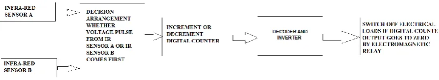
Electricity becomes an integral part of our modern life and the consumption of electric power in each domestic purpose is getting increased day by day. The household loads like lights, fans are used in every house these days. The unawareness of people to switch off these loads leads to unwanted power consumption. In this paper, a suitable technique is proposed in order to automatically switch off the household loads after all the persons go out of the room. A pair of infra-red transmitter and receiver arrangement is installed at the door in order to monitor any incoming and outgoing of people. These IR sensors will enable us to count the total number of persons in the room. The visitor counting is implemented by a digital counter. The counter output is fed to an active low output decoder and an inverter to get high output. An electromagnetic relay circuit (with proper current amplification at the input) will switch off the corresponding load after the counter output goes to zero. The block diagram of the work is shown in Fig 1.
Fig. 1 Block Diagram of automatic switching off of electrical loads
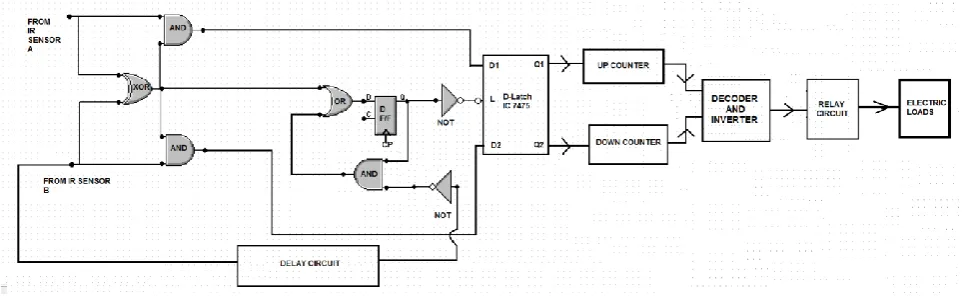
Fig. 2 Detailed Block Diagram and working principle of automatic switching off of household electrical loads
The decision of whether a people is entering or exiting in the room will be determined by a pair of IR-transceivers. The first IR transceiver (IR A) will be mounted close to the door and the second IR transceiver (IR B) will be situated inside the room, slightly distant from the door. The transmitter and receiver segment of a particular IR transceiver will be situated on the two sides of the wall so that whenever a person goes through the door, the IR signal from transmitter will be prevented to reach to the receiver by the people. If a person is coming in the room, he or she will produce obstacle to the ray path of IR A signal which is destined to the receiver before he or she produce obstacle to the ray path of IR B. On the contrary, if a person is going out of the room, he or she will prevent IR B signal before than IR A. Thus the sequence of prevention incidents of two IR transceiver pair will determine whether the person is coming in or going out of the room. This decision will enable the counter to act as either an up counter or a down counter. For an incoming person, IR A voltage pulse will come first and it will enable the counter as up counter. The IR A pulse will also latch the D-Latch inputs. The subsequent IR B voltage pulse which will appear after some seconds will be blocked by the latched D-Latch arrangement and hence IR B input cannot affect the counter. D-Latch is implemented by IC 7475. Likewise, then the person is exiting from the room, IR B voltage pulse will come first and decrement the counter. The IR A voltage pulse, which will come after some seconds will be blocked by D-Latch arrangement. The counter output through an active low output decoder and inverter will drive an electromagnetic relay which is connected to the load. The energizing current of electromagnetic relay is amplified through a current amplification circuit by transistor. Whenever counter output goes to zero, electromagnetic relay circuit will switch off the corresponding circuit.
II.BRIEF EXPLANATION OF COMPLETE CIRCUIT
The brief explanation of working procedure of the decision logic of which IR input comes first is explained in this section with the help of circuit diagram shown in Fig 3.
propagation delay. In this process, counter will be incremented or decremented only by once for entrance or exit of a single person. After a person completes entrance or exit, a pulse from IR sensor B will come through a delay circuit and cause the D flip-flop output to go low. The subsequent inverter output will then go high and this will make the D-Latch IC transparent and new inputs can now affect the Latch IC again and so can increment or decrement the counter again. The delay circuit is implemented by necessary addition of D flip-flops. The same binary counter (from IC 74HC193) is used as up or down counter. The counter output is fed to an active low output decoder. Whenever the counter output goes to zero, the D0 output of decoder generates low output which is inverted by the subsequent inverter to generate a
high output. Due to that high output, the electromagnetic relay will get excited and it will break the electric load connection from the power supply. Hence it will be possible to switch off the load after the number of people in a single room becomes zero. This circuit can also be used to turn on the loads again if a person enters again into the room.
III.INITIAL DEVELOPMENT OF THE CIRCUIT
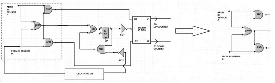
In stage 1, the portion of the circuit from decision logic segment which has been already implemented is shown in Fig 4. The circuit (shown at the left side of Fig 4) enclosed in dashed region is completely implemented and tested (shown at the right side of Fig 4).
Fig. 4 In stage 1, the portion of circuit diagram which has been implemented
Fig. 5 The replacement of D flip-flop by JK flip-flop
In stage 2, the circuit has been developed slightly further and the portion of circuit which has been developed till now is shown in Fig 6.
Fig. 6 In stage 2, the portion of circuit diagram which has been implemented
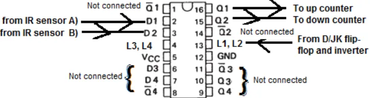
IV.D-LATCH CIRCUIT CONNECTIONS
The IC 7475 is a four bit bistable D-Latch IC with Latch inputs. If Latch input goes to low, the output for corresponding flip-flops are latched and they retain the previous value. Inputs can affect the D flip-flops only when the Latch inputs are high (Transparent state). In the proposed circuit, all the Latch inputs are tied in order to make all the D flip-flops latched or transparent simultaneously. Only two D-Latch is used for up counting and down counting procedure (D1-Q1 and D2-Q2). The latching is done to ensure only a single transition of digital counter for entire entrance or exit period of a person. The necessary circuit connections are shown in Fig 7.
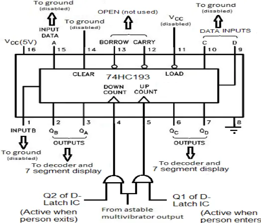
Fig. 8 The circuit connections for 74HC193 counter
VI.DECODER AND RELAY CONNECTIONS
The outputs of counter is fed to a 4x16 active low decoder (74LS154) to generate the necessary combinations as well as to LED to indicate the total number of persons currently staying inside the room. From eight active low outputs of decoder (D0 –D7), D0 is connected to an inverter and then fed to the electromagnetic relay. A single pole double throw
(SPDT) relay is used for this purpose. The ‘common’ terminal of the relay is switched from ‘Normally Connected (NC)’ terminal to ‘Normally Open (NO)’ whenever the relay gets excited. The excitation comes from the inverted D0 output of
decoder. The loads are disconnected from the power source when NC gets disconnected from common terminal. A current amplification is done by an npn transistor BC547 in order to provide necessary excitation current to electromagnetic relay. The block diagram from counter output to relay is shown in Fig 9.
Fig. 9 Block diagram for the connection from Digital counter to Electromagnetic Relay
Fig. 10 Some snapshots of different phases of circuit development
VII. CONCLUSION
The cheap solution for the excessive power wastage proposed in this paper can be easily implementable to the home power supply system. The advantages are summarized here at conclusion.
1. This system reduces human workload.
2. This circuit is very useful to save excessive wastage of electricity. 3. This circuit is very cheap and very easy to implement.
4. This circuit can also be used to switch-on the loads (light/fan) whenever a person gets into the room again.
REFERENCES
[1] http:// www.datasheetcatalog.com. [2] http:// www.alldatasheet. com.
[3] http:// multimedia-logic.software.informer.com/1.4/. [4] http:// www.allaboutcircuits.com/vol_4/chpt_11/5.html. [5] Texas Instruments website.
[6] Electronics: Fundamentals and Applications, by D. Chattopadhyay, P.C. Rakshit. [7] Digital Circuits and Design by S Salivahanan & S Arivazhagan.
[8] Electronics For You.