Inverse Kinematic Analysis of Lab-Volt R5150 Robot system
Dr.Tahseen Fadhel Abaas*, Hind Hadi Abdulridha**
Production Eng. & Metallurgy Department, University of Technology, Iraq * Email: [email protected]
** Email: [email protected]
ABSTRACT
Kinematics analysis is the conversion from the Cartesian space to the joint space and vice versa. In this paper, an inverse kinematics modeling of 5 DOF stationary articulated robot arm which is used for educational tasks are presented, and shows an adopted modeling method to simulate and represent the simultaneous positional coordinates for each joint of the robot while it moving from one target to another. The standard Denavit-Hartenberg (DH) model is applied to build the mathematical modeling to determine and simulate the position and orientation of the end effector of (5 DOF) Lab-Volt R5150 robot manipulator. The simulation of the inverse kinematic of the robot arm is done through MATLAB software and compare the results with the data from RoboCIM software to know that the model is suitable for simulate and represent.
Keywords - Lab-Volt R5150 robot arm, D-H parameters, DOF, Inverse Kinematics.
1. INTRODUCTION
The inverse kinematics solution, it is essential for robots that follow paths. A computer control system called the controller, commands the robot to move through its workspace based on a plan or desired trajectory of the robot end- effector. The plan is developed using an inverse kinematics algorithm which computes the next desired joint configuration given the current configuration and the next desired end effector position [1].
Inverse kinematics deals with the problem of finding the required joint angles to produce a certain desired position and orientation of the end-effector. The inverse kinematics problem is much more complex than direct kinematics, because the kinematic equations are nonlinear, their
solution is not always easy (or even possible) in a closed form. Also, questions about the existence of a solution and about multiple solutions arise [2] [3].
space. This is more difficult problem than forward kinematics [4].
2. Description of Lab-Volt R5150
Robot Arm
For this study, Lab-volt R5150 robot manipulator was selected in this research, as shown in figure (1). It is an educational robot from the family of Lab Volt Automation. It is a small table top robotic arm manufactured by Lab-Volt Inc. It is a 5 DOF manipulator driven by five stepper motors and has a griper as an end-effector, and its motion are controlled by RoboCIM, IM Software [5][6].
Fig 1: Lab-Volt R5150 manipulator
3. Kinematic Analysis of Lab-Volt R5150 Robotic Arm
3.1 Forward Kinematic
In the forward kinematics, the inputs are the joint angles and the link length parameters, while the output of the problem is the position and the orientation of the tool or gripper. The block diagram representation of the direct kinematics shown by Figure (3).
Fig 3: Direct Kinematic Block Diagram.
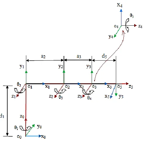
Many methods can be used in the forward kinematics estimation. One of the most used methods is the Denavit-Hartenberg (D-H) analysis, in this method the forward kinematics is calculated from some parameters that have to be defined to produce homogeneous transformation matrix [1]. This matrix specified the position and orientation of the robot arm with respect to the robot base. In Denavit-Hartenberg (DH) convention, each homogeneous transformation is represented as a product of four “basic” transformations:
… (1)
The D-H parameters from Table (1) will be substituted at equation (1). The individual transformation matrices A1 to A5 and the global matrix of transformation A50, can be calculated as follow:
Table 1: D-H parameters for Lab-Volt 5150 arm αi (degree)
ai (m)
di (m)
A10 , A21 , A32 , A43
A54
A50 ……. (2)
3.2 Inverse kinematic
Inverse kinematics deals with the problem of finding the required joint angles to produce a certain desired position and orientation of the end-effector in Cartesian space. Its solution, however, is much more complex than direct kinematics since there is no unique analytical solution.
Each manipulator needs a particular method considering the system structure and restrictions [7].
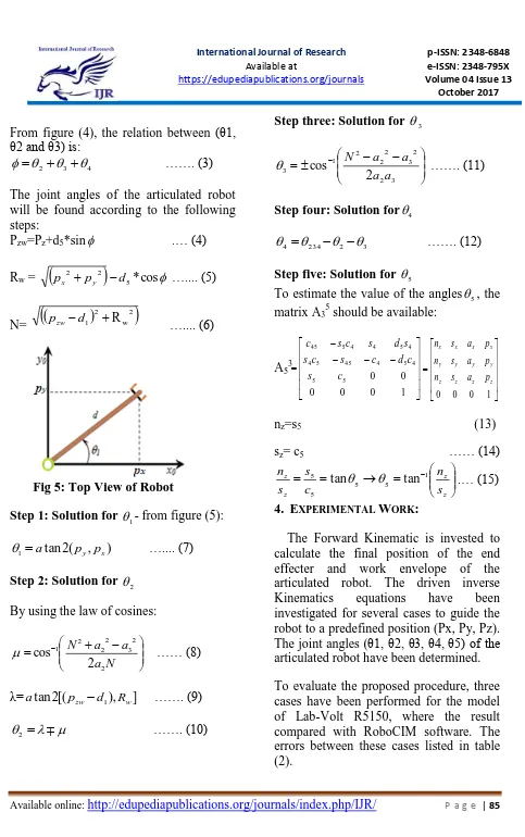
From figure (4), the relation between (θ1, θ2 and θ3) is:
4 3
2
……. (3)
The joint angles of the articulated robot will be found according to the following steps:
Pzw=Pz+d5*sin .… (4)
Rw =
5*cos2 2
d p
px y ….... (5)
N=
2 w 2
1 R
d
pzw ….... (6)
Fig 5: Top View of Robot
Step 1: Solution for 1- from figure (5):
) , ( 2 tan
1 a py px
….... (7)
Step 2: Solution for 2
By using the law of cosines:
N a a a N 2 2 3 2 2 2 1 2 cos
…… (8)
λ=atan2[(pzwd1),Rw] ……. (9)
2 ……. (10)
Step three: Solution for 3
3 2 2 3 2 2 2 1 3 2 cos a a a a N
……. (11)
Step four: Solution for4
3 2 234
4
……. (12)
Step five: Solution for 5
To estimate the value of the angles5, the matrix A35 should be available:
A53
nz=s5 (13)
sz= c5 …… (14)
z z z z s n c s s n 1 5 5 5 5 tan
tan .… (15)
4. EXPERIMENTAL WORK:
The Forward Kinematic is invested to calculate the final position of the end effecter and work envelope of the articulated robot. The driven inverse
Kinematics equations have been
investigated for several cases to guide the robot to a predefined position (Px, Py, Pz). The joint angles (θ1, θ2, θ3, θ4, θ5) of the articulated robot have been determined.
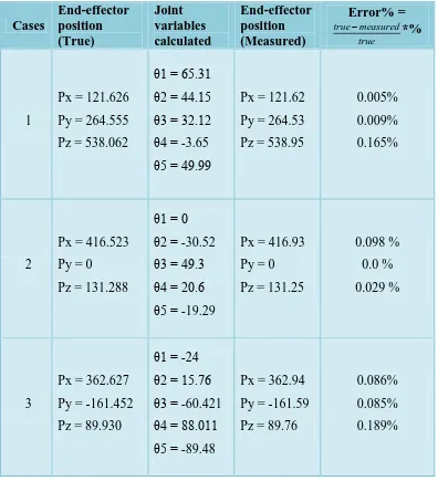
Table 2: Experiment and Simulation results for inverse kinematics of Lab-Volt R5150 robot arm
Error% =
true measured
true *%
End-effector position (Measured) Joint
variables calculated End-effector
position (True) Cases
0.005%
0.009%
0.165% Px = 121.62
Py = 264.53
Pz = 538.95 θ1 = 65.31
θ2 = 44.15 θ3 = 32.12 θ4 = -3.65 θ5 = 49.99 Px = 121.626
Py = 264.555
Pz = 538.062 1
0.098 %
0.0 %
0.029 % Px = 416.93
Py = 0
Pz = 131.25 θ1 = 0
θ2 = -30.52 θ3 = 49.3 θ4 = 20.6 θ5 = -19.29 Px = 416.523
Py = 0
Pz = 131.288 2
0.086%
0.085%
0.189% Px = 362.94
Py = -161.59
Pz = 89.76 θ1 = -24
θ2 = 15.76 θ3 = -60.421 θ4 = 88.011 θ5 = -89.48 Px = 362.627
Py = -161.452
Pz = 89.930 3
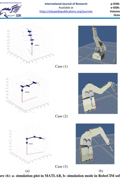
Case (1)
Case (2)
Case (3)
(a) (b)
5. Conclusion
Most industrial applications require access to a known goal, (i.e. the target is known coordinates (Px, Py, Pz), and driving the robot required derivation of inverse kinematic analysis for leading the robot to the specified target. The adopted method in this research and through many experiments proving its efficiency and compliance with the objective assigned to it through matching its dimensions perform tasks smoothly By adopting inverse kinematic analysis in this work we were able to identify the joints location for each movement of the robot's movements, allowing us to avoid obstacles during the path of the robot. There are two methods to solve inverse kinematic analysis are upper and lower solution and that used through the solution adopted in this research, according to the goal and the way to reach it. From the solution of the selected cases, we can observe that the value produce from upper solution is very close to the testing input than the results from lower solution and the percentage error between the true value and measured result are very close to each other.
References
[1] Laith A. Mohammed and Alaa Hassan Shabeeb, Inverse Kinematics Analysis Using Close Form Solution Method for 5 DOF Robots Manipulate, Engineering and Technology Journal, Vol.33, Part (A), No.9, 2015.
[2] John J. Craig, Introduction to Robotics, Mechanics and Control, 3rd edition, 2005.
[3] Mohammed Abu-Qassem, I.M.
and Simulation of 5 DOF Education robot Arm, IEEE, pp.569-574, 2010. [4] Mustafa Jabbar Hayawi, Analytical
Inverse kinematics Algorithm of A 5-DOF Robot Arm, Journal of education of college, no.4 volume1, 2011.
[5] Hazim Nasir Ghafil, Ali Hussein Mohammed and Nabil H. Hadi, A Virtual Reality Environment for 5-DOF Robot Manipulator based on XNA Framework, International Journal of Computer Applications (0975 – 8887) Volume 113 – No. 3, March 2015
[6] Tahseen Fadhel Abaas, Forward
Kinematics Modeling of 5DOF
Stationary Articulated Robots, Engineering and Technology Journal, Vol.31, No.3, 2013.