International Journal of Emerging Technology and Advanced Engineering
Website: www.ijetae.com (ISSN 2250-2459, UGC Approved List of Recommended Journal, Volume 7, Issue 11, November 2017)468
Nonlinear Vibration of Isotropic Thick Rectangular
Mindlin Plate with Different Boundary Condition
Ankit Dasgupta1, Atanu Dutta2
1,2M.Tech Students, School of Civil Engineering. KIIT University, Bhubaneswar, Odisha, India
Abstract: In recent years, there are many plate bending elements that emerged for solving both thin and thick plates. Plates on elastic foundation have wide application in structural engineering such as rough foundation, storage tanks, swimming pools etc. The main features of these elements are based on mixed formulation interpolation with discrete collocation constraints. The focus of the present study is only on free vibration of rectangular thick plate with an edge free and the formulation based on the Reissner-Mindlin plate theory, considering the first odder shear deformation effect taking into account of rotary inertia. The plate structure problems have been different combinations of boundary condition to determine the nonlinear natural frequency, mode shapes of plate. The static problem corresponding to a uniform transverse loading is solved first and the dynamic problem is subsequently taken up with the unknown deflection field. The Hamiltonian system based governing equation is first constructed. The eigenvalue problems of two fundamental vibrations are formed for a thick plate with an edge free and the others clamped. The present results for frequency parameter and the numerical model are in corporate after performing the test of convergence and experimental significance, validation has been done for large vibration around the fundamental resonance of the steel plate are tested and 3D mode shape are also plotted to show the deflected shape of the plates.
Key words: Isotropic thick plate, Shear deformation theory, finite element method, Mixed formulation, 3D mode shape, nonlinear frequency.
I. INTRODUCTION
In recent days, plate structures have established lot of interest by diversified and potential application in automobile and aerospace industry due to their strength capabilities. Plate structure play an important role in engineering application such as the bridge decks, storage tanks, foundation beds, aircraft panel etc. In solid mechanics, the plates are normally categories according to the ratio of thickness to the in-plane dimension and mechanical properties such as laminated composite plate, Mindlin-Reissner plate, functionally graded material plate (FGM) etc. Laminated composite plate is a combination of different type of composite and matrix materials and functionally graded material plate is made of a metal and ceramic [23,21]. In this paper we are considering isotropic thick rectangular Mindlin plate. During the last decade, a number of researchers applied dependability techniques to this isotropic thick plate. Ribeiro et al. [22] is trying to investigate the difference between oscillations of regular composite laminate plate and traditional laminate by using Newmark’s method. Talha et al. [16] using rectangular FGM plate and higher order shear deformation theory to find out the modification of transverse displacement in conjunction with finite element method (FEM). Among the large number of plate bending elements developed in recent years is a set of triangular and quadrilateral finite elements that were introduced by Zienkiewicz et al. [20] and Taylor
469
Senjanovic et al. [10] noted that the Mindlin theory operate with bending deflection as the basic variable for the total (bending + shear) deflection and the angle of rotation and also determined the formulation of eigenvalue problem and natural frequency. Wang et al. [3] the major difference between both plate theories are that the Ressiner plate theory was derived from the variation principle of the complimentary strain energy with linear bending stress distribution and on the other hand Mindlin formulated [4] the finite deference technique to calculate frequencies of rectangular plate with linear varying thickness. By making the formulation[9] of the problem and the fundamental solutions are satisfy with the boundary conditions of the original plate, the equation with respect to the natural frequency is obtained and the mode shape solutions corresponding to the natural frequencies has been formed. Comprehensive numerical results, including both the natural frequencies and associate mode shapes are listed to demonstrate the convergence and accuracy of the new analytic solution by satisfactory agreement with those formed the finite element analysis (FEA).
II. FUNDAMENTAL FREE VIBRATION PROBLEM
It is more difficult to obtain the exact solutions for the free vibrations of rectangular plate compared with thin plate, due to the increase of the number of governing equations and independent coordinates. For this reason many determinations were dedicated to develop approximate solutions with a maximum level of accuracy based on Mindlin plate theory (MPT). FEM, finite strip method, spline strip method, Rayleigh-Ritz method and collocation methods have been widely used to study the free vibrations of Mindlin rectangular plate. Liew et al.[18,26 ] have presented a wide-ranging literature survey on the research works up to 1994 on vibrations of thick plates. Shen et al [25] concluded that Dynamic response was determined by using both the modal superposition approach (MSA) and state variable approach (SVA). Many publications have appeared in the literature on the free of isotropic thick plates. At present study is associated with free vibration of isotropic thick rectangular Mindlin plate with various type of boundary condition by using finite element formulation and we have also discuss, a few existing work related to this computational procedure. The proposed theories exactly satisfy the transverse stress boundary condition on the bottom and top surface of the plate and the new results for the Eigen frequencies with different combination of classical boundary condition are incorporated after performing a convergence study and validation in special cases available in the literature. The effect of variations in the some material and geometric properties of the plate, we have been studied. Let us considered an isotropic thick rectangular plate of length (in x direction), breadth (in y direction) and uniform thickness as a, b and h respectively.
The fundamental study in the analysis of large amplitude vibration of rectangular plates is due to analytical study of free vibration [14, 24].
III. FUNDAMENTAL BOUNDARY CONDITION
In the contemporary investigation, non-linear free vibration analysis is done for isotropic thick plate and the coordination of the plates with its unreformed middle surface of the Cartesian co-ordinate system with its origin at “O” (x, y, z).[2] All the shear deformation theories are considered with the physical parameters like length to breadth ratio (b/a) (1, 2, 3, 4, 5) and thickness to length ratio (h/a) (0.1. 0.05, 0.01) respectively. The various boundary conditions have been considered. Four boundary conditions are considered and results are compared: (i) simply supported plate with immovable edges, (ii) all edges are clamped, (iii) two opposite edges clamped and simply supported and (iv) one edges are free and others edges are clamped. As shown in the figure, the thick rectangular plate with an edge free (denoted by “F”), simply supported (denoted by “S”) and clamped (denoted by “C”). now we considered “CCCC” , “SSSS”, “CSCS” and “CCCF” plates, where the four letters symbolic notation is used in anticlockwise direction.
IV. FORMULATION
A. Equilibrium equations
The equations of motion for free un-damped vibration of an elastic system undergoing large displacement can be expressed in the following matrix form,
K
M
0In which K and
M are overall stiffness and massmatrices and
is the displacement vector.B. Shape functions
If displacements at a node
r
of a quadratic isoparametric element areu v w
r r
,
,
r
,
xr
and
yr
,
then at any point inside the element In which,
ris the shape function at anode
r
u v w
x y
u v w
r r r r xr yr
C. Linear and Non-Linear Stiffness Matrices
The plate strains are describes in term of middle surface displacements i. e. x-y plane coincides with the middle surface.
470
Where
2 2 2 2 2 2 u x v y u v y x w x L w y w x y x y And
2 1 2 2 1 2 0 0 0 0 0 w x w y w w x y NL In which the first term is the linear expression and the second term gives non-linear terms. If linear elastic behavior is considered, the stress-strain relationship is written as
B B B
L NL
In which B L
, is the same matrix as in linear infinitesimal strain analysis, only B
NL
depends on the displacement. In general, B
NL
is found to be a linear function of such displacement. Therefore,
d d d B B d
L NL L NL
Which, because d
is arbitrary, gives the equilibrium equation as
0T
B D dv R
v
1
0 2
T
B B D B B dv R
L NL L NL
v
If N-notation is followed, the matrix K s
would be
obtained as
1 1
0 2 1 2 2
K K N N
s
The first term in the curly brackets of the above equation i.e. K0is independent of the displacements . N1is
linearly dependent upon
and2
is quadratically
dependent upon
. The matrix K s
is known as secant
stiffness matrix. The secant stiffness matrix obtained with B-notation is un-symmetric and that obtained with N-notation is symmetric. The correlation between the two notations is expressed as
0
T
K B D B dv
L L v
1 T T TN B D B B D B G S G dv
L NL NL L L
v
2 T TN B D B G S G dv
NL NL NL
v
The matrices S and SNLtogether give symmetric stress
matrix. The symmetric stress matrix is introduced as S SL SNL
And non-linear stiffness matrix
1 1
1 2
2 3
K N N
NL =
1 1 2 2T T T
B D B B D B B D B
NL L L NL NL NL
v
D. Mass Matrix
From the above relation, the mass matrix is obtained as
M
NT G T G
N dxdydzP P P
V
M NT m
N dxdy P
The mass matrix thus obtained above is known as consistent mass matrix.
V. ELEMENT STIFFNESS MATRIX
A. Linear element stiffness matrix
The element stiffness matrix for the plate is generated by the subroutine ELSM. The element stiffness matrix for the plate is generated and assembled in as a single array using skyline procedure. The material properties are read from main program. Subroutine ELSM generates BL needed
for evaluation of the element stiffness matrix. The linear
stiffness matrix of the element
KL is given by
11
T
L L L
K B D B J d d
471
B. Non-linear element stiffness matrix
The non-linear element stiffness matrix
KNL
for the planeis generated by subroutine ELSMN. The expression for the non-linear element stiffness matrix is
1 21 1
2 3
NL
K N N
Various matrices involved in the above equation are generated by the subroutine ELSMN. The integration of the products is performed by GAUSS subroutine which is based on Gauss quadrature. The non-linear stiffness matrix is renewed iteratively as the element stiffness is formed using the latest value displacement. Then the stiffness matrix is assembled and overall stiffness matrix formed.
VI. BENCH MARK,NATURAL FREQUENCY AND MODE SHAPE RESULT
Comprehensive bench mark analytic solutions of natural frequency and mode shape results are presented.Table 1-3, 4-6, 7-9 and 10-12 list of first 10 frequency parameter of solutions for the “CCCC”, “SSSS”. “CSCS” and “CCCF” plates with varying h/a ratio respectively. The Poisson’s
ratio (µ) is 0.3 and Young’s modulus (E) is 10920pa. The five different size ratio b/a are taken1-5.
Figure 1: A comparison of first ten frequency parameters of CCCC plate
with different mesh a G
[image:4.612.328.558.106.283.2] from FEM with analytical solution
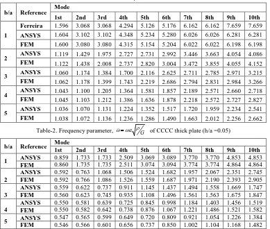
Table-1.Frequency parameter, a G of CCCC thick plate (h/a =0.1)
b/a Reference Mode
1st 2nd 3rd 4th 5th 6th 7th 8th 9th 10th
1
Ferreira 1.596 3.068 3.068 4.294 5.126 5.176 6.162 6.162 7.659 7.659
ANSYS 1.604 3.102 3.102 4.348 5.234 5.280 6.026 6.026 6.281 6.281
FEM 1.600 3.080 3.080 4.315 5.154 5.204 6.022 6.022 6.198 6.198
2 ANSYS 1.119 1.429 1.975 2.727 2.731 2.992 3.446 3.663 4.054 4.086
FEM 1.122 1.438 2.008 2.737 2.820 3.004 3.472 3.855 4.055 4.152
3 ANSYS 1.060 1.174 1.384 1.700 2.116 2.625 2.711 2.785 2.971 3.215
FEM 1.062 1.178 1.399 1.743 2.219 2.686 2.794 2.831 2.984 3.266
4 ANSYS 1.043 1.100 1.205 1.364 1.581 1.857 2.189 2.571 2.660 2.718
FEM 1.045 1.103 1.212 1.386 1.636 1.878 2.218 2.572 2.727 2.827
5 ANSYS 1.036 1.070 1.131 1.224 1.352 1.517 1.720 1.959 2.234 2.541
FEM 1.038 1.072 1.136 1.236 1.286 1.490 1.663 2.012 2.256 2.662
Table-2. Frequency parameter, a G of CCCC thick plate (h/a =0.05)
b/a Reference Mode
1st 2nd 3rd 4th 5th 6th 7th 8th 9th 10th
1 ANSYS 0.859 1.733 1.733 2.509 3.069 3.089 3.770 3.770 4.853 4.853
FEM 0.860 1.735 1.735 2.511 3.074 3.094 3.774 3.774 4.864 4.864
2
ANSYS 0.592 0.763 1.068 1.506 1.524 1.682 1.957 2.067 2.351 2.745
FEM 0.592 0.766 1.086 1.526 1.559 1.687 1.971 2.190 2.393 2.905
3
ANSYS 0.559 0.622 0.737 0.911 1.145 1.437 1.494 1.558 1.669 1.747
FEM 0.560 0.623 0.745 0.935 1.108 1.496 1.561 1.563 1.675 1.847
4
ANSYS 0.550 0.581 0.639 0.725 0.845 0.998 1.184 1.403 1.456 1.519
FEM 0.550 0.582 0.642 0.738 0.876 1.067 1.221 1.486 1.521 1.582
5 ANSYS 0.547 0.565 0.599 0.649 0.720 0.809 0.921 1.054 1.226 1.384
[image:4.612.114.503.353.683.2]472
Table-3. Frequency parameter, a G of CCCC thick plate (h/a =0.01)
b/a Reference Mode
1st 2nd 3rd 4th 5th 6th 7th 8th 9th 10th
1
Ferreira 0.175 0.364 0.364 0.536 0.667 0.667 0.827 0.827 1.088 1.088
ANSYS 0.178 0.363 0.363 0.536 0.664 0.665 0.827 0.827 1.088 1.088
FEM 0.177 0.364 0.364 0.536 0.664 0.667 0.827 0.827 1.088 1.088
2 ANSYS 0.121 0.156 0.220 0.313 0.318 0.352 0.412 0.434 0.499 0.584
FEM 0.121 0.157 0.224 0.318 0.324 0.353 0.415 0.461 0.508 0.624
3 ANSYS 0.114 0.127 0.151 0.187 0.236 0.297 0.311 0.325 0.349 0.372
FEM 0.114 0.127 0.152 0.192 0.249 0.312 0.325 0.326 0.351 0.388
4 ANSYS 0.112 0.119 0.130 0.148 0.173 0.205 0.244 0.290 0.309 0.317
FEM 0.112 0.119 0.131 0.151 0.180 0.220 0.273 0.309 0.317 0.330
5 ANSYS 0.133 0.140 0.149 0.164 0.184 0.191 0.218 0.277 0.353 0.355
FEM 0.111 0.115 0.123 0.134 0.151 0.174 0.206 0.248 0.303 0.309
Table-4. Frequency parameter, a Gof SSSS thick plate (h/a =0.1)
b/a Reference Mode
1st 2nd 3rd 4th 5th 6th 7th 8th 9th 10th
1
Ferreira 0.935 2.256 2.256 3.460 4.305 4.305 5.356 5.356 6.945 6.945
ANSYS 0.904 2.213 2.213 3.367 4.265 4.271 5.256 5.256 6.025 6.025
FEM 0.935 2.244 2.247 3.450 4.250 4.253 5.311 5.318 6.022 6.022
2 ANSYS 0.580 0.908 1.456 1.918 2.204 2.205 2.687 3.129 3.456 3.956
FEM 0.591 0.938 1.511 1.932 2.247 2.304 2.769 3.311 3.495 3.977
3 ANSYS 0.522 0.666 0.910 1.253 1.688 1.866 1.994 2.208 2.403 2.509
FEM 0.527 0.586 0.944 1.218 1.704 1.873 2.015 2.251 2.408 2.587
4 ANSYS 0.501 0.582 0.718 0.911 1.160 1.461 1.812 1.848 2.016 2.040
FEM 0.504 0.592 0.741 0.953 1.137 1.495 1.853 1.932 2.034 2.066
5 ANSYS 0.492 0.543 0.630 0.753 0.912 1.107 1.335 1.694 1.839 1.885
FEM 0.494 0.550 0.645 0.782 0.965 1.117 1.330 1.649 1.847 1.894
Table-5. Frequency parameter, a G of SSSS thick plate (h/a =0.05)
b/a Reference Mode
1st 2nd 3rd 4th 5th 6th 7th 8th 9th 10th
1 ANSYS 0.471 1.178 1.178 1.853 2.350 2.351 2.987 2.987 3.971 3.971
FEM 0.480 1.190 1.192 1.885 2.365 2.367 3.026 3.033 3.989 3.991
2
ANSYS 0.298 0.473 0.768 1.014 1.181 1.181 1.463 1.710 1.860 2.195
FEM 0.300 0.481 0.787 1.017 1.193 1.225 1.489 1.806 1.914 2.199
3
ANSYS 0.266 0.343 0.474 0.657 0.894 0.983 1.057 1.182 1.182 1.358
FEM 0.267 0.348 0.484 0.682 0.946 0.984 1.063 1.195 1.286 1.386
4
ANSYS 0.255 0.298 0.371 0.474 0.607 0.769 0.961 0.972 1.014 1.084
FEM 0.256 0.301 0.378 0.489 0.639 0.793 0.973 1.017 1.076 1.092
5 ANSYS 0.250 0.278 0.324 0.389 0.474 0.578 0.701 0.843 0.967 0.994
FEM 0.250 0.279 0.329 0.400 0.496 0.620 0.777 0.968 0.974 0.996
Table-6. Frequency parameter, a G of SSSS thick plate (h/a =0.01
b/a Reference Mode
1st 2nd 3rd 4th 5th 6th 7th 8th 9th 10th
1
Ferreira 0.097 0.243 0.243 0.389 0.493 0.493 0.638 0.638 0.855 0.855
ANSYS 0.097 0.245 0.245 0.392 0.503 0.503 0.649 0.648 0.888 0.888
FEM 0.097 0.243 0.244 0.390 0.493 0.494 0.638 0.641 0.856 0.856
2 ANSYS 0.060 0.097 0.157 0.207 0.243 0.243 0.303 0.355 0.389 0.457
FEM 0.060 0.097 0.160 0.207 0.244 0.251 0.306 0.373 0.396 0.457
3 ANSYS 0.054 0.070 0.097 0.134 0.183 0.200 0.216 0.243 0.243 0.281
FEM 0.054 0.070 0.098 0.138 0.193 0.200 0.217 0.244 0.263 0.284
4 ANSYS 0.051 0.060 0.075 0.097 0.124 0.157 0.197 0.198 0.207 0.222
FEM 0.051 0.061 0.076 0.099 0.129 0.169 0.198 0.207 0.220 0.223
5 ANSYS 0.050 0.056 0.066 0.079 0.097 0.118 0.143 0.172 0.100 0.203
473
Table-7.Frequency parameter, a G of CSCS thick plate (h/a =0.1)
b/a Reference Mode
1st 2nd 3rd 4th 5th 6th 7th 8th 9th 10th
1
Ferreira 1.295 2.398 2.930 3.841 4.350 5.138 5.512 5.899 6.951 7.298
ANSYS 1.301 2.413 2.946 3.882 4.373 5.167 5.582 5.975 6.025 6.026
FEM 1.311 2.423 2.941 3.904 4.338 5.104 5.579 5.951 6.022 6.022
2 ANSYS 0.642 1.078 1.729 1.944 2.295 2.554 2.858 3.497 3.605 3.970
FEM 0.651 1.107 1.786 1.955 2.329 2.671 2.927 3.538 3.753 3.988
3 ANSYS 0.540 0.727 1.021 1.701 1.874 1.885 2.022 2.267 2.439 2.604
FEM 0.544 0.742 1.056 1.482 1.880 2.023 2.040 2.306 2.485 2.686
4 ANSYS 0.509 0.609 0.771 0.992 1.267 1.593 1.851 1.932 1.965 2.066
FEM 0.511 0.619 0.795 1.039 1.357 1.657 1.856 1.943 1.993 2.142
5 ANSYS 0.495 0.557 0.659 0.799 0.976 1.188 1.432 1.709 1.841 1.891
FEM 0.497 0.564 0.675 0.832 1.038 1.299 1.622 1.748 1.900 1.992
Table-8. Frequency parameter, a G
of CSCS thick plate (h/a =0.05)
b/a Reference Mode
1st 2nd 3rd 4th 5th 6th 7th 8th 9th 10th
1 ANSYS 0.692 1.302 1.640 2.205 2.426 3.019 3.239 3.556 4.022 4.514
FEM 0.695 1.309 1.646 2.219 2.435 3.029 3.259 3.576 4.033 4.542
2
ANSYS 0.331 0.567 0.926 1.028 1.235 1.398 1.569 1.983 2.023 2.203
FEM 0.333 0.576 0.950 1.031 1.245 1.460 1.596 2.085 2.116 2.207
3
ANSYS 0.276 0.375 0.533 0.745 0.987 1.009 1.074 1.217 1.324 1.414
FEM 0.277 0.380 0.547 0.778 0.989 1.079 1.081 1.230 1.350 1.465
4
ANSYS 0.259 0.313 0.399 0.517 0.666 0.844 0.970 1.021 1.051 1.099
FEM 0.259 0.315 0.407 0.538 0.655 0.929 0.975 1.024 1.107 1.204
5 ANSYS 0.252 0.285 0.339 0.414 0.508 0.622 0.755 0.907 0.968 0.997
FEM 0.252 0.287 0.345 0.427 0.537 0.677 0.855 0.969 1.000 1.052
Table-9. Frequency parameter, a G
of CSCS thick plate (h/a =0.01)
b/a Reference Mode
1st 2nd 3rd 4th 5th 6th 7th 8th 9th 10th
1
Ferreira 0.142 0.271 0.349 0.472 0.519 0.671 0.708 0.795 0.899 1.023
ANSYS 0.140 0.271 0.349 0.473 0.520 0.672 0.710 0.796 0.900 1.026
FEM 0.142 0.270 0.344 0.468 0.510 0.652 0.698 0.777 0.868 1.001
2 ANSYS 0.067 0.116 0.190 0.210 0.254 0.290 0.326 0.415 0.426 0.459
FEM 0.067 0.117 0.194 0.210 0.255 0.302 0.330 0.436 0.444 0.459
3 ANSYS 0.055 0.076 0.109 0.152 0.201 0.207 0.220 0.250 0.273 0.293
FEM 0.056 0.077 0.111 0.158 0.201 0.220 0.221 0.252 0.298 0.303
4 ANSYS 0.052 0.063 0.081 0.105 0.136 0.173 0.198 0.212 0.216 0.225
FEM 0.052 0.063 0.082 0.109 0.144 0.190 0.198 0.209 0.226 0.247
5 ANSYS 0.051 0.057 0.069 0.084 0.103 0.127 0.154 0.186 0.197 0.203
FEM 0.051 0.058 0.069 0.086 0.109 0.137 0.174 0.197 0.204 0.214
Table-10. Frequency parameter, a G of CFFF thick plate (h/a =0.1)
b/a Reference Mode
1st 2nd 3rd 4th 5th 6th 7th 8th 9th 10th
1
Ferreira 1.093 1.757 2.735 3.261 3.356 3.860 4.642 4.977 5.373 5.465
ANSYS 1.092 1.758 2.692 3.259 3.354 3.853 4.648 4.955 5.364 5.453
FEM 1.088 1.751 2.700 3.232 3.326 3.850 4.605 4.866 5.360 5.367
2 ANSYS 1.035 1.176 1.505 2.052 2.645 2.796 2.809 3.104 3.264 3.582
FEM 1.036 1.179 1.512 2.081 2.654 2.804 2.890 3.114 3.271 3.603
3 ANSYS 1.062 1.086 1.215 1.433 1.654 2.167 2.639 2.676 2.838 2.900
FEM 1.029 1.088 1.219 1.446 1.790 2.262 2.648 2.714 2.845 2.869
4 ANSYS 1.028 1.057 1.125 1.236 1.400 1.619 1.896 2.418 2.610 2.637
FEM 1.027 1.059 1.127 1.243 1.420 1.670 2.005 2.434 2.646 2.683
5 ANSYS 1.024 1.045 1.086 1.153 1.250 1.380 1.547 1.751 1.990 2.662
474
Table-11. Frequency parameter, a G of CFFF thick plate (h/a =0.05)
b/a Reference Mode
1st 2nd 3rd 4th 5th 6th 7th 8th 9th 10th
1 ANSYS 0.575 0.949 1.505 1.809 1.889 2.692 2.294 3.146 3.251 3.848
FEM 0.575 0.948 1.506 1.808 1.888 2.688 2.879 3.147 3.252 3.850
2
ANSYS 0.546 0.630 0.807 1.112 1.476 1.545 1.566 1.751 2.105 2.152
FEM 0.546 0.625 0.809 1.127 1.477 1.568 1.593 1.755 2.053 2.215
3
ANSYS 0.542 0.574 0.645 0.765 0.941 1.173 1.465 1.472 1.512 1.591
FEM 0.542 0.574 0.647 0.772 0.963 1.229 1.474 1.513 1.580 1.593
4
ANSYS 0.541 0.558 0.595 0.657 0.741 0.867 1.022 1.205 1.423 1.471
FEM 0.541 0.558 0.596 0.661 0.758 0.896 1.084 1.329 1.473 1.495
5 ANSYS 0.540 0.551 0.574 0.611 0.664 0.735 0.827 0.968 1.169 1.458
FEM 0.540 0.551 0.575 0.613 0.671 0.753 0.865 1.014 1.207 1.455
Table-12. Frequency parameter, a G of CFFF thick plate (h/a =0.01)
b/a Reference Mode
1st 2nd 3rd 4th 5th 6th 7th 8th 9th 10th
1
Ferreira 0.118 0.197 0.319 0.383 0.403 0.584 0.639 0.725 0.882 0.905
ANSYS 0.118 0.197 0.320 0.383 0.404 0.585 0.639 0.692 0.725 0.883
FEM 0.117 0.196 0.314 0.379 0.398 0.577 0.619 0.675 0.705 0.863
2 ANSYS 0.111 0.128 0.165 0.229 0.308 0.321 0.327 0.368 0.431 0.441
FEM 0.111 0.128 0.166 0.233 0.308 0.327 0.331 0.368 0.434 0.466
3 ANSYS 0.110 0.117 0.132 0.157 0.193 0.242 0.303 0.307 0.315 0.332
FEM 0.110 0.117 0.132 0.158 0.198 0.254 0.307 0.316 0.328 0.333
4 ANSYS 0.110 0.114 0.121 0.134 0.153 0.178 0.210 0.249 0.294 0.307
FEM 0.110 0.114 0.122 0.135 0.155 0.184 0.224 0.275 0.307 0.312
5 ANSYS 0.110 0.112 0.118 0.117 0.140 0.154 0.177 0.209 0.235 0.376
FEM 0.110 0.112 0.117 0.125 0.137 0.154 0.178 0.209 0.250 0.303
VII. COMPARISON OF NUMERICAL AND EXPERIMENTAL RESULT
Here, we have considered five different lengths to breadth ratios b/a ranging from 1 to 5 and each ratio ten numerical frequency results are given for each type of plate. After calculated, the present solutions of Eigen frequencies are able to easily validate with the FEM results by using ANSYS software, where we have chosen rectangular thick plate, and considered the mesh size in equivalently (15x15). We note that we could actually use this boundary condition for clamped and simply supported
boundary conditions, the present results match pretty well of the other researchers. After we may sum up of all results, concluded that the Eigen frequencies are decreasing with increase in the thickness to length ratio (h/a) and are increasing with the increase in the b/a ratio in the face of the boundary condition assumed. Here presented the some deflected mode shape with reference to the Eigen frequencies for free vibration of thick isotropic rectangular plates with different boundary condition such as “CCCC”, “SSSS”, “CSCS”, “CCCF” are established respectively in fig(2-5).
475
FEMANSYS
[image:8.612.61.535.51.333.2]FEM
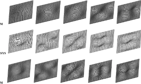
Figure 2: Comparison of FEM (top) and ANSYS (bottom) solution of first ten mode shapes of isotopic plate (b/a = 1 and h/a = 0.01) with boundary condition CCCC. The ten mode shapes are presented in two rows.
ANSYS
FEM
476
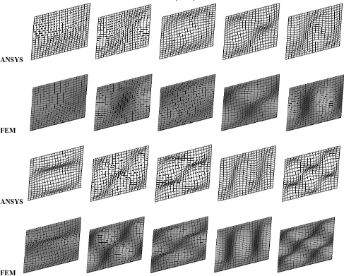
FEMFigure 3: Comparison of FEM (top) and ANSYS (bottom) solution of first ten mode shapes of isotopic plate (b/a = 1 and h/a = 0.01) with boundary condition SSSS. The ten mode shapes are presented in two rows.
ANSYS
FEM
ANSYS
FEM
Figure 4: Comparison of FEM (top) and ANSYS (bottom) solution of first ten mode shapes of isotopic plate (b/a = 1 and h/a = 0.01) with boundary condition CSCS. The ten mode shapes are presented in two rows.
[image:9.612.48.535.166.557.2]477
FEMANSYS
[image:10.612.48.535.51.307.2]FEM
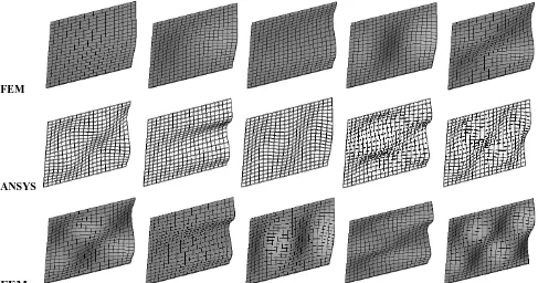
Figure 5: Comparison of FEM (top) and ANSYS (bottom) solution of first ten mode shapes of isotopic plate (b/a = 1 and h/a = 0.01) with boundary condition CFFF. The ten mode shapes are presented in two rows.
VIII. CONCLUSION
In this paper, Non-linear free vibration of isotropic thick rectangular plate is investigated with four proposed different boundary condition. The study is carried out following a novel method in which static analysis serves as the basis for the subsequent dynamic study. Calculations for different boundary condition of modal analysis are performed and results compared with the available literature to validate the present model. Comprehensive “FEM” and the software we are using “ANSYS” validated analytic natural frequency and mode shapes results are listed and very fast convergence regardless of the order of the mode. The solution convergence with the number of degree freedom, which is generalized co-ordinate in the expansion of the plate displacement. We also conclude that length-breadth ratio (b/a) and thickness to length ratio (h/a) are crucial factor that decide the nature of frequency and modes of free vibration of isotropic thick rectangular plate.
Reference
[1] Abdalla, J.A. and lbrahim, A.K. (2007). A geometrically nonlinear thick plate bending element based on mixed formulation and discrete collocation constraints. Structural Engineering and Mechanics, Vol. 26, No. 6, PP 1-15.
[2] Panda, S. and Barik, M. (2016). Finite element dynamic analysis of thin plates with complicated geometr. Proceedings of 24th ISERD International Conference, PP 41-44.
[3] Wang, C.M. Lim, G.T. Reddy, J.N. and Lee. K.H. (2001). Relationships between bending solutions of Reissner and Mindlin plate theories. Engineering Structures 23, PP 838–849.
[4] Lim, C.W. Lü, C.F. Xiang, Y. and Yao, W. (2009). On new symplectic elasticity approach for exact free vibration solutions
of rectangular Kirchhoff plates. International Journal of Engineering Science 47, PP 131–140.
[5] Hansbo, P. Heintz, D. and Larson, M.G. (2011). A finite element method with discontinuous rotations for the Mindlin– Reissner plate model. Comput. Methods Appl. Mech. Engrg. Vol 200, PP 638–648.
[6] Xing, Y. and Liu, B. (2009). Characteristic equations and closed-form solutions for free vibrations of rectangular mindlin plates. Acta Mechanica Solida Sinica, Vol. 22, No. 2, PP 125-136.
[7] Thai, H.T. and Choi, D.H. (2013). Analytical solutions of refinedplate theory for bending,buckling and vibration analyses of thick plates. Applied Mathematical Modelling. PP 1-13.
[8] Pradhan, K.K. and Chakraverty, S. (2015). Transverse vibration of isotropic thick rectangular plates based on new inverse trigonometric shear deformation theories. International Journal of Mechanical Sciences, vol 94-95, PP 211–231.
[9] Lezgy-Nazargah, M. (2016). A high-performance parametrized mixed finite element model for bending and vibration analyses of thick plates. Acta Mech DOI 10.1007/s00707-016-1676-4. © Springer-Verlag Wien 2016.
[10] Senjanovic´, I. Tomic´, M. Hadzˇic´, N. and Vladimir, N. (2017). Dynamic finite element formulations for moderately thick plate vibrations based on the modified Mindlin theory. Engineering Structures 136 . PP 100–113.
478
[12] Li, R. Wang, P. Xue, R. and Guo, X. (2017). New analyticsolutions for free vibration of rectangular thick plates with an edge free. International Journal of Mechanical Sciences 131– 132. PP 179–190.
[13] Saha, K.N. Misra, D. Ghosal, S. and Pohit, G. (2005). Nonlinear free vibration analysis of square plates with various boundary conditions. Journal of Sound and Vibration 287. PP 1031–1044.
[14] Amabili, M. (2004). Nonlinear vibrations of rectangular plates with different boundary conditions: theory and experiments. Computers and Structures 82. PP 2587–2605.
[15] Wu, J.J. (2003). Vibration of a rectangular plate undergoing forces moving along a circular path. Finite Elements in Analysis and Design 40. PP 41–60.
[16] Talha, M. and Singh, B.N. (2010). Static response and free vibration analysis of FGM plates using higher order shear deformation theory. Applied Mathematical Modelling 34. PP 3991–4011.
[17] Leung, A.Y.T. and Zhu, B. (2004). Geometric nonlinear vibration of clamped Mindlin plates by analytically integrated trapezoidal p-element. Thin-Walled Structures 42. PP 931–945.
[18] Xiang, Y. and Kitipornchai, S. (1995). Research on thick plate vibration: a literature survey. Journal of Sound and Vibration. Vol 180(1). PP 163-176.
[19] Oaate, E. Zienkiewicz, O.C. Suarez, B. and Taylor, R.L. (1992). A general methodology for deriving shear constrained reissner-mindlin plate elements. International journal for numerical methods in engineering, VOL. 33, PP 345-367.
[20] Zienkiewicz, O.C. Taylor, R.L. Papadopouls, P. and Onate, E. (1990). Plate bending elements with discrete constraints: new triangular elements. Compurrrs & Srructures Vol. 35. No. 4, pp. 505-522.
[21] Cen, S and Shang, Y (2015) Developments of Mindlin-Reissner Plate Elements. Hindawi Publishing Corporation,Mathematical Problems in Engineering,
[22] Ribeiro P and Akhavan H (2012) Non-linear vibrations of variable stiffness composite laminated plates, Composite Structures,PP-2424–2432.
[23] Guoyong J, Zhu S, Shuangxia S, Tiangui Y, Siyang G (2013) ” Three-dimensional exact solution for the free vibration of arbitrarily thick functionally graded rectangular plates with general boundary conditions”, Composite Structures, Accepted Manuscript.
[24] Abdalla J.A, Ibrahim A.M(2006) “Development of a discrete
Reissner–Mindlin element on Winkler foundation”, Finite Elements in Analysis and Design ,PP-740 – 748,
[25] Malekzadeh P, Karami G. (2004) “Vibration of non-uniform thick plates on elastic foundation by differential quadrature method”, Engineering Structures PP-1473–1482
[26] liew k. m., xiang ,y. and kitipornchai$ s.(1993) “transverse vibration of thick rectangular plates-i. comprehensive sets of
boundary conditions”, Computers& Structures Vol. 49, No. I, pp. l-29.
[27] Mishra a.k (2008) “ finite element large amplitude free flexural vibration analysis of isotropic plates”, Department of civil engineering National institute of technology Rourkela-769008, thesis.